myGekko B Series User manual

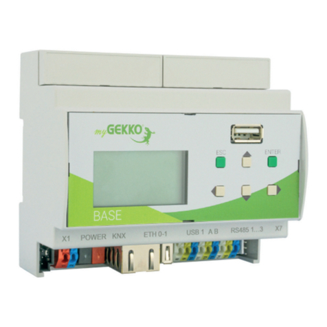
myGEKKO BASE R22
Technical manual
myGEKKO BASE R22
Technical manual

2
Table of contents
1 Safety and warranty.........................................................................3
2 General information......................................................................... 5
3 Technical specifications..................................................................6
3.1 Digital Inputs...................................................................................7
3.2 Analogue Inputs............................................................................. 8
3.3 Digital outputs................................................................................ 9
3.4 Analogue outputs...........................................................................9
3.5 AUX1/RS-485................................................................................10
3.6 Ethernet connection.....................................................................10
3.7 WLAN Network.............................................................................12
4 REG Installation instructions.........................................................14
4.1 User group.................................................................................... 14
4.2 General safety information..........................................................14
4.3 Installation instructions............................................................... 14
5 External fuse protection................................................................ 16
6 Commissioning controller............................................................. 17
6.1 Text display.................................................................................. 17
6.2 Web access.................................................................................. 18
7 Configuration.................................................................................. 19
8 List of connections........................................................................ 21
9 Notes...............................................................................................23

3
1 Safety and warranty
These reliable devices are built according to the current rules of technology.
They were tested and left the factory in perfect condition.
However, there are residual risks. Read and follow the safety instructions to
avoid hazards.
Ekon GmbH assumes no liability for damages caused by non-observance of
safety instructions.
Used safety
instructions
The following notes indicate special hazards when handling devices or provide
useful hints:
Hints in these boxes are general tips on text that will be highlighted.
NOTE
The signal word Note indicates useful tips and recommendations for the
efficient handling of the product.
CAUTION
Health damage/Property damage
The respective warning symbol in conjunction with the signal word Caution
indicates a danger that can lead to slight (reversible) injury or material dam-
age.
WARNING
Serious damage to health
The respective warning symbol in conjunction with the signal word Warning
indicates an imminent danger, that can lead to death or serious (irreversible)
injuries.
DANGER
Danger to life/Serious damage to health
The respective warning symbol in conjunction with the signal word Danger
identifies an imminent danger that leads to death or serious (irreversible)
injuries.
Safety information Safety instructions for the product described in this document are listed below.
Please note these when using the product.

4
DANGER
Electrical Voltage!
Danger to life and fire due to electrical voltage
Inside the device are unprotected live components. Observe the VDE regu-
lations. Disconnect all cables to be installed and take precautions against
unintentional switching on. Do not operate the device if damaged. Decom-
mission the device or system and secure it against unintentional operation
if it can be assumed that safe operation is no longer guaranteed.
CAUTION
Device damage due to external influences!
Moisture and contamination of the equipment can destroy the equipment.
Protect devices from moisture, dirt and damage during transport, storage
and operation.
Warranty The device is intended solely for proper use. Any improper modification or non-
observance of the operating instructions invalidates any warranty or guarantee
claim. After unpacking, the device must be inspected immediately for mechan-
ical damage. If there is damage in transit, the supplier must be informed im-
mediately. The device may only be operated as a fixed installation, ie only when
installed and after completion of all installation and commissioning work, and
exclusively in the environment provided for this purpose. Ekon GmbH shall not
be liable for changes to standards after publication of the operating instruc-
tions.

5
2 General information
myGEKKO B.Series BASE R22 is a REG controller for the implementation of all
areas of modern building control.
The combination of numerous complex control algorithms with a user-friend-
ly and easy-to-understand interface enables the visualisation and operation
of various building functions via smart devices such as smartphones, tablets,
laptops or PCs. The configuration and commissioning is carried out directly
via myGEKKO B.Series BASE R22 and via the already installed software. Com-
missioning takes place via the IO configuration or the parameterisation level.
Programming skills are not necessary for this.
Features n4x digital inputs 24VDC (DI)
n4x analogue inputs (AI)
n2x digital outputs 24VDC (DO)
n4x digital outputs 230VAC (DO)
n2x Analogue outputs (AO)
n2x RS485
n1x microUSB
n2x Ethernet ports
n1x WLAN modem
n1x microSD card slot

6
3 Technical specifications
Parameters Value
Housing Plastic
Color White similar to RAL9003
Installation REG installation
Dimensions 98.7 x 105 x 64mm
Weight 280 g
Operating temperature +5°C to +40°C
Storage temperature -20°C to +70°C
Ambient humidity Max. 85% RH not condensing
Supply voltage 24 VDC
Power consumption (internal) Max. 200mA
Protection class IP20
Degree of soiling 2
Protection class III
Certifications: Directive 2014/53 / EU (RED)
Directive 2014/30 / EU (EMCD)
Directive 2014/35 / EU (LVD)
Directive 2011/65 / EU (ROHS)
Health and Safety of the User:
EN 60950-1:2006
+A1+A2+A11+A12+CORR1
EN 60730-1:2016
Electromagnetic compatibility:
EN 61000-6-2:2005+CORR
EN 61000-6-3:2007+A1
Restriction of Hazardous Sub-
stances:
EN 50581:2012
EN60947-4-1
EN60721-3-3

7
Connection data Parameters Value Note
Insulation stripping
length
7 mm
DI 0.1 -1.5 mm² Plug-in screw terminal
AI 0.1 -1.5 mm² Plug-in screw terminal
DO (RO) 0.1 -2.5 mm² Plug-in screw terminal
DO (SSR) 0.1 - 2.5 mm² Plug-in screw terminal
AO 0.1 -1.5 mm² Plug-in screw terminal
Care 0.1 - 2.5 mm² Plug-in screw terminal
3.1 Digital Inputs
The inputs are galvanically isolated from the module via optocouplers.
Parameters Value
Input Optically isolated/optocoupler
Circuit insulation voltage 1 kV
Input voltage 18-30V DC / 18-26VAC
Switching point <5V DC / AC max.
Input 1
Input 2
COM (Input 1-4)
Input 3
Input 4

8
3.2 Analogue Inputs
Parameters Value/Resolution
PT 1000 input -50 to 150°C
Resolution: 0.01°C
Deviation: 0.25%
Voltage input Voltage: 0-10V
Deviation: 0.25%
Power input Electricity: 0-25mA
Deviation 1%
Input AI1, AI2 fixed:
1. PT1000 -50 ... 150°C
Input AI3, AI4 switchable via DIP switch:
nPT1000 -50 ... 150°C
AI3: J1=OFF, J2=ON
AI4: J3=OFF, J4=ON
nVoltage 0V – 10 V
AI3: J1=ON, J2=OFF
AI4: J3=ON, J4=OFF
nCurrent 0 – 20 mA
AI3: J1=OFF, J2 OFF
AI4: J3=OFF, J4=OFF
In addition, an external resistor 125 ohms is required.

9
3.3 Digital outputs
Parameters Value
RO output (digital relay output) Single-pole switch with working con-
tact Continuous load current: 5A
Switching voltage: 250VAC / 30VDC
Isolation
(EN 60947-4-1 ed. 3 general use,
AC1, no inductive loads)
(EN60730-1: 2017: Chapter 13, Ta-
ble 12)
DO output: (Solid State Relays
(SSR))
Continuous load current: 0.4 A
Switching voltage: 24V AC / DC
Isolation 1kV
EN 60947-4-1 ed. 3 general use,
AC1, no inductive loads
Digital relay output 1
Digital relay output 3
Digital relay output 2
Digital relay output 4
SSRO
SSRO
COM for DO5 and DO6
3.4 Analogue outputs
Parameters Value
Output 0-10V
Max. 10 mA
Isolation voltage 1 kV

10
Parameters Value
Typical load 10kOhm
Analogue output 1
Analogue output 2
GND analogue output
3.5 AUX1/RS-485
Parameters Value
Interface RS-485
Baud rates 9.600, 19.200, 38.400, 57.600 and
115.200
Parity adjustable
TS (Termination Switch) 180 ohm terminal resistance
3.6 Ethernet connection
Parameters Value
Ethernet type 10/100 base T
Circuit insulation voltage 1kV electrically isolated
The two Ethernet ports are separated by default, thus a technology network
(ETH1) and an Internet network (ETH0) can be realised. Ports can also be

11
bridged via software to create a unified network. There are several ways to do
this:
Bridged (default) In this network mode, the two Ethernet ports are bridged, i.e. there is only one
network. This mode is suitable for connecting e.g. two controllers B.Series
BASE R22
CAUTION
Devices with a high data throughput rate must not be "bridged" via
myGEKKO B.Series BASE R22.
This leads to high CPU load and possible damage to the device.

12
Switch In this network mode, both Ethernet ports are disconnected, i.e. two networks
are created. Example multi-family house, with common technology (heating,
ventilation).
3.7 WLAN Network
Parameters Value
Standards IEEE 802.11 a/b/g/n Dual Band
Bandwidth 20 MHz
The integrated WLAN module can be operated as a client (subscriber) or as
an access point (access point).
WLAN access
point mode:
The WLAN access point mode is only intended for commissioning and pro-
vides a non-encrypted network. For more information, see chapter 4.2 Web
access.
WLAN client
mode:
In client mode, myGEKKO B.Series BASE R22 can connect to a WLAN network
with encryption type WPA2. To configure this mode with SSID and password,
you must connect to myGEKKO via the web interface, log in as a Configura-
tor and access the network settings. For more information on accessing your
myGEKKO, see chapter 4.2 Web access.
In the client mode, the WLAN network is the main network and the LAN net-
work is automatically set to Bridged mode. Thus, only the additional IP address

13
can be set in the LAN network, whereby myGEKKO B.Series Base 22 can also
address devices in the LAN network or can be controlled over the same.

14
4 REG Installation instructions
4.1 User group
The installation and assembly of electrical equipment may only be performed
by a qualified electrician. Failure to follow the instructions may result in dam-
age to the unit, fire, or other hazards.
NOTE
These instructions are part of the product and must remain with the end
customer.
In principle, the valid electrical installation regulations for domestic installa-
tions must be observed and adhered to.
4.2 General safety information
Inside the housing there are voltage carrying elements. Touching terminals is
life threatening if the system is not disconnected from the mains. There are
no serviceable parts inside the device. The opening of the housing is therefore
only permitted by employees of the manufacturer.
CAUTION
Beware of external voltage on the product!
When servicing the product or the connected peripherals, all connections to
the mains must always be disconnected. Take into account all circuit break-
ers which supply dangerous voltages to the device. Mains voltage must not
be applied to the terminals as long as the ground connection point is not
properly grounded.
4.3 Installation instructions
The units are designed for stationary operation and must be mounted in such
a way that contact with voltage carrying terminals is excluded during normal
operation.
NOTE
As a rule, the product is mounted under covers. During installation, partic-
ular care must be taken to ensure that the equipment is protected against
environmental influences for example, water, moisture and dirt.
The devices may only be connected when the power supply is de-energized.
Depending on the installation, either snapping onto DIN rails (C-35) or screw
fixing (surface mounting) can be selected by a mounting plate.

15
The strain relief of the connecting cables must be made during the installation.
The modules have no strain relief.

16
5 External fuse protection
The 24VDC supply voltage must be externally fused according to the cross-
section of the connection wires and the maximum current consumption of the
device.
WARNING
For the B.Series BASE R22, it must be ensured that the maximum current of
the digital outputs is limited by an external fuse:
nDO 1-4: 5 A @ 230 V
nDO 5-6: 0,4 A @ 24 V
All connection wire cross-sections must be designed according to the maxi-
mum permissible current.

17
6 Commissioning controller
6.1 Text display
The text display is used to read current information about the network status
and to change various settings. The menu is structured as follows:
Navigation The navigation of the controller is done exclusively via the arrow keys.
To change a setting, first press the confirmation button. Now the setting is
changed with the arrow keys and confirmed with the confirmation key.
Info LAN
nETH0 IP: IP Address Main Network (Bridge / Switch)
nETH0 MASK: Subnet mask main network (Bridge / Switch)
nETH0 GW: Gateway of the main network (Bridge / Switch)
nETH0 IP2: IP address of the subnetwork (bridge / switch / WLAN)
nETH1 IP: IP address of the second network interface (only available in
switch mode)
nETH1 MASK: Subnet Mask Main Network 2 (Bridge / Switch)
WLAN
nWLAN IP: IP address WLAN network
nWLAN MASK: Subnet mask WLAN network
nWLAN GW: Gateway of the WLAN network
DNS
nAddress of the DNS server
Settings To access the settings, please enter the password "1000".
Network mode
nLAN-STATIC: Switch mode with static IP address
nLAN-DHCP: Switch mode with DHCP
nLAN-STATIC-BRIDGED: Bridge mode with static IP address
nLAN-DHCP-BRIDGED: Bridge mode with DHCP
nWLAN-DHCP: WLAN client mode with DHCP
Apply Network Changes
nAfter changing the network settings, tap the right button to activate the
settings immediately. Otherwise, they will only take effect after a restart.
WLAN-AP
nUse this function to activate the WLAN access point during commission-
ing. For more information, see chapter 4.2 Web access.

18
Service Factory reset
nThis function is used to reset the network and security settings including
access passwords. The I/O settings, however, remain untouched. This
feature reboots the system
Reboot
nThis function is used to restart the system.
Viewer
nThis function is used to activate the viewer.
6.2 Web access
myGEKKO B.Series BASE R22 can be accessed via the web browser in two
different ways:
Access over the
LAN network (eth0
or eth1)
myGEKKO B.Series BASE R22 has a fixed IP address in the delivery state; the
network is bridged and access to myGEKKO user interface can be made via a
browser of the latest generation via the address http://192.168.2.252:8080.
Access via a
service access
point
Activate the WLAN AP via the text display of myGEKKO B.Series BASE R22.
Connect your WLAN e.g. on the smartphone with "myGEKKO_BNIO".
Then open your web browser and connect to the address
http://192.168.149.1:8080
This WLAN AP is unencrypted and is only used to set up your myGEKKO.
Please disable this wireless AP again after setup. The WLAN AP is automati-
cally deactivated after a restart.
NOTE
Parallel access to myGEKKO B.Series BASE R22 across multiple browsers
and devices is not possible; only direct access is allowed.
Factory settings When resetting to factory settings, the I/O configuration will not be changed.
nNetzwork: LAN DHCP
nUsername: admin
nPassword: mygekko
nLocal web access http / HTTPS: Enabled
nVNC: Locked
nmyGEKKO Viewer: Locked
nmyGEKKO Net: Locked
LAN Static If the network type is set to LAN Static, the following IP addresses are adopted
by default.
nDefault IP Address: 192.168.2.252

19
7 Configuration
Default passwords nUser: w
nAdministrator: ww
nConfigurator: mygekko
Access
configuration
There are the following options for accessing myGEKKO B.Series BASE R22:
nEnable the B.NIO WLAN access point (only recommended for first ac-
cess)
nLAN network with input via browser from http://192.168.2.252:8080
nmyGEKKO Viewer (the first access after activating the viewer may take
about 2 minutes)
nLive Viewer via myGEKKO Plus services
NOTE
As the Viewer or the Live Viewer are much faster than accessing directly via
the Access Point, it is recommended to activate the Viewer via the WLAN
Access Point of the B.Series BASE R22 or to activate the Plus Services for
the Live Viewer
Network Network settings must be applied by tapping on "Apply settings", as otherwise,
you will not have access to the B.Series BASE R22 directly after changing the
network settings.
IO configuration In the IO configuration, you will find all inputs and outputs that are directly on
myGEKKO B.Series BASE R22, under the menu item "ONBOARD".

20
AI assignment AI 1 and AI 2 are only designed for PT1000 sensors. In the case of the IO con-
figuration, however, AI 1 and AI 2 can still be selected for AI Voltage and AI
Current, these are without function.
NOTE
If an AI sensor type has been defined and subsequently changed, a restart
is required for the values to be displayed correctly. Example: Change in AI3
of PT1000 to 0 - 10 V voltage
This manual suits for next models
1
Table of contents
Other myGekko Controllers manuals
Popular Controllers manuals by other brands

Adaptec
Adaptec 2120S - SCSI RAID Controller Installation and user guide

Emerson
Emerson PACSystems RX3i manual

Martin Audio
Martin Audio AQX - SCHEMATICS manual

Linak
Linak HOMELINE TWINDRIVE TD2 user manual

Senninger
Senninger SENNODE-BT quick start guide

Eaton
Eaton Crouse-Hinds Flex-Station EDS Series Installation & maintenance information