Sicherheit
VORSICHT! Elektrische Spannung!
Im Innern des Geräts benden sich ungeschützte spannungsführende Bau-
teile. Die VDE-Bestimmungen beachten. Alle zu montierenden Leitungen
spannungslos schalten und Sicherheitsvorkehrungen gegen unbeabsich-
tigtes Einschalten treffen. Das Gerät bei Beschädigung nicht in Betrieb
nehmen Das Gerät bzw. die Anlage außer Betrieb nehmen und gegen unbe-
absichtigten Betrieb sichern, wenn anzunehmen ist, dass ein gefahrloser
Betrieb nicht mehr gewährleistet ist. Das Gerät ist ausschließlich für den
sachgemäßen Gebrauch bestimmt. Bei jeder unsachgemäßen Änderung
oder Nichtbeachten der Bedienungsanleitung erlischt jeglicher Gewähr-
leistungs- oder Garantieanspruch. Nach dem Auspacken ist das Gerät
unverzüglich auf mechanische Beschädigungen zu untersuchen. Wenn
ein Transportschaden vorliegt, ist unverzüglich der Lieferant davon in
Kenntnis zu setzen. Das Gerät darf nur als ortsfeste Installation betrieben
werden, das heißt nur in montiertem Zustand und nach Abschluss aller
Installations- und Inbetriebnahmearbeiten und nur im dafür vorgesehenen
Umfeld. Für Änderungen der Normen und Standards nach Erscheinen der
Bedienungsanleitung ist Ekon GmbH nicht haftbar.
Technische Daten
Parameter Wert
Farbe Schwarz
Montage u.P. Schalterdose
Abmessungen B x H x T / 71 x 71 x 20 mm
Betriebstemperatur -5 °C bis 45 °C
Ausgangsssignal 4 x potentialfrei max. Leitunglänge 5 m
Anschluss 6-polig Tasterausgänge BUT
Schutzart IP20
Zertifzierungen
DIN EN 50491-1:2014, DIN EN 60669-
1:2009, DIN EN 55011:2011, DIN EN
61000-4-2:2009, DIN EN 61000-4-3:2011,
DIN EN 61000-4-4:2013, DIN EN 61000-4-
5:2015, DIN EN 61000-4-6:2014
Sicurezza
ATTENZIONE! Tensione elettrica!
All’interno dell’apparecchio sono presenti componenti sotto tensione non
protetti. Attenersi alle speciche della norma VDE. Scollegare i cavi da
montare dall’alimentazione elettrica e adottare tutte le misure necessarie
per impedire un reinserimento accidentale.Non mettere in funzione l’appa-
recchio danneggiato. Spegnere l’apparecchio e/o l’impianto e assicurarlo
contro il reinserimento accidentale se si sospetta che non possa più esse-
re garantito un funzionamento sicuro. L’apparecchio deve essere utilizzato
esclusivamente in modo conferme alle normative. In caso die modiche
improprie o mancata osservanza delle istruzioni per l’uso, decade qualsi-
asi forma di garanzia. Dopo il disimballaggio, l’apparecchio deve essere
immediatamente controllato per vericare la presenza di eventuali danni
meccanici. In caso di danni da trasporto, informare tempestivamente il for-
nitore. L’apparecchio deve essere utilizzato unicamente come installazione
ssa, ovvero dopo essere stato montato, al termine di tutti gli interventi di
installazione e di messa in funzione necessari e solo nel contesto previsto.
Ekon srl declina ogni responsabilità per eventuali modiche delle norme e
degli standard intervenute dopo la pubblicazione delle istruzioni per l’uso.
Parametri Valore
Colore Nero
Montaggio scatola interruttore uP
Dimensioni L x A x P / 71 x 71 x 20 mm
Temperatura di esercizio Da -5 ° C a 45 ° C
Segnale di uscita 4x a potenziale zero, lunghezza cavo
max. 5 m
Connessione a 6 vie Uscite pulsante BUT
Tipo di protezione IP20
Certicazioni
DIN EN 50491-1:2014, DIN EN 60669-
1:2009, DIN EN 55011:2011, DIN EN
61000-4-2:2009, DIN EN 61000-4-
3:2011, DIN EN 61000-4-4:2013, DIN
EN 61000-4-5:2015, DIN EN 61000-
4-6:2014
Security
CAUTION! Electric voltage!
The device contains unprotected live components. Observe the VDE
regulations. Disconnect the cables to be installed from the power sup-
ply and take safety precautions against accidental switch-on. In case
of damage do not start the device. Unplug the device or the plant from
the power supply and take precautions against accidental switch-on as
soon as you assume that operation of the unit under safe circum-
stances is no longer possible. The device is exclusively intended for
appropriate use. Any improper use or non-observance of the operating
instructions invalidates the right to claim under guarantee or warranty.
After removing the packaging, check the condition of the unit to assure
there is no mechanical damage. Inform the supplier immediately in
case of transport damage. The unit is designed for xed installations;
this means that it can be used only mounted and after nishing all
further installation and commissioning works, and only in the foreseen
environment. Ekon is not liable for modications of the applied norms
and standards after the publication of the operating instructions.
Parameters Value
Color Black
Assembly u.P. switch box
Dimensions W x H x D / 71 x 71 x 20 mm
Operating temperature -5 °C to +45 °C
Output signal 4 x potential-free max. Cable length
5 m
6-pin connection Button outputs BUT
Protection type IP20
Certications
DIN EN 50491-1:2014, DIN EN 60669-
1:2009, DIN EN 55011:2011, DIN EN
61000-4-2:2009, DIN EN 61000-4-
3:2011, DIN EN 61000-4-4:2013, DIN
EN 61000-4-5:2015, DIN EN 61000-
4-6:2014
myGEKKO | Ekon GmbH
St. Lorenznerstraße 2
I-39031 Bruneck
T. +39 0474 551 820
myGEKKO | EKON Vertriebs GmbH
Fürstenrieder Straße 279a
D-81377 München
T. +49 8921 5470711
www.my-gekko.com
A First Class Product of Europe
A company from South Tyrol
GEK.EBU.TAS.0401
RAUMBUS
Zusatztaster 4fach
Pulsante aggiuntivo 4 vie
Additional push-button 4-fold
Version 17.11.22 - MRK.PRB.TAS.0401
eingetragen im Handelsregister in Bozen mit
Steuer- und Eintragungsnummer IT01637750215
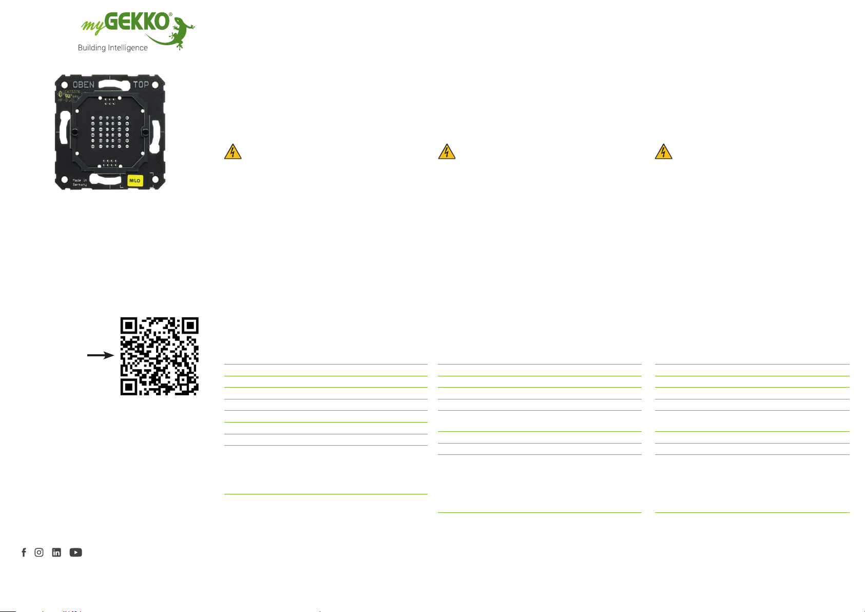
Ein Tastsensor für die einfache Erweiterung des Busank-
opplers um 4 weitere Sensoren. Er wird in Kombination mit
dem Busankoppler GEK.BUS.RBB.BA01 verwendet.
IT
Descrizione del prodotto
EN
Product description
Sensore a pulsante per una facile espansione dell‘accop-
piatore bus con 4 sensori aggiuntivi. Viene utilizzato in
combinazione con l‘accoppiatore bus GEK.BUS.RBB.BA01.
A button sensor for easy expansion of the bus coupler by
4 additional sensors. It is used in combination with the
GEK.BUS.RBB.BA01 bus coupler.
Zum Produkt
Al prodotto
To the product
wiki.my-gekko.com
Technical data
Dati tecnici
DE
Produktbeschreibung


