MYiR MYC-YT507H Guide

MYIR-MYC-YT507H-HW-HDG-EN_V1.0
- 1 -
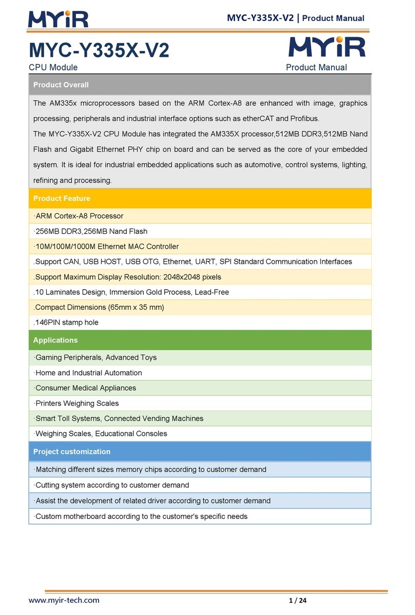
MYC-YT507H
Hardware Design Guide
File status:
[ ]The draft
[ √ ] Official release
File ID:
MYIR-MYC-YT507H-HW-HDG-EN
Version:
V1.0
Author:
Dana
Date created:
2022-04-15
Date updated:
2022-04-15
Copyright © MYIR Electronics Limited 2020-2030 all rights reserved.

MYIR-MYC-YT507H-HW-HDG-EN_V1.0
- 2 -
History
Version
Author
Participants
Date
Description
V1.0
Dana
20220415
Initial Version

MYIR-MYC-YT507H-HW-HDG-EN_V1.0
- 3 -
Contents
History.................................................................................................................................... - 2 -
Contents.................................................................................................................................- 3 -
1. Overview.............................................................................................................- 6 -
1.1. Supported products....................................................................................................- 6 -
1.2. Disclaimer......................................................................................................................- 6 -
2. Power supply design.........................................................................................- 7 -
2.1. Reference Design....................................................................................................... - 7 -
2.2. Power Protection........................................................................................................- 7 -
2.3. Power Sequence ......................................................................................................... - 8 -
2.4. Layout Guidelines.......................................................................................................- 9 -
3. Boot configure ..................................................................................................- 10 -
3.1. Reference Design.....................................................................................................- 10 -
4. Reset and key circuit design ........................................................................ - 11 -
4.1. Reference Design.....................................................................................................- 12 -
4.2. Layout Guidelines.................................................................................................... - 12 -
5. Interface circuit design ...................................................................................- 13 -
5.1. SMHC........................................................................................................................... - 13 -
5.1.1. Reference design ..........................................................................................- 14 -
5.1.2. Layout guidelines.........................................................................................- 15 -
5.2. UART.............................................................................................................................- 16 -
5.2.1. UART to RS232............................................................................................ - 16 -
5.2.2. UART to RS485............................................................................................ - 17 -
5.2.3. UART to USB................................................................................................ - 18 -
5.2.4. Layout Guidelines.......................................................................................- 19 -
5.3. USB................................................................................................................................- 20 -
5.3.1. Reference Design....................................................................................... - 20 -
5.3.2. Layout Guidelines.......................................................................................- 20 -
5.4. Ethernet.......................................................................................................................- 22 -

MYIR-MYC-YT507H-HW-HDG-EN_V1.0
- 4 -
5.4.1. Reference Design....................................................................................... - 22 -
5.4.2. Layout Guidelines.......................................................................................- 23 -
5.5. MIPI CSI ....................................................................................................................... - 24 -
5.5.1. Reference Design....................................................................................... - 24 -
5.5.2. Layout Guidelines.......................................................................................- 24 -
5.6. Parallel CSI..................................................................................................................- 25 -
5.6.1. Reference Design....................................................................................... - 26 -
5.6.2. Layout guidelines.........................................................................................- 26 -
5.7. I2C................................................................................................................................. - 27 -
5.7.1. Reference design ..........................................................................................- 27 -
5.7.2. Layout guidelines.........................................................................................- 27 -
5.8. LVDS............................................................................................................................. - 28 -
5.8.1. Reference design ..........................................................................................- 28 -
5.8.2. Layout guidelines.........................................................................................- 29 -
5.9. HDMI............................................................................................................................ - 30 -
5.9.1. Reference Design....................................................................................... - 30 -
5.9.2. Layout Guidelines.......................................................................................- 30 -
5.10. TV OUT ......................................................................................................................- 31 -
5.10.1. Reference Design.....................................................................................- 31 -
5.10.2. Layout Guidelines.................................................................................... - 31 -
5.11. SPDIF-OUT...............................................................................................................- 32 -
5.11.1. Reference Design.....................................................................................- 32 -
5.11.2. Layout Guidelines.................................................................................... - 32 -
5.12. AUDIO I2S................................................................................................................ - 33 -
5.12.1. Reference Design.....................................................................................- 33 -
5.12.2. Layout Guidelines.................................................................................... - 33 -
5.13. Line OUT...................................................................................................................- 34 -
5.13.1. Reference Design.....................................................................................- 34 -
5.13.2. Layout Guidelines.................................................................................... - 34 -
5.14. ADC.............................................................................................................................- 35 -
5.14.1. Reference Design.....................................................................................- 35 -
5.14.2. Layout Guidelines.................................................................................... - 35 -
6. Design checklist.............................................................................................. - 36 -

MYIR-MYC-YT507H-HW-HDG-EN_V1.0
- 5 -
6.1. Power supply design................................................................................................ - 36 -
6.2. system start up Check............................................................................................- 36 -
6.3. Peripheral circuits design ........................................................................................- 37 -
Appendix A..........................................................................................................- 38 -
Warranty & Technical Support Services..................................................................- 38 -

MYIR-MYC-YT507H-HW-HDG-EN_V1.0
- 6 -
1. Overview
This document is intended to assist hardware engineers in designing board-level circuits based on
the MYC-YT507H core module. Please be fully aware of the document before you begin your
design.The document contains common information such as design references, layout suggestions,
and design checklists to assist hardware engineers.
Resources referenced in this document is from the MYIR Electronics website, included in the
MYC-YT507H product information download page, you can download them in the following
website: http://d.myirtech.com/MYD-YT507H/
In addition, MYIR Electronics the following resources to speed up your design:
Core board / evaluation board product manual;
Evaluation board principle graphical source file;
Related device manuals.
1.1. Supported products
This document is suitable for all models of MYC-YT507H series core boards.
1.2. Disclaimer
Some of reference designs in the document are based on MYIR electronic evaluation boards
and cannot be guaranteed to be suitable for all application scenarios. If your product has
special requirements for application scenarios or technical specifications, please adjust the
design according to the actual situation.
Reference design and layout in the document are recommended for reference only and do not
necessarily contain all the matters needing attention. Please make adjustments according to
the actual situation.
MYIR shall not be liable for any form of technical endorsement or joint liability for any
proposal contained in any document.

MYIR-MYC-YT507H-HW-HDG-EN_V1.0
- 7 -
2. Power supply design
The design of the power supply system is of vital importance in the design of embedded products,
engineers need to consider not only the basic electrical parameters of power itself, but also the
stability of the power supply design, such as electromagnetic compatibility, temperature range,
safety design, etc. Any neglect of these factors may lead to the entire system cannot work
normally. Before starting to design a power supply system for a new product, the engineer should
thoroughly understand the actual needs of the whole system, and comprehensively demonstrate a
feasible design scheme based on cost and efficiency, so as to select an appropriate power supply
method for the system.
2.1. Reference Design
The core board needs to provide 5V voltage for normal operation, and the average current is about
2A under full load condition. In order to ensure the stable and reliable operation of the system, it
is recommended to use 3A power chip to supply power to the core board separately. It is not
recommended to use this power chip to drive loads outside the core board, especially some high-
power load devices.
The power supply chip can be LDO or DCDC. LDO has the advantages of simple use, low cost,
small electromagnetic interference, but high calorific value. DCDC has the advantages of strong
current output capacity, high conversion efficiency and low calorific value, but high
electromagnetic interference. If the input voltage is close to 5V, use the LDO power chip. If the
input voltage is different from 5V, use the DCDC power chip.
Core board 5V power supply, please increase the energy storage capacitor and decoupling
capacitor appropriately near the core board 5V voltage input pin.
Figure 2-1 Core board 5V power supply
2.2. Power Protection
In order to ensure the reliability of the power supply system, it is not recommended to directly
supply the external unopened input voltage directly to the input of the power supply chip, and the
power supply can be processed after processing the power supply to improve the reliability of the
input power supply. Safety and reduce electromagnetic interference. The bottom board input

MYIR-MYC-YT507H-HW-HDG-EN_V1.0
- 8 -
power supply in the design is 12V, only as an example, the value of the input power should be
determined according to your actual needs.
Figure 2-2 General power input circuit
Figure 2-3 Power input circuit in noise-sensitive situations
2.3. Power Sequence
The MYC-YT507H core board and carrier board have power-on sequence requirements. Ensure
that the core board is powered on first. It is recommended to enable power supply for 5V and
3.3V peripherals of the carrier board after initialization of the core board. Figure 2-4 shows the
reference circuit.
The core board is reset at low level. When the reset signal rises, it indicates that the voltage inside
the core board has been output stably, that is, the minimum system of the core board has been
initialized when the reset signal rises (1.8V). When the reset signal rises, the MOS tube Q13 is
turned on. Q13 turns on, Q14 turns on, and finally VDD_5V turns on.
Figure 2-4 carrier board peripherals Power-on timing circuit

MYIR-MYC-YT507H-HW-HDG-EN_V1.0
- 9 -
2.4. Layout Guidelines
The distance between different power supply planes should be at least 20mil;
Widen the width of the power line and ground wire as far as possible, to meet the required
rated current value, the width of the feedback signal should not be too narrow, it is
recommended to be more than 10mil;
If DCDC is used, the signal line is not recommended in the area below the inductance;
If DCDC is used, the current loop path should be as short as possible, and the inductor and
capacitor should be placed as close to the chip as possible, i.e. the red and green paths in the
figure below
Figure 2-5 DCDC current backflow path
If LDO is used, it is necessary to pay attention to the thermal resistance of the LDO chip,
because the thermal resistance of the LDO chip is relatively high. It is recommended to add
the grounding pad and make more ground vias on the grounding pad.
Choose the capacitance of small ESR as far as possible
The power chip with digital ground and analog ground shall be separated from each other and
only connected at a single point at the input of the main power supply. The analog ground
shall not be connected to the grounding pad.

MYIR-MYC-YT507H-HW-HDG-EN_V1.0
- 10 -
3. Boot configure
After a power-on reset, the T507-H processor starts up by executing the program in the chip's
internal BROM. BROM starts by reading the voltage level of the pin of BOOT SEL[4:0], and the
levels of different combinations will enter the specific starting source.
BOOT SEL[4:0] pins do not add pull-up or pull-down design in the core board. But there is a 15K
pull-up resistor inside the chip by default. MYC-YT507H core board start up mode mainly has
eMMC start up, Micro SD card start up. See Table 3-1.
BOOT SEL[4:0]
Initial Boot Source
Description
11011
Micro SD-> eMMC
Boot from microSD card first, eMMC second
10111
Micro SD
Can only boot from Micro SD card
Table 3-1 Boot configure
3.1. Reference Design
Figure 3-1 Boot configure reference design

MYIR-MYC-YT507H-HW-HDG-EN_V1.0
- 11 -
4. Reset and key circuit design
MYC-YT507H core board provides 3 special pins, the function is Reset, ONOFF start off, FEL
burning mirror. During design, it is suggested to reserve resistance and capacitor to form a simple
RC filter to filter out the jitter interference when the key is pressed, while avoiding the
interference introduced from the key to affect the reset signal.In the harsh electromagnetic
environment, in order to eliminate the electrostatic interference from the key to ensure more
reliable operation of the system, another ESD device can be connected in parallel. If there are
more stringent requirements for chattering elimination, logic circuits such as RS flip-flops can be
considered to build reset circuits.
Pin
Description
CPU-RESET
(PIN 9)
POR power failure reset pin. RC reset circuit or hardware watchdog reset chip can be use
d to reset the output.
CPU-ONOFF
(PIN 10)
Usually there is an external button. If you press the button for the first time, the system
shuts down automatically. If you press the button again, the system starts up. When the
system is in hibernation, press this key to wake up the system.
FEL
(PIN L16)
The FEL signal is pulled up inside the CPU. After power-on, BROM detects the FEL level s
tatus. If a low level is detected, the T507-H enters download mode, and the system imag
e can be downloaded through the USB port.
Figure 4-1 Reset and ONOFF pin function description

MYIR-MYC-YT507H-HW-HDG-EN_V1.0
- 12 -
4.1. Reference Design
Figure 4-2 reset Reference design
Figure 4-3 external hardware watchdog Resetting reference circuit
4.2. Layout Guidelines
The width of reset signal line should not be too narrow, it is recommended not less than 8mil;
Reset signal is sensitive signal, which is recommended to be surrounded by ground;
Place TVS as close to the button as possible.

MYIR-MYC-YT507H-HW-HDG-EN_V1.0
- 13 -
5. Interface circuit design
5.1. SMHC
SMHC stands for SD/MMC Host Controller. MYC-YT507H core board support leads to two
SMHC interfaces. It is recommended to use the SMHC0 interface for Micro SD circuits and the
SMHC1 to use peripherals with SDIO WIFI or other SDIO interfaces.
When designing the SD/SDIO/MMC card interface circuit, you only need to connect these
interfaces to the SD/MMC card accordingly.Take the SMHC0 circuit as an example, see Figure 5-
2.
Figure 5-1 SD/SDIO/MMC interface

MYIR-MYC-YT507H-HW-HDG-EN_V1.0
- 14 -
5.1.1. Reference design
Figure 5-2 SD card Reference design
Figure 5-3 WIFI reference circuit

MYIR-MYC-YT507H-HW-HDG-EN_V1.0
- 15 -
5.1.2. Layout guidelines
Single-ended signal 50 Ωimpedance;
Trace match the data line and control line to be within 100 mils;
SD1_CLK is recommended to be surrounded with ground. If not, ensure the distance between
the clock signal and other signals follow 3W rule.
Avoid placing other irrelevant devices and wiring in the U5 packaging area (including the
BOTTOM layer);
Y1 and Y2 clock signals are processed in the whole process, far away from other clocks and
signals;
Antenna signal WL_ANT, ANT and WIFI module are routed on the same layer to avoid layer
change, and A GND back flow hole is added on both sides of the antenna routing, the
distance between the GND holes is 50 Ω, and the impedance is controlled. If 4 layers are
designed, usually hollow out the second layer and use the third layer reference. The purpose
of this is to increase the distance between the signal line and the reference plane so that the
PCB line width of the signal line can be wider without affecting the 50Ωimpedance control.
The antenna seat element should be placed far away from the power supply and high
frequency signal, and the distance from the antenna signal to the seat element should be as
short as possible.

MYIR-MYC-YT507H-HW-HDG-EN_V1.0
- 16 -
5.2. UART
The MYC-YT507H core board supports up to six serial ports. Due to the pin reuse of the chip, the
core board only uses 4 channels of serial port by default, among which UART1 has flow control
(RTS and CTS signal) function, and the other 3 channels of UART only have TXD and RXD by
default.
In the reference design, UART signal can be used as follows: UART to RS232, UART to RS485,
AND UART to USB.
When the UART is directly connected to the debugging serial port, the UART signal itself is TTL
3.3V level, so the UART to USB converter cable is needed to facilitate the connection with the
PC. Figure 5-4 shows the common USB to UART TTL module.
Figure 5-4 USB to UART TTL module
5.2.1. UART to RS232
In the reference circuit, The UART to RS232 chip is SP3232EY-L conversion chip of EXAR
Company, and the signal isolation chip is ADUM1201BRZ chip of ADI Company. The converted
RS232_TX/RX can be directly connected to the RS232 connector.
The 5V_ISO is produced by a special isolation power supply chip, and the B0505S-1WR2
isolation power supply of Jin Sheng yang is used in the reference circuit. Note That the power
module has a minimum load value and a 10K resistance (R389) is required as the default load.

MYIR-MYC-YT507H-HW-HDG-EN_V1.0
- 17 -
Figure 5-5 Isolate RS232 reference circuit
Figure 5-6 Isolating 5V power reference circuit
5.2.2. UART to RS485
Reference circuit UART to RS485 chip is TI ISO3802DW isolation conversion chip, the chip
integrated signal isolation function, do not need to add additional signal isolation chip. The
converted RS485_A/B can be directly connected to the RS485 connector.
The 5V_ISO is produced by a special isolation power supply chip, and the B0505S-1WR2
isolation power supply of Jin Shengyang is used in the reference circuit. Note that the power
module has a minimum load value and a resistance of 10K (R389) is required as the default load.

MYIR-MYC-YT507H-HW-HDG-EN_V1.0
- 18 -
Figure 5-7 isolation rs485 reference circuit
Figure 5-8 Isolating 5V power reference circuit
5.2.3. UART to USB
The reference circuit uses FT234xD-T conversion chip to convert UART debugging serial port
signal to USB signal. USB interface adopts Type C USB connector, which is easy to plug and
unplug.

MYIR-MYC-YT507H-HW-HDG-EN_V1.0
- 19 -
Figure 5-9 Debug serial port reference circuit
5.2.4. Layout Guidelines
Keep sufficient spacing between signal and power plane before and after isolation;
The 120 Ωresistor (R5) in the RS485 circuit is placed close to the conversion chip;
TVS tube is placed close to connector;
RS485 signal differential impedance 100 Ω, isometric control error ±300mil.
USB signal differential impedance 90 Ω, isometric control error +-10mil.

MYIR-MYC-YT507H-HW-HDG-EN_V1.0
- 20 -
5.3. USB
T507-H chip integrates USB2.0 Host controller and USB2.0 OTG controller. The Host controller
can provide three USB2.0 Host interfaces, and the OTG controller provides one USB2.0 interface.
MYC-YT507H core board brings it all out.
If users want to use THE OTG function of USB, they can use Micro USB port or Type C USB
port.
It is recommended that a fuse be added between the power supply of the USB module and
VDD_5V for protection. The reference circuit uses a 4-wire USB port. If a 5-wire USB port is
used, the ID signal of the port needs to be connected to GND.
TVS tube and common-mode inductance are recommended for USB signal.
5.3.1. Reference Design
Figure 5-10 USB Type C Interface reference circuit
Figure 5-11 USB HOST Interface reference circuit
5.3.2. Layout Guidelines
USB signal line does the equal length control, error range ±10mil;
Other manuals for MYC-YT507H
1
Table of contents
Other MYiR Computer Hardware manuals
Popular Computer Hardware manuals by other brands

Tronsmart
Tronsmart TF12 manual

Atheros
Atheros AR5BCB-00012 PC Card quick start guide

Avaya
Avaya 1100 Series Expansion Module user guide

Arbor Technology
Arbor Technology EmCORE-i89M2 Quick installation guide

Dini Group
Dini Group DNBFC_S12_PCIe Hardware manual

Klark Teknik
Klark Teknik HELIX DN9848 Operator's manual