MYPV ELWA User manual

ELWA®Modbus Interface Operation Manual, 171018
ELWA®Modbus Interface
Operation Manual
1. Assembly
Before placing into operation it is essential to read the assembly instructions provided with the
device and the ELWA manual.
2. System requirements
The ELWA Modbus Interface can be used with all ELWA devices with firmware Version 1.30 or
higher. Devices with serial numbers lower than 120100160810xxxx are equipped with earlier
firmware versions.
To update the ELWA firmware a USB Interface is required. The update is not possible by
using the ELWA Modbus Interface.
If the ELWA Modbus Interface is used in combination with the Smart-Home System
LOXONE, the "Loxone RS485 Interface" and not the "Loxone Modbus Interface" has to be used,
otherwise Bus conflicts may occur.
The latest software packages are available at www.my-pv.com.
3. Operation displays
The 3 LEDs on the top are the operation displays on ELWA. Functions are described in the ELWA
instruction manual.
The 3 green LEDs underneath show the operation condition of the ELWA Modbus Interface:
No LED light: no power supply
all 3 LED blinking: no connection to the ELWA
upper LED light: connection to the ELWA ok
middle LED light: Modbus order received (timeout approx. 5 sec)
LED operation display
Green (on ELWA)
Yellow (on ELWA)
Red (on ELWA)
green
green
green

ELWA®Modbus Interface Operation Manual, 171018
A proper communication between ELWA und ELWA Modbus Interface is only possible with
exact positioning (see assembly instructions).
4. Pins
Power supply Either with the provided power supply unit via Micro USB interface
(5VDC) or with 12-24V DC at the two pins +24V/GND
Temperature sensor Connect the provided temperature sensor at the two „Temp“ pins.
Polarity does not matter.
Modbus Connect the Modbus at the pins A D+ and B D-.
Consider polarity!
5. Functionality
The ELWA Modbus Interface is a link between the ELWA and a Modbus based bus system.
Because of the bus capability the allocation of bus addresses is required when there are
multiple devices in operation (register 1030).
The bus address is saved in the interface, not in the ELWA.
Furthermore the interface can control the hot water securing of ELWA by the provided
temperature sensor. For this purpose the following settings have to be made:
The hot water securing (Boost) even is operative without an active Modbus.
Assuming that the additional temperature sensor in the boiler is positioned higher than the
ELWA, it is recommended to set the boost-temperature on the interface (register 1009) a little
higher (e.g. 70 °C). Thereby the ELWA-internal control for hot water securing can be
circumvented.
The ELWA-internal control of the boost-time needs also to be adjusted. The corresponding entry
(register 1020) has to be set to 1441.

ELWA®Modbus Interface Operation Manual, 171018
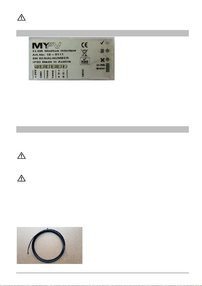
If the sensor (see figure) indicates a value >80 °C the pins may not be connected correctly or
there might be a sensor break. A negative value can be an indication of a short circuit.
Terminating resistor in the bus system
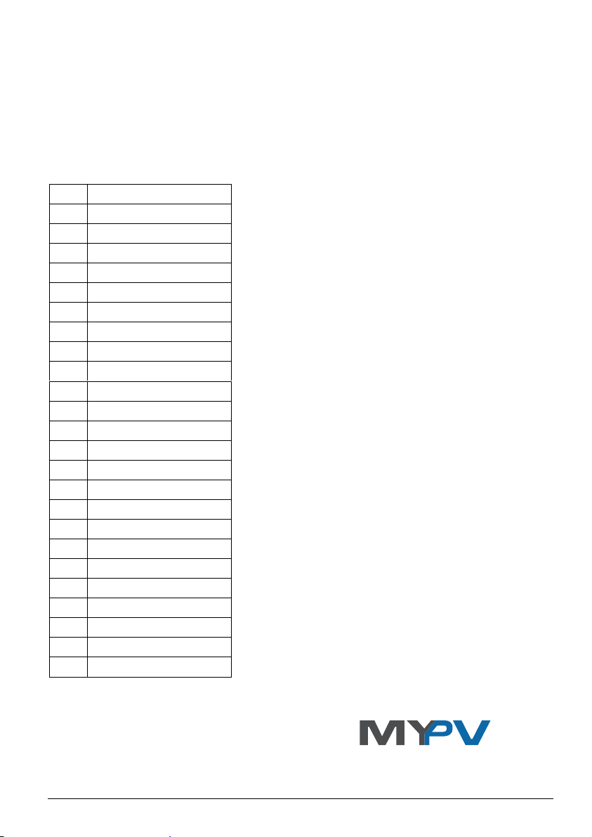
Bus systems are high-resistive. For this reason, a terminating resistor (120 Ohm) must be set,
ideally at the most remote location of the bus master. The resistance is included in the package.
6. Modbus register description
Modbus RTU Standard, Comm parameters 9600/8/N/1, All registers unsigned int (16 bit)
Register Address mode Content
1000 R Operating Day Counter
1001 R/W Operation mode (see Table 1), write 1 skips 10 minutes startup delay
1002 R DC Breaker status, 0: open, 1: closed
1003 R DC Relay status, 0:open, 1: closed
1004 R/W AC Relay status, 0: open, 1: closed, write to register starts/stops ELWA AC relay
1005 R Temperature in 1/10°C
1006 R Current Water Temp Day minimum in 1/10°C
1007 R Current Water Temp Day maximum in 1/10°C
1008 R DC Temp Setting in 1/10°C
1009 R/W AC Temp Setting In 1 / 10°C
1010 R Internal Temperature of Electronics in °C
1011 R DC Isolation value
1012 R DC Voltage 0.1V
1013 R DC Current mA
1014 R DC Power in W
1015 R Current Day DC Energy in Wh
1016 R Total DC Energy kwh
1017 R Current Day AC Energy in Wh
1018 R Internal clock (minutes from noon)
1019 R Minutes since current day wakeup
1020 R/W AC boost mode, AC switch on time in minutes from noon
0 ELWA internal temperature controlled
1-1440 ELWA internal time controlled in minutes from noon
>1440 ELWA internal control off, controlled via ELWA Modbus Interface

ELWA®Modbus Interface Operation Manual, 171018
1021 R ELWA Modbus Interface temperature sensor in 1/10°C
1022 R/W ELWA Modbus Interface boost temperature control setting in 1/10°C
0 inactive (factory preset),
1-700 start boost at setting –40 (4°C hysteresis), stop boost at setting
set register 1020 to >1440 if 1022 is >0.
1023 R/W Temp sensor offset calibration in 1/10°C, do not adjust unless sensor is changed
1030 W address of device (01 factory preset)
Table 1: Operation mode
0
startup
1
switchdivert
2
switch_off
3
switch_on
4
setupmode
5
wait_for_dc
6
charge_elko
7
rel_dc_on
8
check_upvswon_dcsupply
9
wait
10
check_position
11
mpp_scan
12
mpp_track
13
start_lower_unit
14
stop_lower_unit
15
wait_for_start_sequence
16
wait_for_stop_sequence
20
upv_lowerthan_upvswoff
21
temp_derating
129
error_overtemp_fuse
130
error_overtemp_measured
131
error_overtemp_chip
134
error_hardware_fault
135
error_iso_fault
136
error_temp_sensor
Subject to change.
my-PV GmbH
Teichstrasse 43, 4523 Neuzeug
www.my-pv.com
Table of contents