1. Adjust the directions of the sensor and the axial orientation, neaten the wire after sensor installation
2. Wire of control box: red — “ACC”, black — “ground”, white — “reversing signal”, yellow — “speed
signal”. Well connected the wire between control box and display, keep the sensor disconnect.
3. Start the car, inside temperature showing in the display
4. Start the car in reversing gear, the reversing light turning on. Insert a sensor to the control box, if
there is no obstacle in front and the display showing”.”, that means that the system is working
normally. People should be detected normally if standing within 1m ahead. Pull out the sensor and test
other sensors the same way. After testing, connect 4 sensors to corresponding ports of the control box.
5. Start the car in reversing gear, set us an obstacle behind to make the system on alarming status.
Press the switch on the display to adjust the volume or turn off to mute. Pay attention to the following
during the installation and adjustment of sensors:
a. If the system beeps as “Bi...” after one sensor connected, please check whether there is any
obstacles around it, or the sensor is fixed too tight or close to great interference source(such as vent-
pipe, wires);
b. If the system beeps as “Bi... Bi...” and there is no obstacles around it, the sensor may detect the
ground or some outshoots of the car(such as registration mark etc.), please check the directions of the
sensor and axes;
c. If the sensor couldn’t work properly after the above mentioned handling, the sensor can be regarded
defective, or unmatch with the control box. The system should be replaced.
d. Please pay attention to the mark of the sensor like A.B.C.D while connecting to control box. The
mark on the sensor should be corresponding to the mark on the control box.
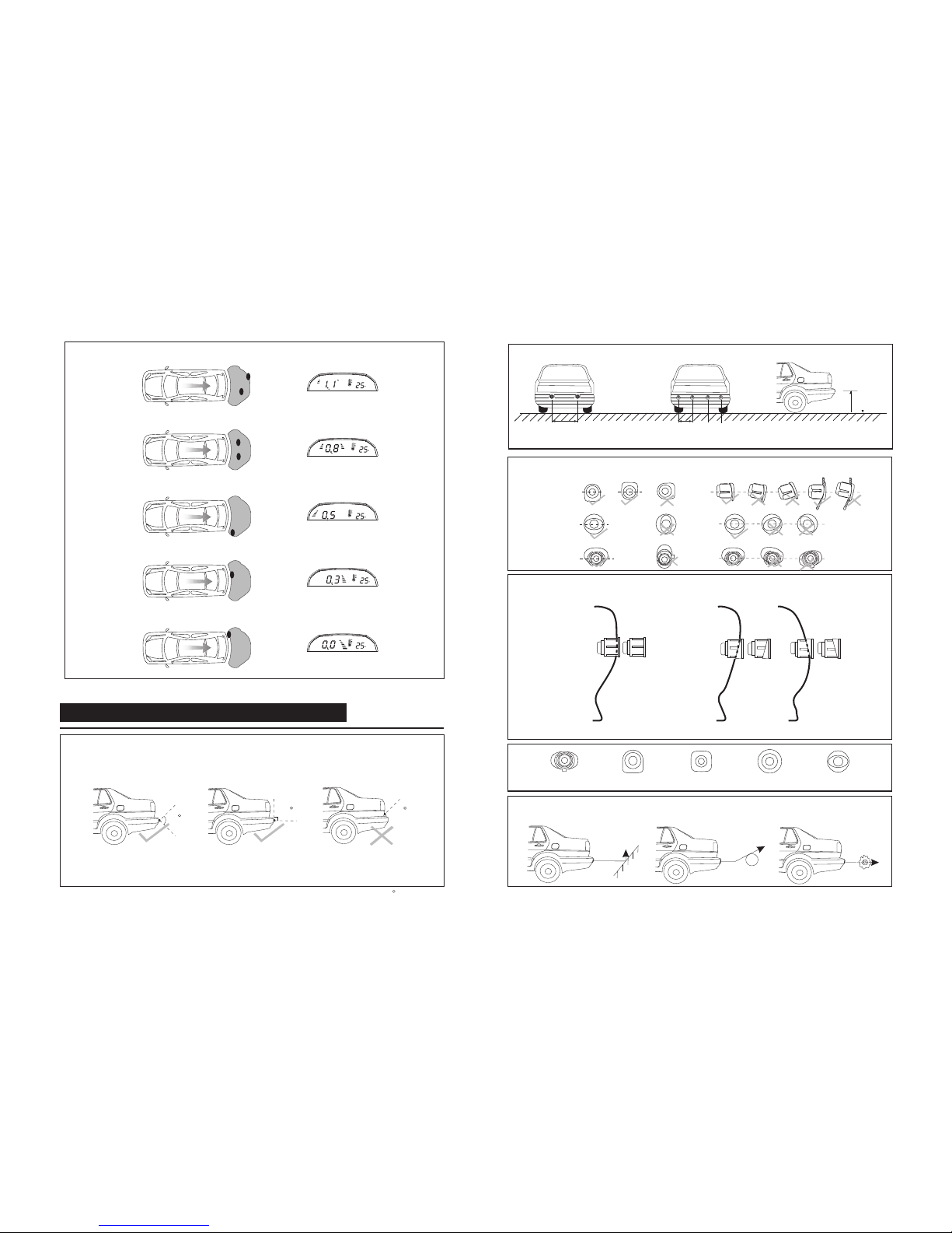
e. If the distance from the obstacle to the car is <0.3m, it will show “0.0” in the display (but not 0.2/0.1m)
to warn the driver to stop the car.
The max. speed limitation setting up of the system:
If the real speed is exceeding the set max. speed, the system wouldn’t alarm to any obstacles
no matter the system is on reversing status; If the real speed is under the set max. speed and
the system is on reversing status, it will alarm if there is obstacle.
The operation of setting up the max. speed is as below:
Connect all the wires according to the “WIRING DIAGRAM”, start the car in reversing gear and
proceed with a speed. Then press the button inside the small hole on the display, the system will
record the speed and regard it is the max. speed.
The function is optional, if it is not needed, the yellow signal wire of the control box can be
disconnected to the speed signal of the car, and the working system is not concerned with the
speed.
4.Switch D6 used to choose if the distance in the distance in the display has minimized 0.2m to
Switch D5
OFF
ON
Switch D6
OFF
ON
ALARM MODE
When switch D6 is at the position "ON", the corresponding data for alarm mode and distance
0.0-0.4
0.5
0.6-0.8
0.9-1.1
1.2-1.4
1.5-1.6
1.7
1.8-∞
Digital display(m)
0.0
0.3
0.4-0.6
0.7-0.9
1.0-1.2
1.3-1.4
1.5
dot
Awareness
Danger area
Alarm area
Safe area
Bars
3green+2yellow+2red
none
Alarm sound
Bi...
Bi.Bi.
Bi..Bi..
Bi...Bi...
Bi....Bi....
none
Bi....Bi....
Stage
1
2
3
4
5
6
7
8
0.0-0.2
0.3
0.4-0.6
0.7-0.9
1.0-1.2
1.3-1.4
1.5
1.6-∞
0.0
0.3
0.4-0.6
0.7-0.9
1.0-1.2
1.3-1.4
1.5
dot
1
2
3
4
5
6
7
8
INSTALLATION AND TEST
INSTALLATION STEPS
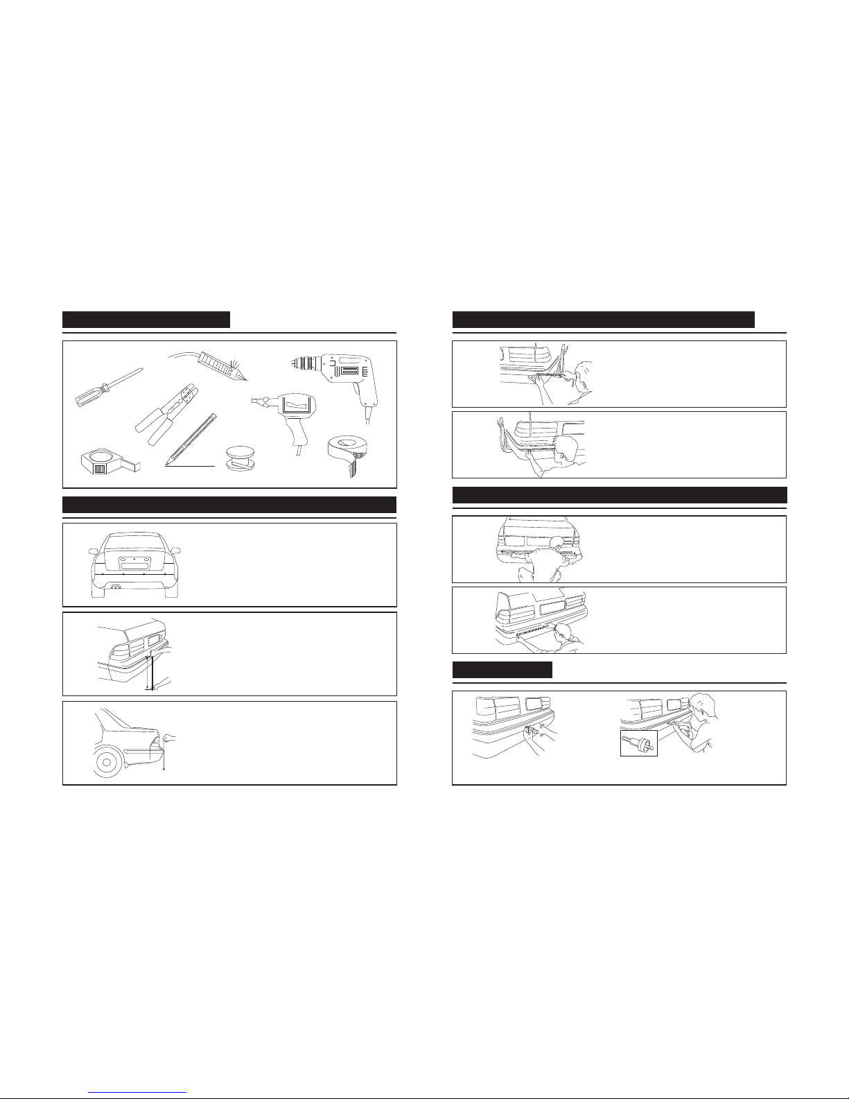
1.Choose right installation position for sensors
2. Select drilling position for sensor A & D
3. Select drilling position for sensor B & C
4. Locate the position and drill
5. Install the sensors and hide wires
6. Install the display
7. Install the control box
NOTE
3. Switch D5 used to choose Turn NO/OFF of the initial indication tone
System corresponding function
system enterring into reversing,no indication tone
3green+2yellow+red
3green+2yellow
3green+yellow
3green
2green
green
Bi...
Danger area
Alarm area
Safe area
Safe area
Safe area
Alarm sound
Bi...
Bi.Bi.
Bi..Bi..
Bi...Bi...
Bi....Bi....
none
Bi....Bi....
Bi...
Bars
3green+2yellow+2red
none
3green+2yellow+red
3green+2yellow
3green+yellow
3green
2green
green
Awareness
Danger area
Alarm area
Safe area
Danger area
Alarm area
Safe area
Safe area
Safe area
Min.obstacle distance(m)
When switch D6 is at the position "OFF”, the corresponding data for alarm mode and distance
Stage
Digital display(m)
1. The car must be in power-off, during the installation of the system
2. Its performance may be affected in following situation: heavy rain, gravel road, bumpy
road, sloping road and bush, very cold, hot or moist weather, or the sensor is covered
by snow. ice etc.
3. Switches among ultrasonic, electric wave, DC & AC and those among 24V, 12V
voltages may also effects its performance.
4. The sensors should be installed appropriate loose or tight.
5. Its performance will be effected if the sensors are fixed on metallic bumper.
6. Avoid installing the digital control box in places of great interference, such as vent-pipe,
wiring nearby.
7. Test the system to make sure it works normally before using.
8. This system is a reversing aid and the manufacturer will take no responsibility for any
accidents caused after the kit is installed.
control box system enterring into reversing mode, the buzzer beep 2 times to
the real distance.(Remark: if there is no spare tire or hook, turn theswitch D6 on “OFF” status)
the distance in the display is the same as the real distance
system corresponding function
the distance in the display is 0.2m less than the real distance
indicate the system is working normally
Min.obstacle distance(m)