mySmart MWS7 User manual

page
Section Contents Page
1 Dimensions 1
2 Description and operation 2
3 Wiringandxing 3
4 Installation/setting up 4
5 Programming 5
6 Wiringdiagrams 7
7 Detection patterns 10
8 Faultnding 12
9 Specication 12
10 Part numbers 12
80°
60°
40°
20°
0°
90°
10° 30°
50°
70°
90°
10°
30°
50°
70°
80°
60°
40° 20°
80°
60°
40°
20°
0°
90°
10° 30°
50°
70°
90°
10°
30°
50°
70°
80°
60°
40° 20°
MWS7
MicrowaveAisle Sensor
230VAC 10A
www.cpelectronics.co.uk
1. Dimensions
Contents
Product Guide
MWS7
Direct Dim Microwave Aisle Occupancy Detector

page 2
SENSITIVITY LUX
TIME RANGE
LOW HIGH DARK LIGHT
SHORT LONG NEAR FAR
www.cpelectronics.co.uk
MWS7
MicrowaveAisle Sensor
DSI/DALI (+)
DSI/DALI (-)
N
L/OUT
L
LVS (COM)
LVS (NC)
LVS (NO)
GND
EXT. LUX
GND
SLAVE
GND
SW. DOWN
SW. UP
JUMPERSETTINGS
Mains Relay (L/OUT)
LowVoltage Relay (LVS)
Perm. ON Auto.
ON/OFF Perm. OFF
EISOLATED SWITCH
INPUTS ONLY!
230V MAINS ONLY!
230VAC 10A
NOTUSED
RELAYOUT
24V MAX!
Jumpers
Used to set the states of the
switched live output and low
voltage relays in three different
states (‗Permanently ON‘,
‗Automatic ON/OFF‘ (controlled by
sensor detection) and
‗Permanently OFF‘). It is advised
that if a relay channel is not
being used it is set to OFF.
Mains
Power in and switched live out.
Earth Connection
MUST be connected.
Dimming Output
DSI/DALI output for
dimming control of
luminaires.
Not Used
Inputs/Outputs
Switch inputs (must
be isolated contacts)
and low voltage relay
outputs.
Manual adjusters
Sensor parameters
(sensitivity, lux, time
and range).
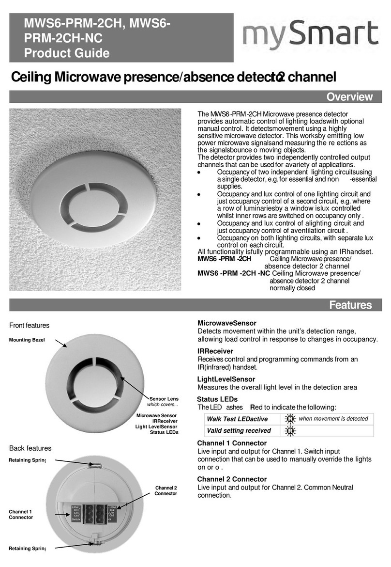
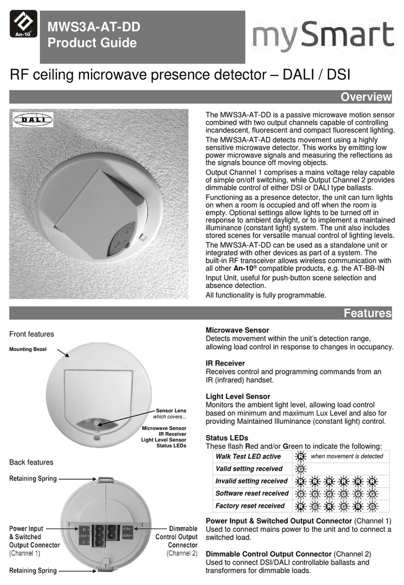
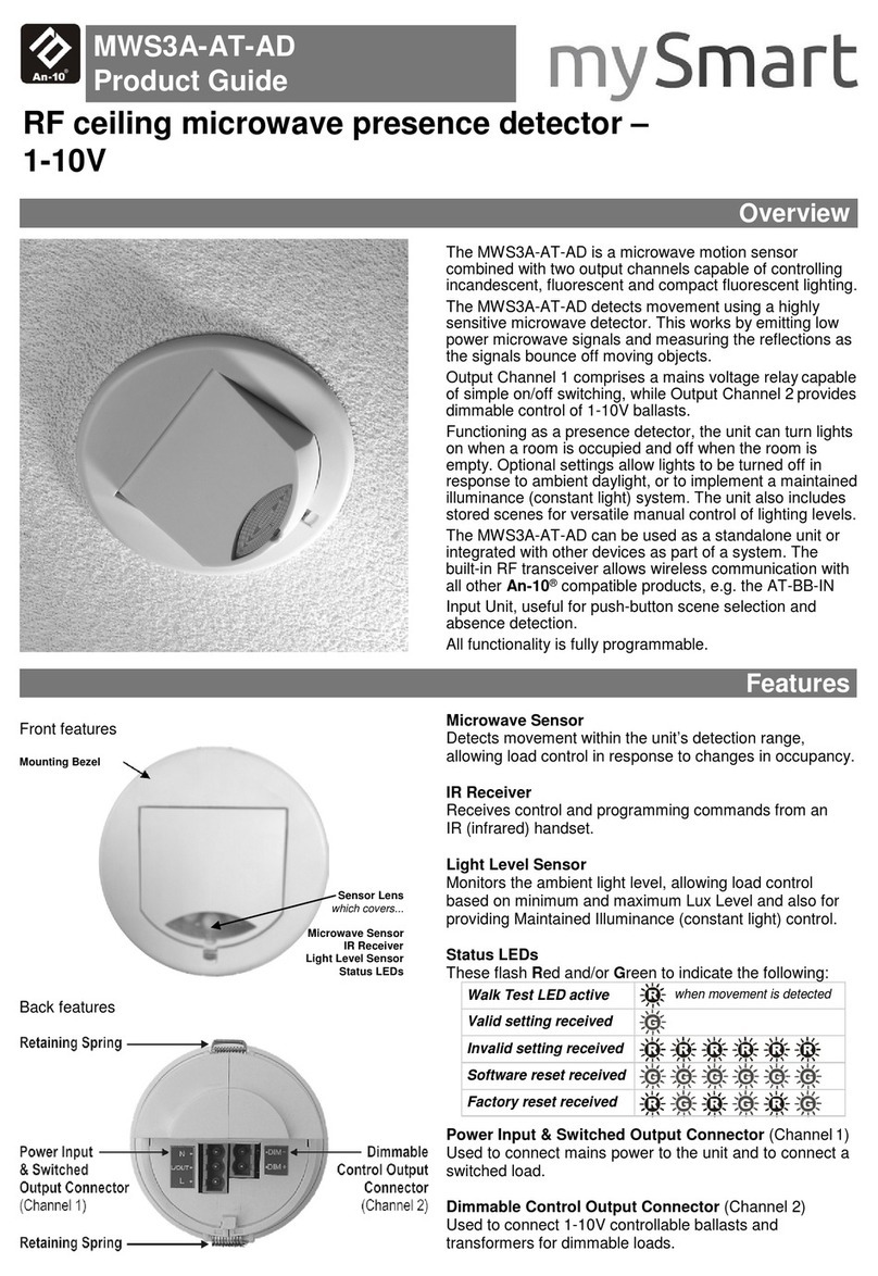
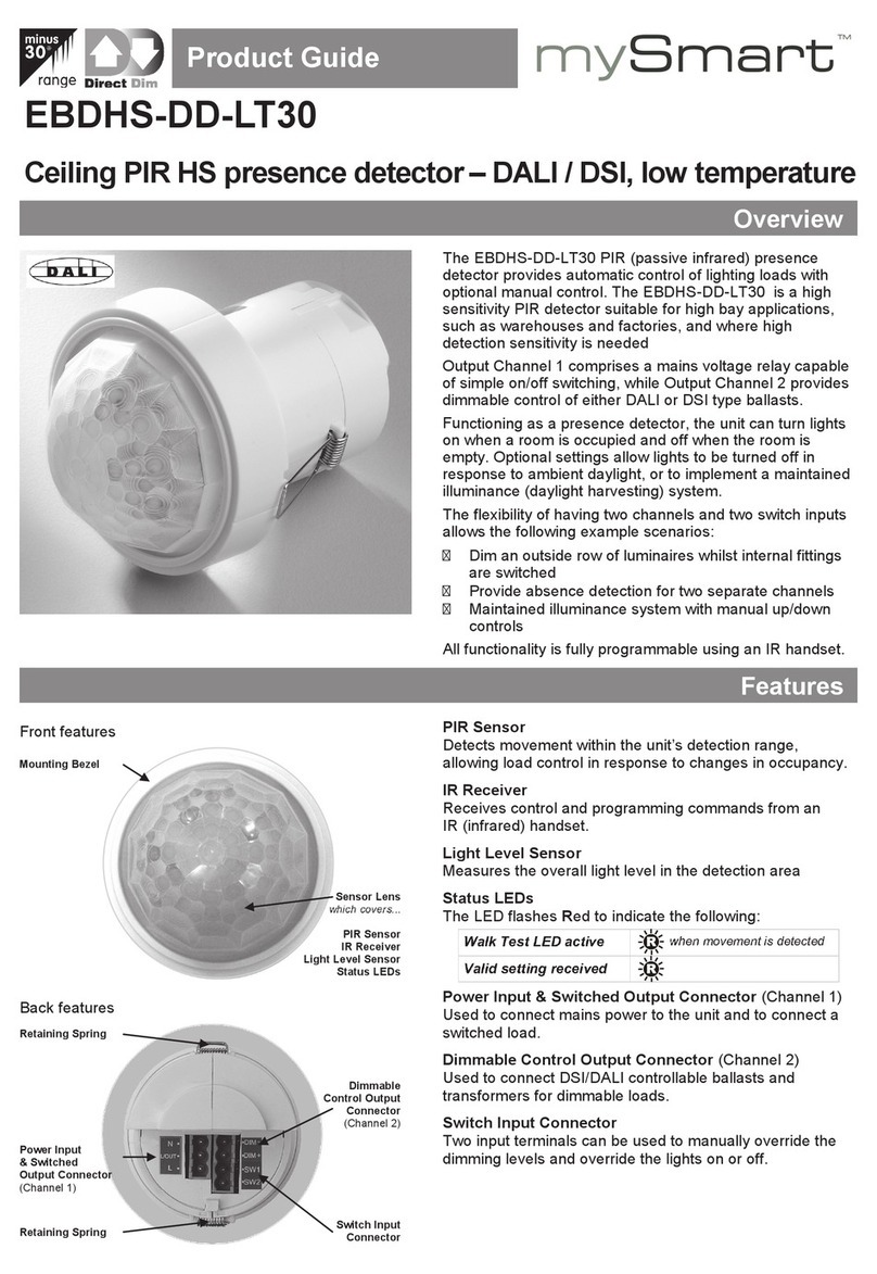
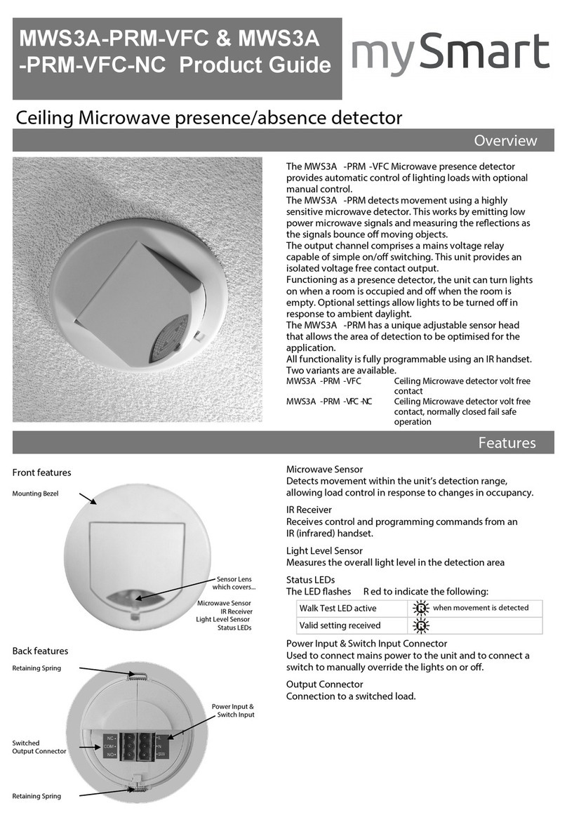
The MWS7 is a microwave occupancy detector that provides automatic control of lighting loads, and is
especially suited for warehouse applications. When a person or fork lift truck enters the aisle or corridor,
the sensor will turn the lights on, or raise the level of light output. After a pre-determined period, the lights
will turn off or dim down. The detector uses advanced microwave technology that allows the range of
detection to be accurately set, irrespective of whether the object is a person or a fork lift truck (a common
problem with other types of detector is that larger objects are picked up at longer distances, making
accurate setup impossible). A further benefit of the MWS7 is that it has good immunity to vibration.
Three output channels are provided:
Switching channel with a high power relay
Switching channel with a low voltage, low power isolated contact
Dimming channel capable of controlling up to 20 DSI or DALI ballasts
The detector has a built in photocell that measures the overall light level in the detection area. This can be
used to turn the lights on and off when natural light is sufficient, or on dimming systems to calculate the
correct output for the luminaires to achieve a preset lux level (maintained illuminance). The dimming
channel can also be used to set the luminaires to a ―standby‖ dim level rather than switching off
completely.
Input terminals are provided to give the following features:
Manual override of the dimming levels and switched outputs
Slave detector input—for use in dimming systems
External lux input—disables the output when there is sufficient natural light
Manual adjustments can be made to the sensitivity, range, lux and time settings using the physical
controls inside the sensor. Alternatively, an integral infra-red sensor in the unit allows the unit to be
programmed using the optional DD-LCDHS-LR programming handset, working to a range of 15m. This
gives complete flexibility over many of the operating parameters.
2. Description and Operation

page 3
Wire the products using the diagrams shown in section 6.
Do not exceed the maximum load and number of dimming connections as detailed in the specification
(section 9).
To control one or more loads from multiple sensors, wire two or more sensors in parallel using the Live,
Neutral and Switched Live (L/Out) connections only, or wire using the slave input terminals. The
dimming connection(s) from the luminaires must however only be wired to one of the MWS7 sensors.
The sensor should be sited so that the occupants of the room fall inside the detection pattern shown in
section 7. It is recommended for a single-sensor scenario that the sensor is sited near to one end of the
corridor or aisle and angled to provide maximum coverage of the desired area. For a multi-sensor
scenario, it is recommended that the sensors be placed near the centre of the corridor or aisle and
angled correctly to provide maximum coverage of the desired area.
Note that the fully adjustable detection range of the MWS7 provides a well-defined detection area that
extends radially from the sensor. It is therefore advantageous for the sensor to be mounted as low as
possible to provide the minimum range variation for objects of different heights (illustrated in section 7).
Note that the higher the sensor is installed, the effective detection range will become shorter.
Note also that the spread angle of the detection beam shown in section 7 is defined as the area of
maximum sensitivity. Detection is still possible outside these angles, but with a significantly reduced
sensitivity.
Installation Recommendations
Do not site so that the sensor is pointing at any fluorescent lighting
Site the sensor as far away as possible from the surface of metal objects
Site so that the sensor has an un-obstructed view of the desired coverage area
3. Wiring & Fixing

page 4
Warning. This device works at mains potential. Be sure to take care when working with electricity.
1. Isolate the mains supply to the circuit at the main consumer unit whenever working on the
connections to the sensor.
2. Make sure the load is connected and in working order.
3. Connect the sensor via the plug-in terminal blocks. Live supply to the Lterminal, load to the L/
OUT terminal and Neutral to the N terminal, all on the green terminal block. Earth to the E
terminal stud on the sensor body. Dimming and external input connections should be made via
the plug-in terminal blocks as required according to the applicable wiring diagrams shown in
section 6.
4. Two relay channels are provided, switched live and low voltage—if the channel is being used, set
the jumper to ―Auto‖, if it is not being used, set the jumper to ―OFF‖. To verify that the channel is
working, the jumper can be set to ―ON‖.
5. Set the sensitivity to maximum (fully clockwise) and range to the desired distance. Note that the
range varies between 5m (minimum) and 30m (maximum) when using the adjusters. Alternatively,
use the DD-LCDHS-LR to set these parameters.
6. Set the sensor to the appropriate angle then apply power and vacate the area for a minimum of 30
seconds while the sensor builds a ‗picture‘ of the area. Note that every time the sensor‘s range is
changed or the sensor is power-cycled, this step must be observed to ensure the proper operation
of the sensor.
7. Walk towards the sensor until the load comes on, to find the detection range. The use of the ‘Walk
Test‘ setting using the DD-LCDHS-LR will aid in finding this point by observing the flashing LEDs
within the sensor.
8. Tune the sensor range to the desired point by adjusting the range and repeating from step 6. Note
that a large metallic object may be detected up to 2m further away than a person - sufficient
adjustment must therefore be made to account for this.
9. Once the range has been set correctly, the sensitivity should be reduced as far as possible to a
point which still gives reliable detection at the same range.
10. For dimming applications, set the light output level by using the lux adjustment.
During operation the output level varies very gradually. However when the lux level is
changed the unit automatically enters setup mode: in this mode the output level varies
rapidly. After the setup time the unit reverts to normal
When adjusting the output, allow the output level to settle by changing very gradually
To disable the maintained illuminance function completely, set the lux level to maximum
11. Select the desired time-out using the adjuster or handset.
12. Other parameters can be set using the handset, see section 5 for details.
View of the adjusters inside the unit
SENSITIVITY LUX
TIME RANGE
LOW HIGH DARK LIGHT
SHORT LONG NEAR FAR
4. Commissioning

page 5
All the following functions can be programmed using the remote control DD-LCDHS-LR handset:
1. Detector Parameters (factory default in brackets):
1.1 Time adjustment (20 min) 10 seconds to 99 minutes time delay (select 0 for 10 second
delay –use for commissioning only).
1.2 Sensitivity On (9) Sensitivity level when the detector is already operational
adjustable between 1 (min.) and 9 (max.)
1.3 Sensitivity Off (9) Sensitivity level for switching the detector on –adjustable
between 1 (min.) and 9 (max.).
1.4 Range (m) (25) Sensor range (in metres). Can be set from 0-999, but only
the values 5-30 are effective. Other values are used for
sensor testing and debugging.
1.5 Power Up On (Y) Select No for a 10 second delay on start up. If Yes is selected,
there will be no delay on start up and the detector will always
power up detecting.
1.6 Walk Test (N) LEDs behind the detector lens will illuminate to show
movement has been detected (use for commissioning).
1.7 Disable Detector (N) Disables detection, leaving the relay output permanently off
with the dimming output operational. This mode is used when
the unit is for maintained illuminance only.
1.8 Factory Default Restores factory default settings.
2. Modes (factory default in brackets):
2.1 Channel Modes
2.1.1 Switch only Usually used for absence detection - in this mode the dimming
channel is not used.
2.1.2 Switch and dim together (default) The detector will switch and dim the lighting together.
2.1.3 Switch and dim separate Relay and dimming channels are controlled separately.
2.2 Switch Modes
2.2.1 2 position switch together (default) A single centre-biased retractive switch will be used to
control both channels together.
2.2.2 2 position switch separate A single centre-biased retractive switch will be used to
control only the dimming channel.
2.2.3 1 position switch together A single-position retractive switch controls both channels
together.
2.2.4 1 position switch separate Two single-position retractive switches, controlling the
channels separately.
3. Switching Channel 1 functions (factory default in brackets):
3.1 Presence detection Auto switch on with detection, auto off after movement ceases
(default) and time delay ends.
3.2 Absence detection Manual switch on, auto off after movement ceases and time
delay ends.
3.3 Switch level on (9) Lux level setting to prevent the luminaires being switched on if
the ambient light level is sufficient (adjustable between 1
and 9). The luminaires will always be switched on at level 9.
3.4 Switch level off (9) Lux level setting to switch the luminaires off during occupancy
if the ambient light level goes above the setting (adjustable
between 1 and 9). Level 9 will always keep the lights on.
5. Programming

page 6
4 Dimming Channel 2 functions (factory default in brackets):
4.1 Light level Maintained illuminance level (adjustable between 1 and 999). At 999 the
output will be always be at maximum.
4.2 Presence detection Auto switch on with detection, auto off after movement ceases and
(default) time delay ends.
4.3 Absence detection Manual switch on, auto off after movement ceases and time delay ends.
4.4 Switch level on (9) Lux level setting to prevent the luminaires being switched on if the
ambient light level is sufficient (adjustable between 1 and 9). The
luminaires will always be switched on at level 9.
4.5 Switch level off (9) Lux level setting to switch the luminaires off during occupancy if the
ambient light level goes above the setting (adjustable between 1 and 9).
Level 9 will always keep the lights on.
4.6 DSI (default) Selects DSI dimming.
4.7 DALI Selects DALI dimming.
4.8 Memorise (N) If this is set to Yes, the last manual lux level set will be memorised and
used as the new switch on level.
4.9 On value (99) Dimming output level when switched on (0-99).
4.10 Off value (0) Dimming output level when switched off (0-99). If set to anything other
than 0 the light will not switch off but maintain a background lighting level.
4.11 Fade value (10) After occupancy ceases, this dimming output level is loaded for the fade
time (adjustable between 0 and 99).
4.12 Fade mins (0) This is the time period (adjustable between 0 and 99 minutes) that the
luminaire will be held at the fade value before turning off. A value of 0
disables the fade function.
4.13 Max value (99) Maximum dimming output level (adjustable between 0 and 99).
4.14 Min value (1) Minimum dimming output level (adjustable between 0 and 99).
4.15 Speed on (40) Determines the dimming response speed after the setup time has
finished. Measured in 0.1 sec intervals.
4.16 Speed set (5) Determines the dimming response speed during the set up time.
Measured in 0.1 sec intervals.
4.17 Set seconds (120) Determines how long the dimming response set-up period lasts on power-
up or on setting change (adjustable between 1 and 999 seconds). This
enables the desired lux level to be achieved rapidly when the lights come
on, or during setup.
5 User Menu
5.1 Lux up Increase light level. Reverts when occupancy cycle complete.
5.2 Lux down Decrease light level. Reverts when occupancy cycle complete.
5.3 Scene up Steps up between 6 pre-defined scenes.
5.4 Scene down Steps down between 6 pre-defined scenes.
5.5 Scene# Select the individual scene, between 0 and 6 (1 = min. output; 2 = 10%;
3 = 25%; 4 = 50%; 5 = 75%; 6 = 100%).
5.6 Override on Permanently overrides the luminaire output on.
5.7 Override off Permanently overrides the luminaire output off.
5.8 Cancel Cancels the on or off override, returning the detector to normal operation.
5.9 Set If sent before using lux up or lux down, it will set the light level as in 4.1.
page 7
A diagram illustrating an example of all possible sensor connections can be seen below. The most
common connection scenarios are shown in sections 6.1 onwards.
www.cpelectronics.co.uk
MWS7
Microwave Aisle Sensor
ISOLATED SWITCH
INPUTS ONLY!
230VAC 10A
DIMMING
BALLAST
VOLTAGE-FREE CONTACTS
(OUTPUT TO SLAVE DETECTOR(S))
EXTERNAL
LUX SENSOR
SLAVE
INPUT
OVERRIDE SWITCH
(CENTRE-BIASED RETRACTIVE)
GND
EXT.LUX
GND
SW.UP
SW.DOWN
GND
SLAVE
DSI/DALI(+)
DSI/DALI(-)
JUMPERS
LIVE
NEUTRAL
NEUTRAL
L/OUT
[NOT USED]
EARTH
LUMINAIRE
(NON-DIMMING)
LUMINAIRE
(DSI/DALI DIMMING)
NEUTRAL
L/OUT
NOTE: All inputs
must be isolated
contacts.
6.1 Single channel switching
Switches the relay channels with occupancy and lux. An optional override switch allows the output to be
turned on and off manually. No dimming output.
www.cpelectronics.co.uk
MWS7
Microwave Aisle Sensor
ISOLATED SWITCH
INPUTS ONLY!
230VAC 10A
GND
SW.UP
SW.DOWN
LIVE
NEUTRAL
EARTH
LUMINAIRE
(NON-DIMMING)
NEUTRAL
L/OUT
JUMPERS
OVERRIDE SWITCH
(CENTRE-BIASED RETRACTIVE)
6. Wiring Diagrams

page 8
6.3 Two channel, switching and dimming
Switches the relay channels with occupancy and provides dimming control for DSI/DALI enabled
luminaires. An optional switch allows the outputs to be turned on and off and dimmed up and down.
Note that in this configuration the dimming luminaires can have a permanent live feed, with digital
switching via DSI/DALI. In this case, it is recommended that the relays are disabled using the jumpers.
6.2 Single channel, switching with external lux sensor
Switches the relay channels with occupancy and external lux sensor. An optional override switch allows
the output to be turned on and off manually. No dimming output. In this configuration the internal lux
sensor needs to be disabled by setting ―Switch level on‖ and ―Switch level off‖ to maximum.
This configuration is used when a separate lux sensor is needed to control multiple detectors. For example
in a warehouse, a lux sensor measures the ambient light for an area and disables the output for a number
of aisles.
www.cpelectronics.co.uk
MWS7
Microwave Aisle Sensor
ISOLATED SWITCH
INPUTS ONLY!
230VAC 10A
EXTERNAL
LUX SENSOR
GND
EXT.LUX
GND
SW.UP
SW.DOWN
JUMPERS
LIVE
NEUTRAL
EARTH
LUMINAIRE
(NON-DIMMING)
NEUTRAL
L/OUT
OVERRIDE SWITCH
(CENTRE-BIASED RETRACTIVE)
www.cpelectronics.co.uk
MWS7
Microwave Aisle Sensor
ISOLATED SWITCH
INPUTS ONLY!
230VAC 10A
DIMMING
BALLAST
GND
SW.UP
SW.DOWN
DSI/DALI(+)
DSI/DALI(-)
JUMPERS
LIVE
NEUTRAL
NEUTRAL
LIVE
EARTH
LUMINAIRE
(NON-DIMMING)
LUMINAIRE
(DSI/DALI DIMMING)
NEUTRAL
L/OUT
OVERRIDE SWITCH
(CENTRE-BIASED RETRACTIVE)

page 9
6.4 Two channel, switching and dimming with slave control
Switches the relay channels with occupancy and provides dimming control for DSI/DALI enabled
luminaires; with multiple connection to slave sensors.
Wire the system as in the diagram below. The master sensor provides the dimming signal. The voltage-
free output contact from multiple slave sensors is connected to the slave input of the master sensor.
This configuration is particularly useful for systems where the dimming fittings never turn off but provide a
minimum level of illuminance when the area is un-occupied (generally for safety reasons). DSI/DALI does
not allow multiple masters to generate the dimming signal, hence the use of one master and multiple
slaves. It is important in this configuration that the slave sensors are not connected to the DSI/DALI bus.
In this configuration it is recommended that the relays are disabled on the master using the jumpers.
MWS7
SLAVEDETECTOR
www.cpelectronics.co.uk
MWS7
Microwave Aisle Sensor
ISOLATED SWITCH
INPUTS ONLY!
230VAC 10A
DIMMING
BALLAST
SLAVE
INPUT
GND
SW.UP
SW.DOWN
GND
SLAVE
DSI/DALI(+)
DSI/DALI(-)
JUMPERS
SET TO ‘AUTO’
LIVE
NEUTRAL
NEUTRAL
LIVE
EARTH
LUMINAIRE
(NON-DIMMING)
LUMINAIRE
(DSI/DALI DIMMING)
NEUTRAL
L/OUT
OVERRIDE SWITCH
(CENTRE-BIASED RETRACTIVE)
MWS7
SLAVEDETECTOR

page 10
38°
20m
3m
ANGLED 12° DOWN
RANGE
CUT-OFF
OPTIMAL DETECTION
AREA
19.8m
38°
25m
7m
ANGLED 28° DOWN
RANGE
CUT-OFF
OPTIMAL DETECTION
AREA
DETECTION
‗DEAD‘ AREA
6.5m 17.5m 0.7m
True physical detection pattern of the MWS7:
Note: This is the optimal detection pattern of the microwave electronics within the MWS7 that gives the
best sensitivity. It is however possible for objects to be detected outside these angles shown, especially if
the object is large and metallic. The fully adjustable range cut-off area shown in subsequent diagrams still
applies however, regardless of the type and size of object.
Several scenarios are given below. Please contact our technical department for further information.
Example 1
Height: 3m
Range limit: 20m
Sensor angle: 12°
This scenario gives the best
definition of the range cut-off and
full area coverage, but is often not
achievable in real-life situations due
to the low mounting position.
Example 2
Height: 7m
Range limit: 25m
Sensor angle: 28°
Note that there is a detection ‗dead
area‘ under the sensor where
detection of, for example, a person
is far less likely. The range cut-off
now varies with height, due to the
cut-off being a radial distance from
the sensor.
7. Detection Patterns

page 11
Example 3
Height: 12m
Range limit: 25m
Sensor angle: 40°
This scenario would be used for mounting at height.
The detection ‗dead‘ area is larger and the range cut-off
is less defined (depending on the height of the object to
be detected).
38°
25m
12m
ANGLED 40° DOWN
RANGE
CUT-OFF
OPTIMAL DETECTION
AREA
DETECTION
‗DEAD‘ AREA
7.2m 14.7m 1.4m
38°
18m
38°
18m
12m
30m
8m
ANGLED
60° DOWN
4m
Example 4
Height: 12m
Range limits: 18,m, 18m (30m coverage)
Sensor angles: 60°, 60°
This scenario provides coverage of a double-ended
aisle using two sensors. Note: A minimum
separation of 4m between sensors recommended.
Example 5 (above) & 6 (below)
Height: 12m
Range limits: Setup 5: 18m, 18m, 25m (50m coverage); Setup 6: 25m, 18m, 18m, 25m (70m coverage)
Sensor angles: Setup 5: 60°, 60°, 44°; Setup 6: 44°, 60°, 60°, 44°
These scenarios again provide coverage of double-ended aisles, but of greater lengths.
38°
25m
38°
18m
38°
18m
12m
50m
8m
ANGLED
60° DOWN
4m
ANGLED
44° DOWN
11m
4m
38°
25m
38°
25m
38°
18m
38°
18m
12m
70m
8m
ANGLED
60° DOWN
4m ANGLED
44° DOWN
11m
4m4m
11m
ANGLED
44° DOWN
Example 7—not recommended
Note: It is NOT recommended for sensors to be mounted in this
manner with the sensor faces pointing towards each other, as
interference between the sensors may occur.

LOAD
Channel 1 (switching):
10A of lightingand/or ventilation including incandescent, uorescent, compact uorescent, low voltage (switch primary of
transformer) using the switched live L/OUT terminal
1A 24VDC using the low voltage relay output
Channel 2 (dimming):
20 x dimming ballasts (DSI orDALI)
SUPPLY VOLTAGE 220-240Volts AC 50 Hz
TIME OUT PERIOD Adjustable 10 seconds to 99minutes
LIGHT LEVEL Lightto dark
FIXING METHOD Surfacexing using integral mounting bracket
TERMINAL CAPACITY 1.5mm2
MATERIAL Polystyrenebox, steel mounting bracket withnylonscrews.
TYPE Class 2
TEMPERATURE -10°C to35°C
SAFETY The microwave radiation emitted bytheseunits is exteremelylow power.
Ata distance of> 50mm the power density is <6% of the ANSI
IEEEC95.1 –1991 recommended microwave powerdensity.
Ata distance of 5mmfrom the unit it is <84% ofrecommendedpower density.
CONFORMITY EMC -89/336/EEC
LVD -73/23/EEC
MWS7 Microwave presence detector
MWS7/PRG Microwavedetector pre -commissioned (contact sales department)
DD-LCDHS -LR IR remote control programming handset with LCD screen,long range operation
LIGHTS DO NOT COME ON
Check to see ifthelive supplyto the circuit is
good. Strap acrossthe L and L/Out terminal to
check thattheload turns on when powered.
Check theswitch -on luxlevel setting. Increase
thesetting to allow the controller to turn on at a
higher ambient natural light level. Check the
external lux sensor is in sucient darkness(if
used).
Check therange is set to an appropriate distance
andthe sensitivity is nottoolow.
LIGHTS DO NOT GO OFF
Ensurethatthe areaisleft unoccupied for a
greatertime period than thetime -outperiod set
using theadjuster or the handset.
Make sure thatthe sensor is notmounted on,
adjacent to or looking at surfaces thatare
obviouslymoving.
Theunit may pick upmovement through glass,
thin partitions or walls. Turn thesensitivitydown
byusing the nger dial or the handset.
Ensurethat two or more sensors are notpointed
atormounted inthe near vicinity of each other.
Theunit may pick upmovement that occurs
behind the sensor. Turn the sensitivity down by
using theadjuster or the handset.
8. Fault Finding
9. Specication
10. Part Numbers
page 12
Due to our policy of continual product improvement mySmart reserves the right to alter the specification of this product without prior notice.
Unit 16
1 Talavera Road
Macquarie Park, NSW 2112
Australia
T: 1300 697 627
F: (02) 9887 1333
www.mysmart.com.au
IMPORTANT NOTICE!
This device should be installed by a qualified
electrician inaccordance with the latest edition
of the AS/NZS Wiring Rules and any applicable
Building Regulations.
Table of contents
Other mySmart Security Sensor manuals

mySmart
mySmart MWS3A-AT-AD User manual

mySmart
mySmart EBDHS-DD-LT30 User manual

mySmart
mySmart MWS6-PRM User manual

mySmart
mySmart MWS3A-PRM-VFC & MWS3A-PRM-VFC-NC User manual

mySmart
mySmart MWS6-PRM-LV User manual

mySmart
mySmart EBDSPIR-PRM-IP User manual

mySmart
mySmart MWS6-PRM-2CH User manual

mySmart
mySmart MWS3A-AT-DD User manual

mySmart
mySmart MWS3A-PRM-2CH User manual

mySmart
mySmart MWS3A-PRM-LV User manual