Bosch Security Systems, Inc. | 3
LED illumination Switch setting
Table 5.1: Switch settings
5.2 | Look-down and Pet
immunity switch
NOTICE!
To preserve battery life, LED
indications are visible only after
3 minutes have passed since the
previous alarm restoral when the
LED switch is set to on.
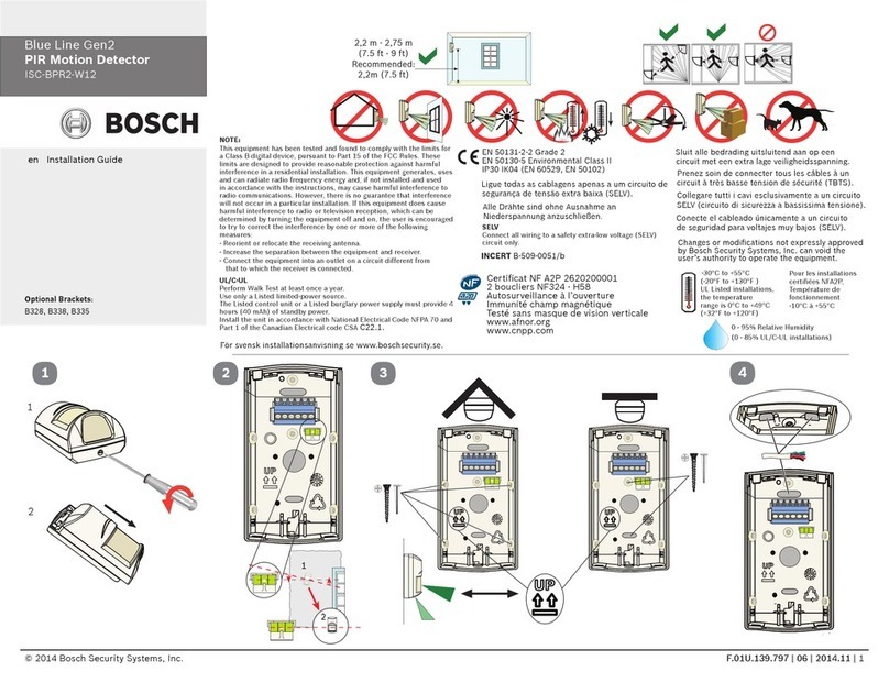
The motion detector has a rotary switch to
enable or disable the look-down zone and pet
immunity. Refer to Figure 5.2.
• Enable the look-down zone by turning the
dial to the right. Use this to detect motion
in the area underneath the device. This
also disables pet immunity and increases
sensitivity by approximately 20% for use in
higher security applications.
• Disable the look-down lens to avoid false
alarms from objects moving in the area
underneath the device. This also enables
pet immunity in applications with pets.
2
ON
OFF
2
ON
OFF
ON
OFF
2LED
NOTICE!
Product must be walk tested at
least once each year.
NOTICE!
If the controller does not discover
the motion detector within three
minutes, the motion detector exits
pairing mode. The motion detector
restarts pairing when motion is
detected.
7 | Pairing process
The unit powers up when batteries are
installed. Slide the detector body onto the
mounted base.
Pairing the detector with the controller:
1. The red LED lights for two seconds,
then the detector enters pairing mode.
2. The red LED flashes three times
every five seconds until the controller
discovers the detector. Complete the
next step within three minutes to limit
battery consumption.
3. As soon as the detector enters pairing
mode, go to the controller and complete
the pairing process according to the
controller manufacturer’s instructions.
8 | Complete the setup
Follow the instructions below to walk test the
motion detector.
8.1 | Walk test the detector
8.2 | Complete the walk test
1. Once you complete the walk test, do not
disturb the detector’s coverage pattern
for 90 seconds.
2. After 80 seconds, the detector flashes
red to indicate the walk test time is
about to expire.
3. After flashing for 10 seconds, the
detector exits walk test mode.
The battery tray in this device has two
compartments. The device requires only one
battery to operate (included) and is already
installed. You can add a second battery (not
included) to extend battery life. If installing
for the first time, remove the battery
cardboard insert.
To install the batteries:
1. Slide the battery tray into the detector
body using two fingers with the finger
cavity facing out. Be certain to slide the
tray in until the top of the tray is flush
with the top of the detector body and
you feel it “click” into position. The LED
stays lit for 2 seconds immediately after
the battery “clicks” into place. Refer to
battery insertion sequence in Figure 6.1.
Figure 5.2: Look-down adjustment
6 | Battery installation
Use a smart phone and scan the following QR
code for additional information on walk test.
1.
2.
+
+
++
+
++
Figure 6.1: Battery insertion
I
+
I
+
+
I
3.
4.
“Click”
5.
2 sec
9 | Operation and maintenance
In the normal operating mode, an alarm is
transmitted only after three minutes have
passed since the previous alarm restoral.
This three minute lockout time reduces
unnecessary RF transmissions in high traffic
areas thereby extending battery life.
It is recommended to clean the detector lens
periodically using a moisten cloth dipped in
water.
Performing the walk test:
1. Remove the detector body from the base
then slide it back on. This starts a 15
second timer. The LED flashes red during
this time. As soon as the LED flashing
has completed, walk test mode starts.
2. Once started, the detector remains in
walk test mode for as long as it senses
motion. If no motion is detected for 90
seconds, the unit exits walk test mode.
Be sure to begin walk testing within the
90 second window.
3. Start the walk test from the farthest
point of the sensor’s coverage pattern.
4. During the walk test, observe the LED
colors.
• Red indicates PIR activity
NOTICE!
Verify your home control system or
security control panel is powered
up and operational before
beginning the pairing process.
NOTICE!
The LED is active during the
pairing process and walk test
regardless of the setting of Dip
switch 2.
