manuals.online logo
Brands
  1. Home
  2. •
  3. Brands
  4. •
  5. Myson
  6. •
  7. Thermostat
  8. •
  9. Myson MPRT RF User manual

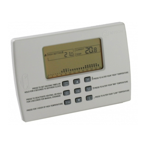
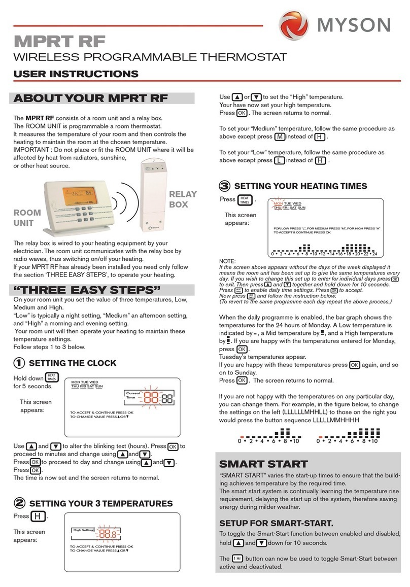
Myson MPRT RF User manual

OK
H
M
L
HEAT
TIMES
PRESS TO ALTER YOUR HEATING TIMES
PRESS TO DEACTIVATE HEATING, OR HOLD
FOR 5 SECONDS FOR MANUAL OVERRIDE
PRESS FOR 1 HOUR OF HIGH TEMPERATURE
PRESS TO ALTER YOUR “HIGH” TEMPERATURE
PRESS BOTH TOGETHER TO SET/VIEW CLOCK
PRESS TO ALTER YOUR “MID” TEMPERATURE
PRESS TO ALTER YOUR “LOW” TEMPERATURE
OFF
MAN
1 Hr
High Setting
Current
Temp
0 2 4 6 8 10 12 14 16 18 20 22 24
+
MPRT RF
WIRELESS PROGRAMMABLE THERMOSTAT
The MPRT RF consists of a room unit and a relay box.
The Room Unit senses the room temperature and if heat is called
for, it transmits a radio signal to the relay box which in turn
activates the heating.
WIRING THE RELAY BOX.
The relay box is powered by 230V ac, 50Hz.
The figure below shows both low voltage and 230V ac wiring op-
tions for switching the heating equipment.
WARNING: Installation and maintenance to be carried out
only by suitably qualified personnel and in accordance with cur-
rent IEE wiring regulations.
ROOM UNIT
RELAY BOX
INSTALLATION INSTRUCTION
C
-1 L N
C 1 L N
O
C
C 1 L N
N
L
N230V ac, 50 Hz
input power
input power
To heating
equipment
230V ac, 50 Hz
L
O
C
HEATING
EQUIPMENT
C
-1 L N
C 1 L N
O
C
C 1 L N
N
L
N230V ac, 50 Hz
input power
input power
To heating
equipment
230V ac, 50 Hz
L
O
C
HEATING
EQUIPMENT
Volt Free/Low Voltage Switching of
Heating Equipment.
C
-1 L N
C 1 L N
O
C
C 1 L N
N
L
N230V ac, 50 Hz
input power
input power
To heating
equipment
230V ac, 50 Hz
L
O
C
HEATING
EQUIPMENT
230V ac Switching of Heating Equipment
ACTIVATING THE ROOM UNIT
Release the cover from the base by pressing at the arrow.
Remove the plastic strip which is preventing the battery connec-
tion in the battery compartment.
The LCD should display as shown below.
Reassemble the cover to the base.
PRESS HERE
LOCATING THE ROOM UNIT
The room unit can be mounted on its plastic stand and placed on
a sideboard or other item of furniture. Alternatively it can be wall
mounted using the two screws provided.
WHEREVER the Room Unit is mounted/used it should be out of
direct sunlight, out of draughts, and clear of any heat source (e.g.
radiators, fires or electronic equipment). For optimum use the unit
should be sited between 1 and 1.5metres from the floor.
MON
TUE WED
THU FRI SAT SUN
High Setting Current
Temp
0 2 4 6 8 10 12 14 16 18 20 22 24
MON TUE WED THU FRI SAT SUN
0 2 4 6 8 10 12 14 16 18 20 22 24
High Setting
Current
Time
MON TUE WED
THU FRI SAT SUN
TO ACCEPT & CONTINUE PRESS OK
TO CHANGE VALUE PRESS OR
TO ACCEPT & CONTINUE PRESS OK
TO CHANGE VALUE PRESS OR
FOR LOW PRESS “L”, FOR MEDIUM PRESS “M”, FOR HIGH PRESS “H”
TO ACCEPT & CONTINUE PRESS OK
Low Setting
Current
Temp
0 2 4 6 8 10 12 14 16 18 20 22 24
12 14 16 18 20 22 24
SAT SUN SMART START
12 14 16 18 20 22 24
SAT SUN SMART START
0 2 4 6 8 10 0 2 4 6 8 10
0 2 4 6 8 100 2 4 6 8 10
OK
H
M
L
HEAT
TIMES
PRESS TO ALTER YOUR HEATING TIMES
PRESS TO DEACTIVATE HEATING, OR HOLD
FOR 5 SECONDS FOR MANUAL OVERRIDE
PRESS FOR 1 HOUR OF HIGH TEMPERATURE
PRESS TO ALTER YOUR “HIGH” TEMPERATURE
PRESS BOTH TOGETHER TO SET/VIEW CLOCK
PRESS TO ALTER YOUR “MID” TEMPERATURE
PRESS TO ALTER YOUR “LOW” TEMPERATURE
OFF
MAN
1 Hr
High Setting
Current
Temp
0 2 4 6 8 10 12 14 16 18 20 22 24
(1.0 - 1.5) m
MYSON CONTROLS
MYSON LTD., EASTERN AVENUE,
TEAM VALLEY, GATESHEAD,
TYNE & WEAR, NE11 0PG
SALES OFFICE No. 0845 402 3434
IN ACCORDANCE WITH OUR POLICY OF CONTINUAL PRODUCT IMPROVEMENT WE
RESERVE THE RIGHT TO AMEND THE SPECIFICATION OF THESE PRODUCTS WITHOUT
PRIOR NOTIFICATION.
LINKING THE ROOM UNIT TO THE RELAY BOX
Place the relay box in linking mode by holding down the button
on the relay box for 4 seconds.
The green LED will light continuously indicating that the relay box
is ready for a configuration signal. With the room unit close to the
relay box, hold down for 10 seconds. The message
appears and the bar graph takes on a wavy pattern indicating that the
room unit is transmitting its configuration address to the relay box.
The link has been successfully established when the green LED
blinks regularly at about 4 times per second.
Press on the room unit to exit linking mode.
Note: The range of the room unit can be tested during the linking
procedure by taking it successively further away from the relay box
and verifying that the green LED continues to blink regularly at
about 4 times per second.
SETUP FOR SMART-START.
To toggle the Smart-Start function between enabled and disabled,
hold and down for 10 seconds. The button can now be
used to toggle Smart-Start between active and deactivated.
CONFIGURING FOR WEEKLY OR
DAILY TIMING.
To toggle between weekly or daily time settings, hold and
down for 10 seconds. The button can now be used to toggle
between enabled and disabled.
CONFIGURING FOR GAS OR OIL
To toggle between Oil or Gas hold and down for 10
seconds. The L button can be used to toggle between
Oil and Gas.
RELAY BOX OPERATION.
KEY TO LEDS
Yellow LED Lighting = Manual Mode.
Yellow LED not Lighting = Automatic Mode.
Red LED Lighting = Heating On.
Red LED not Lighting = Heating Off.
Green LED Lighting = Waiting on a configuration signal
from the room unit.
Green LED Quick Blink = Linking to room unit.
Green LED Slow Blink =
USING MANUAL MODE.
Press to force heating on.
Press to cease forcing heating on.
Press again to return to Auto Mode.
TECHNICAL DATA: ROOM UNIT.
Precision of measured temperature: 0.1oC
Set temperature range: 6oC to 32oC
Electrical Protection: Class II
Ingress Protection: IP30
Batteries: 3 X LR6 AA 1.5V alkaline batteries
Battery Life: 2 years approx.
Radio Frequency: 433.92 MHz, < 10mW
Statutory Compliance: R&TTE 1999/5/CE
Pollution Situation: Normal
TECHNICAL DATA: RELAY BOX.
Operating Temperature: 0oC to 50oC
Electrical Protection: Class II
Ingress Protection: IP44
Power Supply: 230V ac +/-10%, 50Hz
Radio Frequency: 433.92 MHz, <10mW
Communication Range: 30m in residential environments
Output Relay Rating: 12A 250Vac
Statutory Compliance: EMC 89/336/EEC,
LVB/2006/95/EEC
Pollution Situation: Normal
Software Class: A
PRESS HERE
OK
H
M
L
HEAT
TIMES
OFF
MAN
1 Hr
OK
H
M
L
HEAT
TIMES
OFF
MAN
1 Hr
OK
H
M
L
HEAT
TIMES
OFF
MAN
1 Hr
OK
H
M
L
HEAT
TIMES
OFF
MAN
1 Hr
OK
H
M
L
HEAT
TIMES
OFF
MAN
1 Hr
OK
H
M
L
HEAT
TIMES
OFF
MAN
1 Hr
OK
H
M
L
HEAT
TIMES
OFF
MAN
1 Hr
OK
H
M
L
HEAT
TIMES
OFF
MAN
1 Hr
ERROR - Check the following:
The room unit batteries are not exhausted.
The radio transmission range is not excessive.
The room unit is not within 50cm of an
apparatus emitting electrical interference.
No other apparatus is continuously
transmitting on the 433.92MHz radio fre-
quency.
PRESS HERE
PRESS HERE
PRESS HERE
SC2388 Revision 2
OK
H
M
L
HEAT
TIMES
OFF
MAN
1 Hr
OK
H
M
L
HEAT
TIMES
OFF
MAN
1 Hr

Other Myson Thermostat manuals

Myson Unisenza Plus Thermostat User manual

Myson

Myson Unisenza Plus Thermostat User manual

Myson MPRT User manual

Myson

Myson MPRT User manual

Myson Touch 2 WiFi User manual

Myson

Myson Touch 2 WiFi User manual

Myson MPRT RF User manual

Myson

Myson MPRT RF User manual

Myson MPRT MS User manual

Myson

Myson MPRT MS User manual

Myson MRT1 User manual

Myson

Myson MRT1 User manual

Myson TOUCH4 User manual

Myson

Myson TOUCH4 User manual

Myson 63050507401 User manual

Myson

Myson 63050507401 User manual

Myson Touch RS User manual

Myson

Myson Touch RS User manual

Myson REMOTE ROOM THERMOSTAT CONTROL User manual

Myson

Myson REMOTE ROOM THERMOSTAT CONTROL User manual

Popular Thermostat manuals by other brands

KMC Controls CTE-1005 installation guide

KMC Controls

KMC Controls CTE-1005 installation guide

AC International CT0-7TC-32 instruction manual

AC International

AC International CT0-7TC-32 instruction manual

Samson STM 5343 Mounting and operating instructions

Samson

Samson STM 5343 Mounting and operating instructions

nvent NUHEAT Signature quick start guide

nvent

nvent NUHEAT Signature quick start guide

First ELTHERM AT8 user manual

First

First ELTHERM AT8 user manual

SyxthSense DAEA80 quick start guide

SyxthSense

SyxthSense DAEA80 quick start guide

Polypipe UFH8ZMP user manual

Polypipe

Polypipe UFH8ZMP user manual

Venstar ACC0433 owner's manual

Venstar

Venstar ACC0433 owner's manual

Grasslin famoso 1000 rf user manual

Grasslin

Grasslin famoso 1000 rf user manual

Trane TCONT402AN32DA Installer's guide

Trane

Trane TCONT402AN32DA Installer's guide

Honeywell RTH9590 user guide

Honeywell

Honeywell RTH9590 user guide

CAME PSRT01 manual

CAME

CAME PSRT01 manual

SwannOne ZEN-01 quick start guide

SwannOne

SwannOne ZEN-01 quick start guide

Honeywell VisionPRO IAQ operating manual

Honeywell

Honeywell VisionPRO IAQ operating manual

Perry Electric 1TX CR028WIFI Installation and use manual

Perry Electric

Perry Electric 1TX CR028WIFI Installation and use manual

Aube Technologies TH108 user guide

Aube Technologies

Aube Technologies TH108 user guide

LATICRETE STRATA_HEAT Easy setup guide

LATICRETE

LATICRETE STRATA_HEAT Easy setup guide

Danfoss CF-RP 088U0211 instructions

Danfoss

Danfoss CF-RP 088U0211 instructions

manuals.online logo
manuals.online logoBrands
  • About & Mission
  • Contact us
  • Privacy Policy
  • Terms and Conditions

Copyright 2025 Manuals.Online. All Rights Reserved.