1.0 General Information
2.0 Controls Switch
lPlease read these instructions thoroughly before proceeding
with the installation.
lThis remote control thermostat is suitable for operating one
KICKSPACE®fan convector only.
lThis kit must be installed by a qualified electrician.
lThis accessory pack is designed to convert a KICKSPACE®fan
convector from integral switch controls providing off, high
and low fan speed selection and summer / winter option, to
a remote wall mounted control of the same function with the
addition of a room thermostat.
lThis pack contains a 5 metre length of cord specially
terminated and colour coded for the application. No other
cord can be used to connect the remote control switch to the
fan convector.
1. Locate a convenient wall space above the KICKSPACE®fan
convector that will permit connection via the 5 metre cord
supplied. The control should be mounted approximately 1.5
metres above floor level away from sources of moisture and
heat. It must be situated away from draughts and not in
areas affected by heat from radiators, ovens, windows etc.
as shown in fig 1.
2. Remove the control knob, undo the side screw and take off
the front cover.
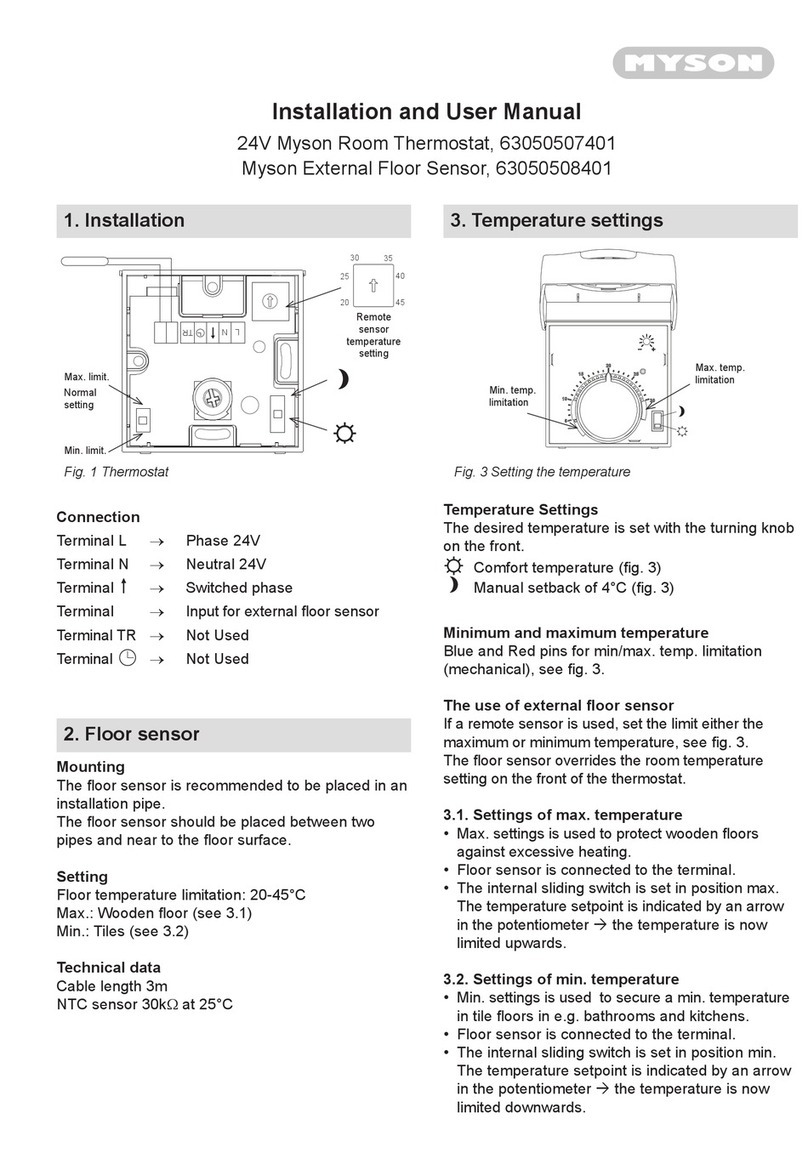
3. The thermostat can be fixed either to a standard electrical
back box or directly onto the wall.
4. Feed the electrical cables through one of the 2 rectangular
holes in the back of the thermostat and using the end without
crimp terminals, connect the 5 metre cord to the remote
switch as per the wiring diagram below. Use the linkwires
supplied with this kit to connect terminals 4 & 5 and 6 & 7 as
per the wiring diagram, see fig 4.
5. The cord must be installed in accordance with current codes
of practice. It should preferably be recessed, but if exposed,
it shall be protected by suitable conduit. Run the cord via the
prepared route to the KICKSPACE®fan convector.
6. Replace front cover, fix with side screw and replace the
control knob with soft manual pressure.
Important: Isolate the electricity supply to the
KICKSPACE®fan convector. Do not reinstate the
supply until the installation has been completed in
accordance with these instructions.
KICKSPACE®500, 600 & 800 Remote Room Thermostat Control Switch Instructions
3.0 KICKSPACE®Unit
1. Remove the fixing screw and lift the tabs holding the
electrical connections cover in place.
2. Locate the fan speed switch on the front of the control panel.
Disconnect the red and yellow wires from the switch and also
at the fan. Discard these wires.
3. Disconnect the brown wire from the back of the fan speed
switch.
4. Cut the blue wire from the fan motor close to the summer /
winter switch. Cut the incoming mains neutral wire close to
the summer winter switch. Connect the mains neutral wire to
the fan neutral using the 1 way terminal block supplied with
this kit. Discard the remaining blue wires attached to the low
limit thermostat and the summer/winter switch.
5. A cable clamp bush is supplied with the remote control kit.
Route the cable through the hole in the side panel, and make
the following connections:
Yellow lead: Connect to the low fan speed connector, see fig 2.
Red lead: Connect to the high fan speed connector, see fig 2.
Brown lead: Connect to the brown wire disconnected
from the fan speed switch.
Green / Yellow: Connect to the chassis earth tag.
Blue lead: Connect to low limit thermostat.
Fit the cable clamp bush onto the cable ensuring that internal
wiring is not too tight, and that it does not contact the
copper heat exchanger pipe-work.
6. Refit the electrical compartment cover onto the unit.
7. Reinstate the electrical supply to the KICKSPACE®fan
convector.
Low Terminal (Yellow)
High Terminal
(Red)
Common
Terminal
(Blue)
Fig. 1 Control Positioning
Fig. 2 Motor Connections
REMOTE ROOM THERMOSTAT CONTROL SWITCH INSTALLATION INSTRUCTIONS
01.01.2014, ISSUE 2
26556 Kickspace Remote Instructions FOR WEB 17/01/2014 12:12 Page 3
