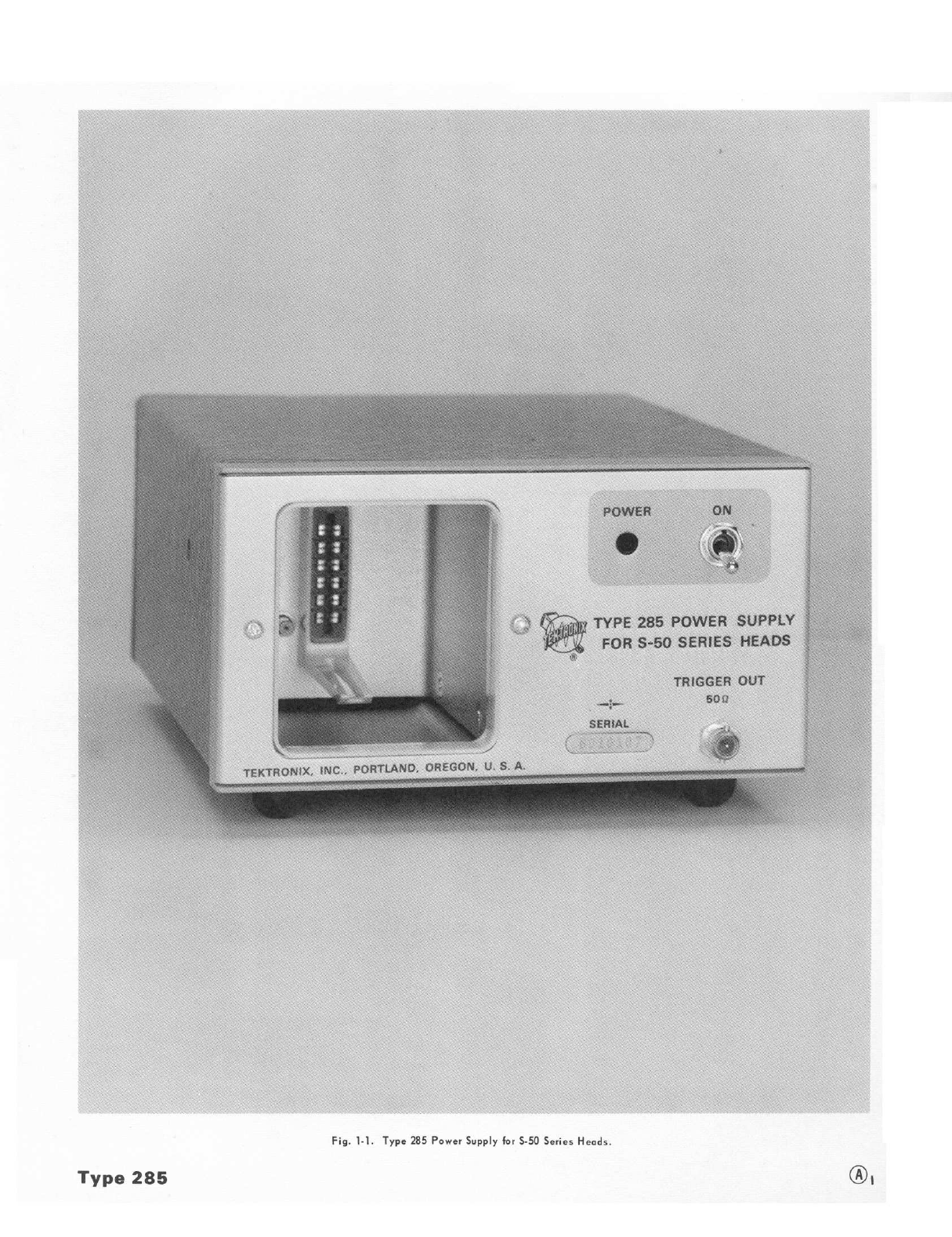
Tektronix 285 User manual
Other Tektronix Power Supply manuals

Tektronix
Tektronix TM 515 User manual

Tektronix
Tektronix PS280 User manual

Tektronix
Tektronix PWS2185 Use and care manual

Tektronix
Tektronix Keithley 2231A-30-3 Installation and operation manual

Tektronix
Tektronix 1103 User manual

Tektronix
Tektronix 620-0295-00 User manual

Tektronix
Tektronix KEITHLEY 2200 Series Owner's manual

Tektronix
Tektronix PS2520 User manual

Tektronix
Tektronix PWS4205 Operating and maintenance manual

Tektronix
Tektronix PS 503 User manual

Tektronix
Tektronix PS 503A User manual

Tektronix
Tektronix Keithley 2268 Series User manual

Tektronix
Tektronix PS 501 User manual

Tektronix
Tektronix PWS4000 Series User manual

Tektronix
Tektronix Keithley 2260B Series User manual

Tektronix
Tektronix Keithley 2260B Series User manual

Tektronix
Tektronix PS 5004 User manual

Tektronix
Tektronix PWS2185 User manual

Tektronix
Tektronix Keithley 2260B Series Owner's manual

Tektronix
Tektronix TM 515 User manual