Fortinet FortiGate-6000F Series Parts list manual

FortiGate-6000F System Guide
FortiGate-6000F Series

FORTINET DOCUMENT LIBRARY
https://docs.fortinet.com
FORTINET VIDEO GUIDE
https://video.fortinet.com
FORTINET BLOG
https://blog.fortinet.com
CUSTOMER SERVICE & SUPPORT
https://support.fortinet.com
FORTINET TRAINING & CERTIFICATION PROGRAM
https://www.fortinet.com/support-and-training/training.html
NSE INSTITUTE
https://training.fortinet.com
FORTIGUARD CENTER
https://fortiguard.com/
END USER LICENSE AGREEMENT
https://www.fortinet.com/doc/legal/EULA.pdf
FEEDBACK
Email: techdoc@fortinet.com
January 21, 2021
FortiGate-6000F 6.4.2 System Guide
01-642-464766-20210121

TABLEOFCONTENTS
Change log 5
FortiGate-6000F hardware description 6
Front panel interfaces 7
Interface groups and changing data interface speeds 7
Front panel LEDs 8
Front panel connectors 9
Supported transceivers 10
Console port 11
Connecting to the CLI of an individual FPC 12
NMI switch and NMI reset commands 12
FortiGate-6000F back panel 13
FortiGate-6000F schematic 13
FortiGate-6000F hardware information 15
Shipping components 15
Optional accessories and replacement parts 15
Physical description of the FortiGate-6000F 15
FortiGate-6000F hardware generations 16
Cooling fan trays 16
FortiGate-6000F AC power supply units (PSUs) 17
Connecting generation 2 FortiGate-6000F PSUs to high line AC power 18
Connecting generation 1 or 2 FortiGate-6000F PSUs to low line AC power 19
AC PSU LED states 19
Connecting FortiGate-6000F PSUs to AC power 20
Hot swapping an AC PSU 20
Connecting the FortiGate-6000F to ground 20
FortiGate-6000F hardware assembly and rack mounting 22
Cautions and warnings 22
Cooling air flow and required minimum air flow clearance 22
FortiGate-6000F four post rack-mount installation 23
Installation steps 23
Sliding the FortiGate-6000F into the rack 25
Removing the FortiGate-6000F from a four-post rack 27
Surface-mount installation 28
Installing QSFP28, SFP28, SFP+, and SFP transceivers 28
To install transceivers 29
Getting started with FortiGate-6000 30
Confirming startup status 31
Default VDOM configuration and configuring the management interfaces 31
Changing data interface network settings 32
Adding a password to the admin administrator account 32
Resetting to factory defaults 32
Restarting the FortiGate-6000 33
FortiGate-6000F System Guide 3
Fortinet Technologies Inc.

Fortinet Technologies Inc.
Managing individual FortiGate-6000 management boards and FPCs 34
Special management port numbers 34
HA mode special management port numbers 35
Connecting to individual FPC consoles 36
Connecting to individual FPC CLIs 37
Performing other operations on individual FPCs 37
Firmware upgrades 38
Firmware upgrade basics 38
Installing firmware on an individual FPC 38
Installing firmware from the BIOSafter a reboot 39
Synchronizing the FPCs with the management board 41
Cautions and warnings 43
Environmental specifications 43
Safety 44
Regulatory notices 46
Federal Communication Commission (FCC) – USA 46
Industry Canada Equipment Standard for Digital Equipment (ICES) – Canada 46
European Conformity (CE) - EU 46
Voluntary Control Council for Interference (VCCI) – Japan 47
Product Safety Electrical Appliance & Material (PSE) – Japan 47
Bureau of Standards Metrology and Inspection (BSMI) – Taiwan 47
China 47
FortiGate-6000F System Guide 4

Change log Fortinet Technologies Inc.
Change log
Date Change description
January 21, 2021 Added information about FortiGate-6000F hardware generation 1 and generation 2,
see FortiGate-6000F hardware generations on page 16.
January 14, 2021 Updates and corrections to FortiGate-6000F AC power supply units (PSUs) on page
17. Removed DC power content that was added incorrectly.
December 23, 2020 The section FortiGate-6000F AC power supply units (PSUs) on page 17 has been
updated for the FortiGate-6000F generation 2.
The new section Connecting generation 1 or 2 FortiGate-6000F PSUs to low line AC
power on page 19 describes FortiGate-6000F generation 1 AC PSUs.
September 2, 2020 More information about FPC failure with power loss added to FortiGate-6000F AC
power supply units (PSUs) on page 17.
April 13, 2020 Updated Console port on page 11 and Shipping components on page 15 to include the
USB to RJ-45 console cable. Other minor changes.
October 25, 2019 Misc. fixes.
October 18, 2019 Misc. fixes.
October 11, 2019 New information added to: Console port on page 11 and FortiGate-6000F four post
rack-mount installation on page 23. Corrections to FortiGate-6000F back panel on
page 13 and FortiGate-6000F AC power supply units (PSUs) on page 17.
FortiGate-6000F System Guide 5
FortiGate-6000F hardware description Fortinet Technologies Inc.
FortiGate-6000F hardware description
The FortiGate-6000F series is a collection of 3U 19-inch rackmount appliances that include twenty-four 1/10/25GigE
SFP28 and four 40/100GigE QSFP28 data network interfaces, as well as NP6 and CP9 processors to deliver high
IPS/threat prevention performance.
Currently, four FortiGate-6000F models are available:
lFortiGate-6500F
lFortiGate-6501F
lFortiGate-6300F
lFortiGate-6301F
All FortiGate-6000F models have the same front and back panel configuration including the same network interfaces.
The differences are the processing capacity of the individual models. All FortiGate-6000F models include a
management board (MBD) and internal Fortinet Processor Cards (FPCs) that contain NP6 and CP9 security processors.
The management board handles management tasks, separating management tasks from data processing tasks that
are handled by the FPCs. The FortiGate-6000F uses session-aware load balancing to distribute sessions to the FPCs.
The FortiGate-6500F includes ten FPCs and the FortiGate-6300F includes six FPCs.
Also the 6501F and 6301F models are the same as their related models with the addition of two internal 1 TByte log
disks in a RAID-1 configuration.
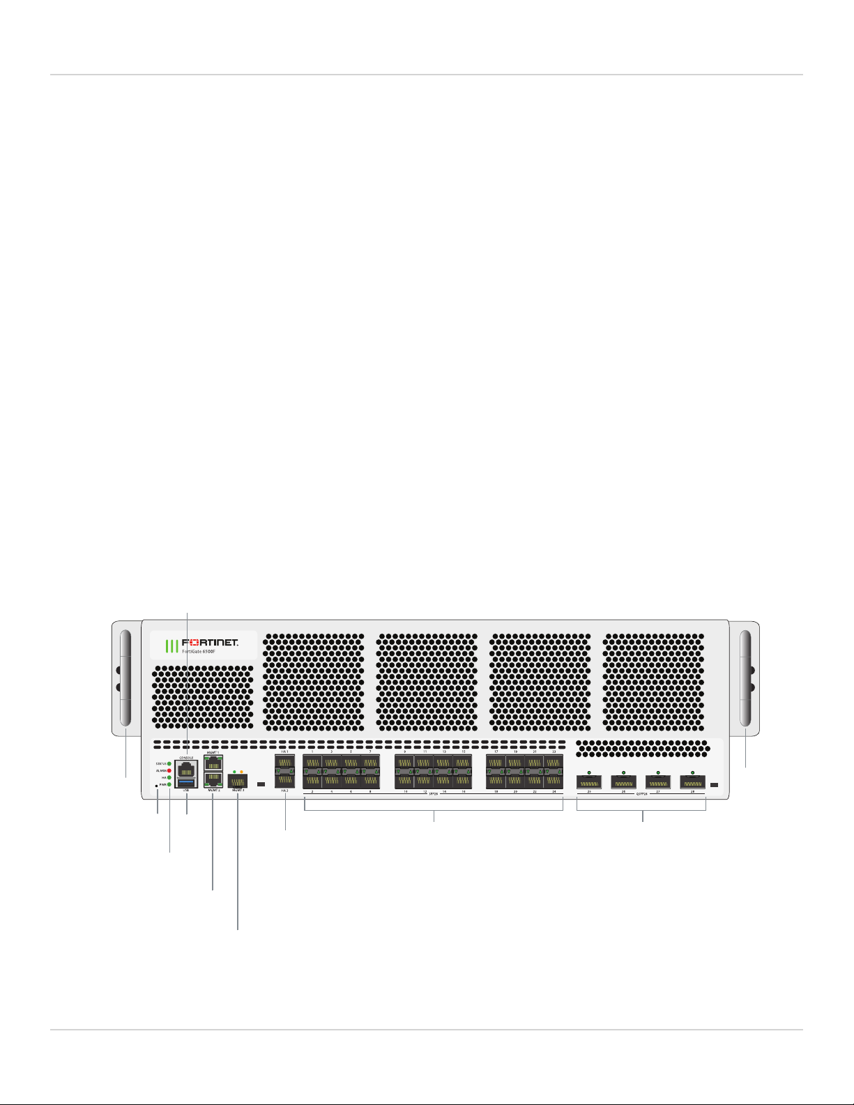
FortiGate-6000F front panel (FortiGate-6500F shown)
Handle
Handle
25 to 28
40/100GigE QSFP28
Data Network Interfaces
HA1 and HA2
10GigE SFP+
HA Heartbeat
Interfaces
1 to 24
1/10/25GigE SFP28
Data Network Interfaces
MGMT1 and MGMT2
10/100/1000BASE-T Copper
Management Interface
MGMT3
1/10GigE SFP+
Management Interface
Status, Alarm,
HA, and Power
LEDs
USB
NMI
Switch
CONSOLE RJ-45
RS-232
Serial Interface
FortiGate-6000F 6.4.2 System Guide 6

FortiGate-6000F hardware description Fortinet Technologies Inc.
Front panel interfaces
All FortiGate-6000F models have the following front panel interfaces:
lTwenty-four 1/10/25GigE SFP28 data network interfaces (1 to 24). The default speed of these interfaces is
10Gbps. These interfaces are divided into the following interface groups: 1 - 4, 5 - 8, 9 - 12, 13 - 16, 17 - 20, and 21
- 24.
lFour 40/100GigE QSFP28 data network interfaces (25 to 28). The default speed of these interfaces is 40Gbps.
lTwo front panel 1/10GigE SFP+ HA interfaces (HA1 and HA2) used for heartbeat, session sync, and management
communication between two and only two FortiGate-6000Fs in an HA cluster. The default speed of these
interfaces is 10Gbps. Operating them at 1Gbps is not recommended. A FortiGate-6000F cluster consists of two
(and only two) FortiGate-6000Fs of the same model. To set up HA, you can use a direct cable connection between
the FortiGate-6000Fs HA1 interfaces and between their HA2 interfaces.
lTwo 10/100/1000BASE-T out of band management Ethernet interfaces (MGMT1 and MGMT2).
lOne front panel 1/10GigE SFP+ out of band management interface (MGMT3).
lOne RJ-45 RS-232 serial console connection.
lOne USB connector.
Interface groups and changing data interface speeds
Depending on the networks that you want to connect your FortiGate-6000F to, you may have to manually change the
data interface speeds. The port1 to port24 data interfaces are divided into the following groups:
lport1 - port4
lport5 - port8
lport9 - port12
lport13 - port16
lport17 - port20
lport21 - port24
All of the interfaces in a group operate at the same speed. Changing the speed of an interface changes the speeds of all
of the interfaces in that group. For example, if you change the speed of port18 from 10Gbps to 25Gbps the speeds of
port17 to port20 are also changed to 25Gbps.
The port25 to port28 interfaces are not part of an interface group. You can set the speed of each of these interfaces
independently of the other three.
Another example, the default speed of the port1 to port24 interfaces is 10Gbps. If you want to install 25GigE
transceivers in port1 to port24 to convert these data interfaces to connect to 25Gbps networks, you can enter the
following from the CLI:
config system interface
edit port1
set speed 25000full
next
edit port5
set speed 25000full
next
edit port9
FortiGate-6000F 6.4.2 System Guide 7

FortiGate-6000F hardware description Fortinet Technologies Inc.
set speed 25000full
next
edit port13
set speed 25000full
next
edit port17
set speed 25000full
next
edit port21
set speed 25000full
end
Front panel LEDs
LED State Description
STATUS
Off The FortiGate-6000F is powered off.
Green The FortiGate-6000F is powered on and operating normally.
Flashing
Green
The FortiGate-6000F is starting up.
ALARM Red Major alarm. One or more analog sensors have surpassed a critical or non-
recoverable (NR) threshold causing an alarm. When a critical threshold
has been reached, it means that a condition has been detected that has
surpassed an operating tolerance. For example, a temperature has
increased above the allowed operating temperature range.
Amber Minor alarm. One or more analog sensors (excluding PSUs) has surpassed
a major or critical (CR)threshold. Any sensor, including sensors on PSUs,
has generated an alert. Sensor alert criteria is defined per sensor. For
analog sensors, alerts usually mean passing an upper critical (UC) or lower
critical (LC) threshold. For other sensors, an alert could mean a flag bit is
indicating an anomaly.
Off No alarms
HA
Off The FortiGate-6000F is operating in normal mode.
Green The FortiGate-6000F is operating in HA mode.
Red The FortiGate-6000F is operating in HA mode and the HA heartbeat
cannot find the other FortiGate-6000F in the HAcluster.
PWR Off The FortiGate-6000F is powered off.
Green The FortiGate-6000F is powered on and operating normally.
1 to 24
Link/Activity Green This interface is connected at 25Gbps /10Gbps /1Gbps with the correct
cable and the attached network device has power.
Flashing
Green
Network traffic on this interface.
FortiGate-6000F 6.4.2 System Guide 8

FortiGate-6000F hardware description Fortinet Technologies Inc.
LED State Description
Off No link is established.
25 to 28
Link/Activity
Green This interface is connected at 100Gbps /40Gbps with the correct cable and
the attached network device has power.
Flashing
Green
Network traffic on this interface.
Off No Link
MGMT1
MGMT2 Link/
Activity (Left
LED)
Green This interface is connected at 1Gbps or 100Mbps with the correct cable
and the attached network device has power.
Flashing
Green
Network traffic on this interface.
Off No link is established.
MGMT1
MGMT2
Speed (Right
LED)
Green This interface is connected at 1Gbps.
Amber This interface is connected at 100Mbps
Off No link is established.
MGMT3 Link/
Activity (Left
LED)
Green This interface is connected at 10Gbps or 1Gbps with the correct cable and
the attached network device has power.
Flashing
Green
Network activity at the interface.
Off No link is established.
MGMT3
(Right LED) Not used.
HA1 HA2
Link/Activity
Green This interface is connected at 10Gbps or 1Gbps with the correct cable and
the attached network device has power
Flashing
Green
Network activity at the interface.
Off No link is established.
Front panel connectors
You connect the FortiGate-6000F to your 25 Gbps or 10 Gbps networks using the 1 to 24 SFP28 front panel interfaces.
You can also connect the FortiGate-6000F to your 100 Gbps or 40 Gbps networks using the 25 to 28 front panel
QSFP28 interfaces. The front panel also includes 10 GigE SPF+ HA heartbeat interfaces (HA1 and HA2), two Ethernet
10/100/1000 copper management interfaces (MGMT1 and MGMT2), a 10 GigE SPF+ management interface
(MGMT3), an RJ-45 RS-232 serial console port, and a USB port. The USB port can be used with any USB key for
backing up and restoring configuration files.
FortiGate-6000F 6.4.2 System Guide 9

FortiGate-6000F hardware description Fortinet Technologies Inc.
Connector Type Speed Protocol Description
1 to 24 SFP28 1/10/25Gbps Ethernet 1/10/25GigE connection using
SFP28 or SPF+ transceivers. For
traffic interfaces.
25 to 28 QSFP28 40/100Gbps Ethernet 40/100GigE connections using
QSFP28 or QSFP+ transceivers. For
traffic interfaces.
MGMT1
MGMT2
RJ-45 10/100/1000Mbps Ethernet 10/100/1000BASE-T copper
connections for out of band
management or system
administration.
MGMT3 SFP+ 1/10Gbps Ethernet 1/10GigE connection using an SFP+
or SFP transceiver. For out of band
management or system
administration.
HA1 HA2 SFP+ 1/10Gbps Ethernet 1/10GigE connection using SFP+ or
SFP transceivers. For HA heartbeat
and synchronization. 1GigE not
recommended.
CONSOLE RJ-45 9600bps
data bits: 8
parity: none
stop bits: 1
flow control: none
RS-232 Serial interface for console access.
USB USB 3.0
Type A
USB 3.0
USB 2.0
Standard USB connector.
Supported transceivers
Transceivers available from Fortinet for the FortiGate-6000F 1 to 24 SFP28 interfaces.
Transceiver Description
FG-TRAN-GC 1GE SFP RJ45 transceiver.
FG-TRAN-SX 1GE SFP transceiver module, short range.
FG-TRAN-LX 1GE SFP transceiver module, long range.
FG-TRAN-SFP+SR 10GE SFP+ transceiver module, short range.
FortiGate-6000F 6.4.2 System Guide 10

FortiGate-6000F hardware description Fortinet Technologies Inc.
Transceiver Description
FG-TRAN-SFP+LR 10GE SFP+ transceiver module, long range.
FG-TRAN-SFP28-SR 25GE SFP28 transceiver module, short range.
FG-TRAN-SFP28-LR 25GE SFP28 transceiver module, long range.
Transceivers available from Fortinet for the FortiGate-6000F 25 to 28 QSP28 interfaces.
Transceiver Description
FG-TRAN-QSFP28-SR4 100GBase-SR4 QSFP28 transceiver, short range.
FG-TRAN-QSFP28-LR4 100GBase-LR4 QSFP28 transceiver, long range.
FG-TRAN-QSFP+SR 40GBase-SR4 QSFP+ transceiver, short range.
FG-TRAN-QSFP+LR 40GBase-LR4 QSFP+ transceiver, long range.
FG-TRAN-QSFP+SR-BIDI 40GBase-LR4 QSFP+ transceiver, short range, bidirectional.
Console port
You can use the USB to RJ-45 RS-232 Console port to connect to the FortiGate-6000F CLI with these settings:
Baud Rate (bps) 9600, Data bits 8, Parity None, Stop bits 1, and Flow Control None
From the Console port, you can connect to the management board (MBD) CLI of the FortiGate-6000F. You can also
press Ctrl-T to switch between the management board CLI and the CLIs of each of the FPCs in your FortiGate-6000F
(the new destination is displayed in the terminal window). The FortiGate-6500F has a management board and 10 FPCs;
11 consoles in total. The FortiGate-6300F has a management board and 6 FPCs; 7 consoles in total.
You should only make configuration changes on the management board CLI; but, you can cycle through individual FPC
consoles to use diagnose,get or execute commands to view information about individual FPCs and for other
operations.
Once the console port is connected to the CLI that you want to use, press Enter to enable the CLI and log in. When your
session is complete you can press Ctrl-T to connect to another CLI.
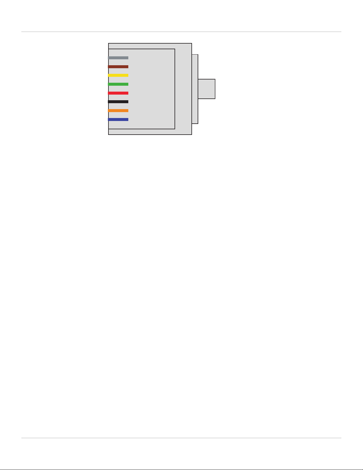
Your FortiGate-6000F package includes a USB to RJ-45 serial cable that you can use to connect a management PC
USB port to the FortiGate-6000F console port.
Fortinet USB to RJ-45 serial cable RJ-45 pinout
RJ-45 Color Function
5 Green Ground
3 Black Rx
6 Yellow Tx
FortiGate-6000F 6.4.2 System Guide 11
FortiGate-6000F hardware description Fortinet Technologies Inc.
1
2
3
4
5
6
7
8
RJ-45
Ground (green)
Rx (black)
Tx (yellow)
Connecting to the CLI of an individual FPC
Use the following steps to connect to the CLI of the FPC in slot 4: (FPC04)
1. Connect the console cable supplied with your FortiGate-6000F to the console port and to your PC USB port.
2. Start a terminal emulation program on the PC. Use these settings:
Baud Rate (bps) 9600, Data bits 8, Parity None, Stop bits 1, and Flow Control None.
3. Press Ctrl-T to enter console switch mode.
4. Repeat pressing Ctrl-T until you have connected to FPC04. Example prompt:
<Switching to Console: FPC04 (9600)>
5. Login with an administrator name and password.
6. When your session is complete, enter the exit command to log out.
NMI switch and NMI reset commands
When working with Fortinet Support to troubleshoot problems with your FortiGate-6000F you can use the front panel
non-maskable interrupt (NMI) switch to assist with troubleshooting. Pressing this switch causes the software to dump
management board registers/backtraces to the console. After the data is dumped the management board reboots.
While the management board is rebooting, traffic is temporarily blocked. The management board should restart
normally and traffic can resume once the management board is up and running.
You can use the following command to dump registers/backtraces of one or more FPCs to the console. After the data is
dumped, the FPCs reboot. While the FPCs are rebooting, traffic is distributed to the remaining FPCs. The FPCs should
restart normally and traffic can resume once they are up and running.
execute load-balance slot nmi-reset <slot-number(s)>
Where <slot-number(s)> can be one or more FPCslot numbers or slot number ranges with no space and
separated by commas. For example:
execute load-balance slot nmi-reset 1,3-4
FortiGate-6000F 6.4.2 System Guide 12
FortiGate-6000F hardware description Fortinet Technologies Inc.
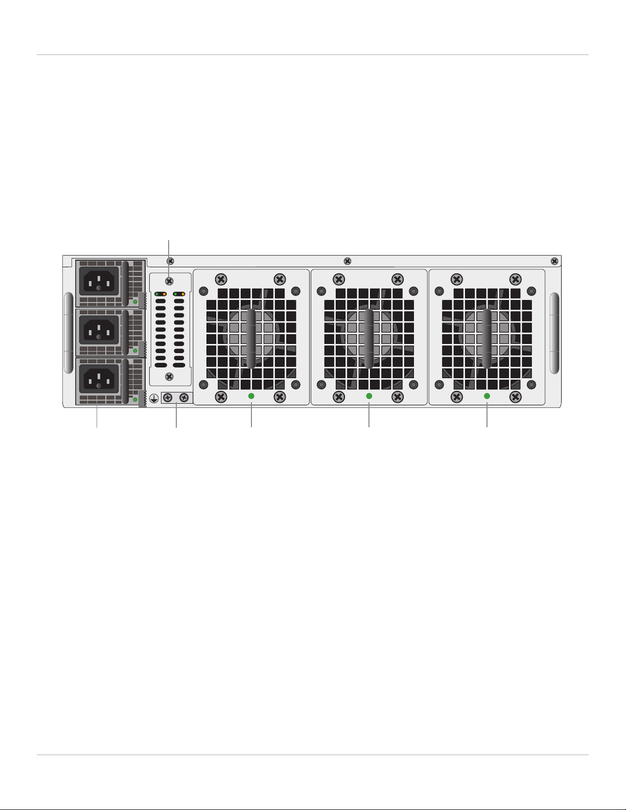
FortiGate-6000F back panel
The FortiGate-6000F back panel includes three hot swappable cooling fan trays and three hot swappable redundant AC
power supply units (PSUs). For more information on power connections and redundant power, see FortiGate-6000F AC
power supply units (PSUs) on page 17.
The back panel also includes the FortiGate-6000F ground connector that must be connected to ground.
FortiGate-6000F back panel (FortiGate-6501F AC model shown)
FAN 1
PSU1 PSU3
SSD1 SSD2 FAN 2FAN 3
Fan Tray 3Fan Tray 2Fan Tray 1Power
Supplies
1, 2, and 3
SSD Log Disks
(6501F and 6301F)
Ground
Connector
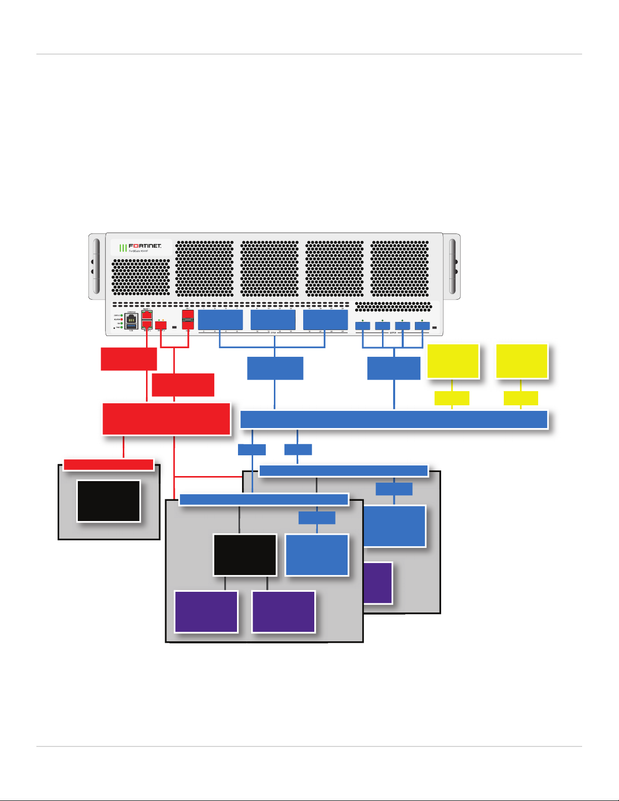
FortiGate-6000F schematic
FortiGate-6000F hardware includes a data plane and a management plane. The data plane processes customer
network data. The management plane handles management functions such as administrator logins, configuration and
session synchronization, SNMP,and other monitoring, HA heartbeat communication, and remote and (if supported)
local disk logging. Separating these two planes means that resources used for data processing are not compromised by
management activities.
In the data plane, two DP3 load balancers use session-aware load balancing to distribute sessions from the front panel
interfaces (port1 to 28) to Fortinet Processor Cards (FPCs). The DP3 processors communicate with the FPCs across the
3.2Tbps integrated switch fabric. Each FPC processes sessions load balanced to it. The FPCs send outgoing sessions
back to the integrated switch fabric and then out the network interfaces to their destinations.
The NP6 processor in each FPC enhances network performance with fastpath acceleration that offloads communication
sessions from the FPC CPU. The NP6 processor can also handle some CPU intensive tasks, like IPsec VPN
encryption/decryption.
FortiGate-6000F 6.4.2 System Guide 13
FortiGate-6000F hardware description Fortinet Technologies Inc.
The CP9 processors in each FPC accelerate many common resource intensive security related processes such as SSL
VPN, Antivirus, Application Control, and IPS.
The management plane includes the management board, base backplane, management interfaces, and HA heartbeat
interfaces. Configuration and session synchronization between FPCs in a FortiGate-6000F occurs over the base
backplane. In an HA configuration, configuration and session synchronization between the FortiGate-6000Fs in the
cluster takes place over the HA1 and HA2 interfaces. Administrator logins, SNMP monitoring, remote logging to one or
more FortiAnalyzers or syslog servers, and other management functions use the MGMT1, MGMT2, and MGMT3
interfaces. You can use the 10Gbps MGMT3 interface for additional bandwidth that might be useful for high bandwidth
activities such as remote logging.
FortiGate-6000 schematic
CPU
1 - 24
24x10/25GE
12xKR
25 - 28
4x40/100GE
DP3
12xKR
DP3
6xKR
FortiGate-6500 = 10x FPCs
FortiGate-6300 = 6x FPCs
CPU
CP9 CP9
Fortinet Processor Card (FPC)
NP6
4x XAUI
MGMT3 HA1
HA2 3x10G
6xKR
CPU
CP9 CP9
Fortinet Processor Card (FPC)
NP6
4x XAUI
Integrated Switch Fabric (3.2 Tbps) (Data Plane)
MGMT1 & 2
2x 1G
6
Base Backplane
(Management Plane)
Management Board
FortiGate-6000F 6.4.2 System Guide 14

FortiGate-6000F hardware description Fortinet Technologies Inc.
FortiGate-6000F hardware information
This section introduces FortiGate-6000F hardware components and accessories.
Shipping components
The FortiGate-6000F ships pre-assembled with the following components:
lThe 3U FortiGate-6000F.
lThe AC version of the FortiGate-6000F includes three AC Power Supply Units (PSUs) installed in the back panel.
lThe AC version of the FortiGate-6000F includes three power cords with C15 power connectors.
lThree cooling fan trays installed in the back panel.
lOne set of two sliding rails for 4-post rack mounting.
lSix rubber feet.
lOne USB to RJ-45 RS-232 console cable.
lOne RJ-45 Ethernet cable.
lTwo FG-TRAN-SFP+SR transceivers.
Optional accessories and replacement parts
The following optional accessories can be ordered separately:
SKU Description
FG-6000F-FAN FortiGate-6000F fan tray.
SP-FG4000F-PS 2000W AC PSU when connected to high line AC power (200VAC or higher). 1500W AC if
connected to low-line AC (120VAC or below).
FG-7040E-PS-AC 1500W AC PSU. (FortiGate-6000F Generation 1)
You can also order the following:
lTransceivers
Physical description of the FortiGate-6000F
The FortiGate-6000F is a 3U appliance that can be installed in a standard 19-inch rack. The following table describes
the physical characteristics of the FortiGate-6000F chassis.
Form factor 3RU
Dimensions (H x W x D) 5.20 x 17.20 x 26.18 in (132 x 437 x 665 mm)
Rack mount type Sliding rail
FortiGate-6300F and 6301F weight 67.68 lbs 30.7 kg
FortiGate-6000F 6.4.2 System Guide 15

FortiGate-6000F hardware description Fortinet Technologies Inc.
FortiGate-6500F and 6501F weight 78.26 lbs 35.5 kg
Operating temperature 32 to 104°F (0 to 40°C)
Storage temperature -31 to 158°F (-35 to 70°C)
Relative humidity 20% to 90% non-condensing
Average noise level 57.43 dbA
Input voltage range 100 to 240 VAC (50 to 60 Hz)
Supplied power supply units (PSUs)
Max power consumption 1568W
Average power consumption 1328W
Max current (AC) 30A@100VAC, 20A@240VAC
Heat dissipation 5350 BTU/hr
Joules/hr 5645 KJ/hr
FortiGate-6000F hardware generations
Two generations of FortiGate-6000F hardware are now available. Both generations support the same software
features. Generation 2 has two hardware improvements:
lThe FPCs include more memory.
lWhen connected to high-line AC power, generation 2 FortiGate-6000F models provide 1+1 PSU redundancy. When
connected to high-line AC power, each PSU provides 2000W, which is enough power to run the entire system
including all FPCs.
For more information on FortiGate-6000F generation 1 and generation 2, including supported firmware versions and
how to determine the generation of your FortiGate-6000F hardware, see the Fortinet Knowledge base article: Technical
Tip: Information on FortiGate-6000F series Gen1 and Gen2.
For more information on generation 1 and generation 2 AC PSUs, see FortiGate-6000F AC power supply units (PSUs)
on page 17.
Cooling fan trays
The FortiGate-6000F contains three hot swappable cooling fan trays installed in the back of the appliance. When the
fan LED is green the fan tray is operating normally. If a fan tray LED turns red or goes off the fan tray should be
replaced.
FortiGate-6000F 6.4.2 System Guide 16

FortiGate-6000F hardware description Fortinet Technologies Inc.
Cooling Fan Tray
Retention
Screw
Fan
LED
Handle
Retention
Screw
Retention
Screw
Retention
Screw
Fan
LED
Fan trays are hot swappable. You can replace a failed fan tray while the FortiGate-6000F is operating. To replace a fan
tray, unscrew the four retention screws and use the handle to pull the fan tray out of the chassis. Install the new fan tray
by sliding it into place. As you slide the new fan into place it will power up. Tighten the retention screws.
The other fan trays will continue to operate and cool the chassis as a fan tray is being removed and replaced. However
an open fan tray slot will result in less air flow through the appliance so do not delay installing the replacement fan tray.
The FortiGate-6000F monitors the internal temperature of the appliance and adjusts the operating speed of the cooling
fans as required. When the device is first powered on all cooling fans run at full speed. Once the system is up and
running, the fan speeds are reduced to maintain an optimum temperature in the appliance.
During normal operation, all fan trays are active. If cooling requirements increase, the fan speed will increase.
FortiGate-6000F AC power supply units (PSUs)
The FortiGate-6000F back panel includes three hot swappable redundant AC PSUs (PSU1, PSU2, and PSU3). Two
generations of FortiGate-6000F models have been released. Generation 1 and generation 2 have different AC PSUs:
lGeneration 2 FortiGate-6000F PSUs can be connected to high-line AC power (200VAC or higher) and each PSU
provides 2000W AC. A generation 2 FortiGate-6000F with two high line power feeds connected to PSU1 and PSU2
is a fully 1+1 redundant solution because a single PSU can fully power a FortiGate-6000F.
lGeneration 1 FortiGate-6000F PSUs can be connected to low line AC power (120VAC or below) and each PSU
provides 1500W AC. Requires at least 2 PSUs to be connected to power. Connecting a third PSU provides 2+1
redundancy. If only one PSUis operating, some FPCs will be shut down and performance will be reduced.
lYou can also connect generation 2 FortiGate-6000F PSUs to low-line AC power (120VAC or below) and each PSU
provides 1500W AC. Requires at least 2 PSUs to be connected to power. Connecting a third PSU provides 2+1
redundancy. If only one PSUis operating, some FPCs will be shut down and performance will be reduced.
Use a supplied C15 power cable to connect power to each PSU C16 power connector. C15/C16 power connectors are
used for high temperature environments and are rated up to 120°C.
FortiGate-6000F 6.4.2 System Guide 17

FortiGate-6000F hardware description Fortinet Technologies Inc.
For more information on FortiGate-6000F generation 1 and generation 2, including supported firmware versions and
how to determine the generation of your FortiGate-6000F hardware, see the Fortinet Knowledge base article: Technical
Tip: Information on FortiGate-6000F series Gen1 and Gen2.
Generation 1 AC PSU showing C16 power connector
Latch
PSU
LED
C16
Power
Connector
Generation 2 AC PSU showing C16 power connector
Latch
PSU
LED
C16
Power
Connector
Connecting generation 2 FortiGate-6000F PSUs to high line AC power
If you connect a generation 2 FortiGate-6000F to high-line AC power, each PSU provides 2000W AC, which is all the
power required by the FortiGate-6000F. Only two PSUs (PSU1 and PSU2) each connected to separate power feeds, are
required for full 1+1 power redundancy. PSU3 may also be connected if you have three separate power feeds and
provides 1+1+1 redundancy. To maintain redundancy, you should replace any failed PSUs.
See FortiGate-6000F back panel on page 13 for locations of the PSUs.
Recommended fully redundant configuration when connected to high-line AC power:
lTwo FortiGate-6000Fs in a High Availability (HA) configuration connected to two power feeds.
lOn both FortiGate-6000Fs, connect PSU1and PSU2 to different power feeds.
FortiGate-6000F 6.4.2 System Guide 18

FortiGate-6000F hardware description Fortinet Technologies Inc.
Connecting generation 1 or 2 FortiGate-6000F PSUs to low line AC power
If you connect a generation 1 FortiGate-6000F or a generation 2 FortiGate-6000F PSU to low line AC power, each PSU
provides 1500W ACand at least two PSUs (PSU1 and PSU2) must be connected to power. PSU3 is a backup PSU and
provides 2+1 redundancy. All PSUs should be connected to AC power.
See FortiGate-6000F back panel on page 13 for locations of the PSUs.
Recommended FortiGate-6000F low line AC power fully redundant configuration:
lTwo FortiGate-6000Fs (Unit 1 and Unit 2) in a High Availability (HA) configuration with two power feeds (Feed A
and Feed B).
lConnect PSU1 and PSU2 of Unit 1 to Feed A. Connect PSU3 of Unit 1 to Feed B.
lConnect PSU1 and PSU2 of Unit 2 to Feed B. Connect PSU3 of Unit 2 to Feed A.
For normal operation of a FortiGate-6000F connected to low line AC power, at least 2 PSUs must be operating and
connected to power. If two PSUs fail and only one PSU is operating, the FortiGate-6000F will continue to operate but
only four FPCs will be running, the remaining FPCs are shut down. This means the performance of the FortiGate-6000F
is reduced until at least two PSUs are connected.
If only one PSU is operating, the FortiGate-6000F shuts down the FPCs starting with the FPC
with the highest slot number, until only four FPCs are running. Usually this results in the FPCs
in slots 1 to 4 running if there is only one PSU connected.
If one of the FPCs in slot 1 to 4 has previously shut down, the FortiGate-6000F keeps the four
operational FPCs in the lowest slot numbers running. For example, if the FPCin slot 2 has
previously shut down, if only one PSU is operating, the FPCs in slots 1, 3, 4, and 5 continue
running.
The FortiGate-6000F also keeps the primary FPC running. Usually the FPC in slot 1 is the
primary FPC, so if only one PSU is operating, the FPCs in slots 1 to 4 continue running.
However, if the FPC in another slot has become the primary FPC, then this FPC as well as the
three remaining FPCs with the lowest slot numbers will continue running. For example, if the
FPCin slot 6 has become the primary FPC, then when only one PSU is operating, the FPCs in
slots 1, 2, 3, and 6 continue running.
AC PSU LED states
The PSU LED indicates whether the PSUis operating correctly and connected to power.
State Description
Off AC power not connected. If this LEDis not lit, check to make sure the PSU is
connected to a power feed. If the power feed is good then the PSU has failed and
should be replaced.
Flashing green The PSUis in standby mode, not supplying power to the chassis.
Green Normal Operation with AC power connected.
Amber Input voltage outside of normal operating range, PSU fan not operating, or output
voltage outside of normal operating range.
FortiGate-6000F 6.4.2 System Guide 19
FortiGate-6000F hardware description Fortinet Technologies Inc.
State Description
Flashing amber Warning that power input or output is close to outside of normal operating range.
PSU should be replaced.
Connecting FortiGate-6000F PSUs to AC power
Use the following steps to connect a FortiGate-6000F PSU to AC power after connecting the chassis to ground.
1. Use the supplied C15 Power cables to connect each PSU C16 power connector to a separate surge protected
power supply.
You can install power cord clamps into the back of the chassis beside each PSU. Install the clamps by inserting
them into the holes adjacent each supply at the back of the chassis. Use the clamps to secure the AC power cords
so they are not accidentally disconnected.
2. As the FortiGate-6000F powers up, the status LED flashes green.
Once the FortiGate-6000F has started up and is operating correctly, the front and back panel LEDs should indicate
normal operation (see Confirming startup status on page 31).
Hot swapping an AC PSU
Follow these steps to safely hot swap an AC PSU.
You can hot swap a PSU without affecting performance or interrupting traffic as long as one
PSU remains connected to power at all times.
1. Attach an ESD wrist strap to your wrist and to an ESD socket or to a bare metal surface on the chassis or frame.
2. Turn off the power being supplied to the PSU and disconnect the power cord.
3. Press the latch towards the handle until the PSU is detached then pull it out of the FortiGate-6000F.
4. Insert a replacement PSU into the FortiGate-6000F and slide it in until it locks into place.
5. Use a supplied C15 power cable to connect power to the PSU C16 power connector.
6. Turn on power to the PSU.
7. Verify that the PSU status LED is solid green meaning that the PSU is powered up and operating normally.
Connecting the FortiGate-6000F to ground
The FortiGate-6000F appliance includes a ground terminal on the FortiGate-6000F back panel. The ground terminal
provides two connectors to be used with a double-holed lug such as Thomas & Betts PN 54850BE. This connector must
be connected to a local ground connection.
You need the following equipment to connect the FortiGate-6000F to ground:
lAn electrostatic discharge (ESD) preventive wrist strap with connection cord.
lOne green 6 AWG stranded wire with listed closed loop double-hole lug suitable for minimum 6 AWG copper wire,
such as Thomas & Betts PN 54850BE.
FortiGate-6000F 6.4.2 System Guide 20
This manual suits for next models
4
Table of contents
Other Fortinet Power Supply manuals


