SERVICE
SAFETY
PRECAUTIONS
1.
Replacing
the
fuses
CAUTION:
FOR
CONTINUED
PROTECTION
AGAINST
THE
RISK
OF
FIRE
REPLACE
ONLY
WITH
SAME
TYPE
OF
FUSE.
Reference
No.
Part
No.
Description
F901*AH
252163
4A-125V
UL/T-237
Time
lag
F901*B1,
B,
C
252074
T2A
L/250V
SE-EAK
Time
lag
NOTE:
<*AH>
:
U.S.A.
CANADIAN
MODEL
ONLY.
<*B1>
:
AUSTRALIAN
MODEL
ONLY.
<*C>
:
EUROPEAN
MODEL
ONLY.
<*B>
:
U.K.
MODEL
ONLY.
2.
SAFETY
CHECK
OUT
(Only
U.S.A.
model)
Before
returning
the
product
to
the
customer,
make
leakage
current
or
resistance
measurements
to
determine
that
exposed
parts
are
acceptably
insulated
from
the
supply
circuit.
Parts
marked
with
the
symbol
A
are
critical
with
regard
to
the
risk
of
fire
and
electric
shock.
Replace
only
with
parts
recommended
by
the
manufacturer.
CONTENTS
DESCRIPTION
PAGE
SERVICE
SAFETY
PRECAUTIONS
--~-~-->-=77>7777>7777-
2
FRONT
PANEL
/
REAR
PANEL
VIEW
~---~--7-7-~777-77>-~
3
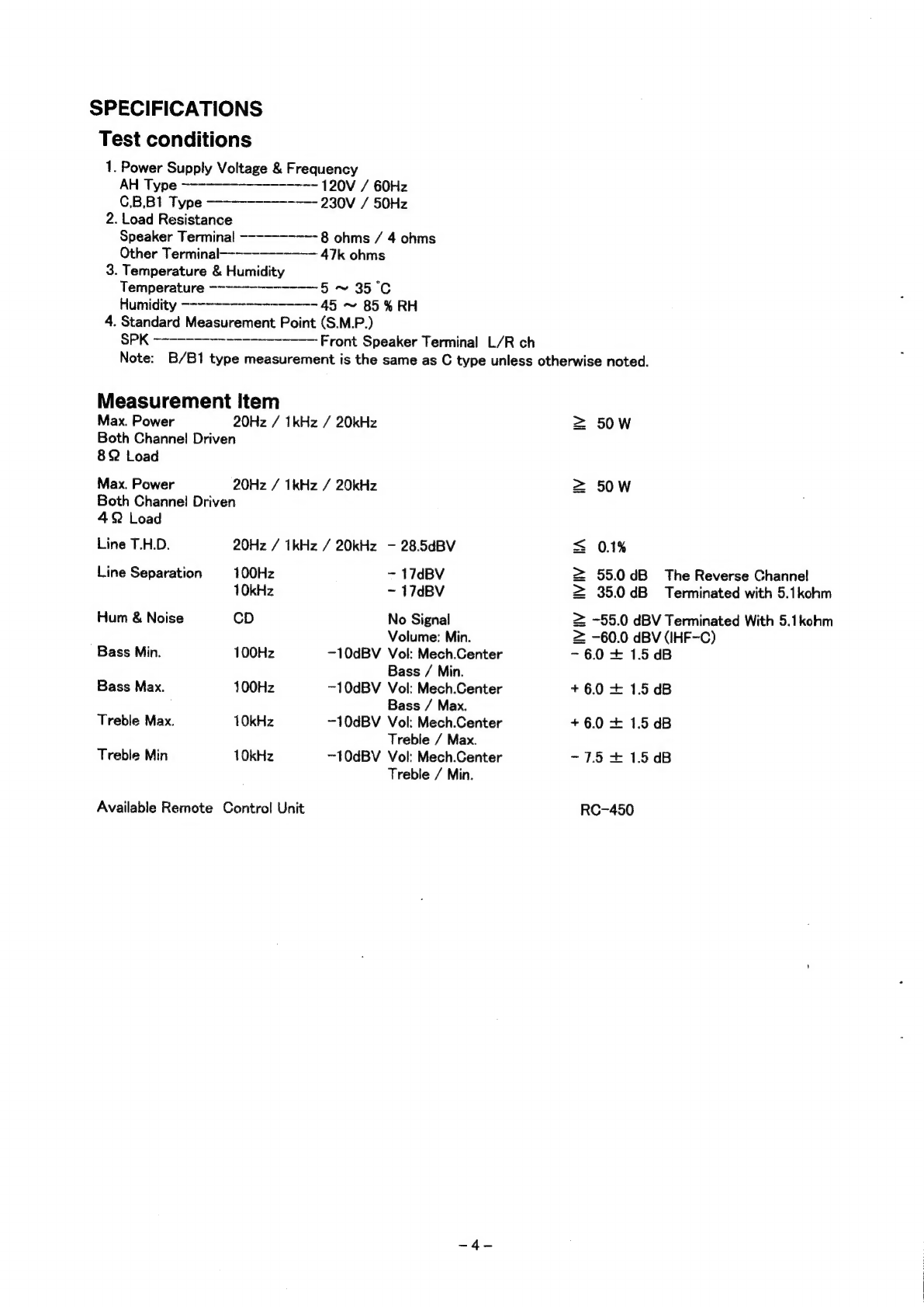
SPECIFICATIONS...
227s
sr
ecne
ee
eseneseee
caeaaoeeee
4
ALIGNMENT
PROCEDURE
9
~-~~-~--~--7-7---"-"--------
5
WIRING
DIAGRAM
--~---------------~-----------------
6
BLOCK
DIAGRAM
-------------------------+--+--------
7
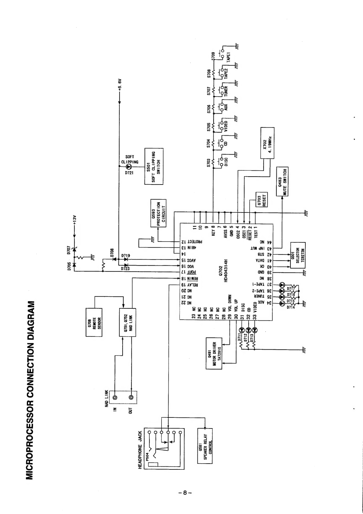
MICROPROCESSOR
CONNECTION
DIAGRAM
------------
8
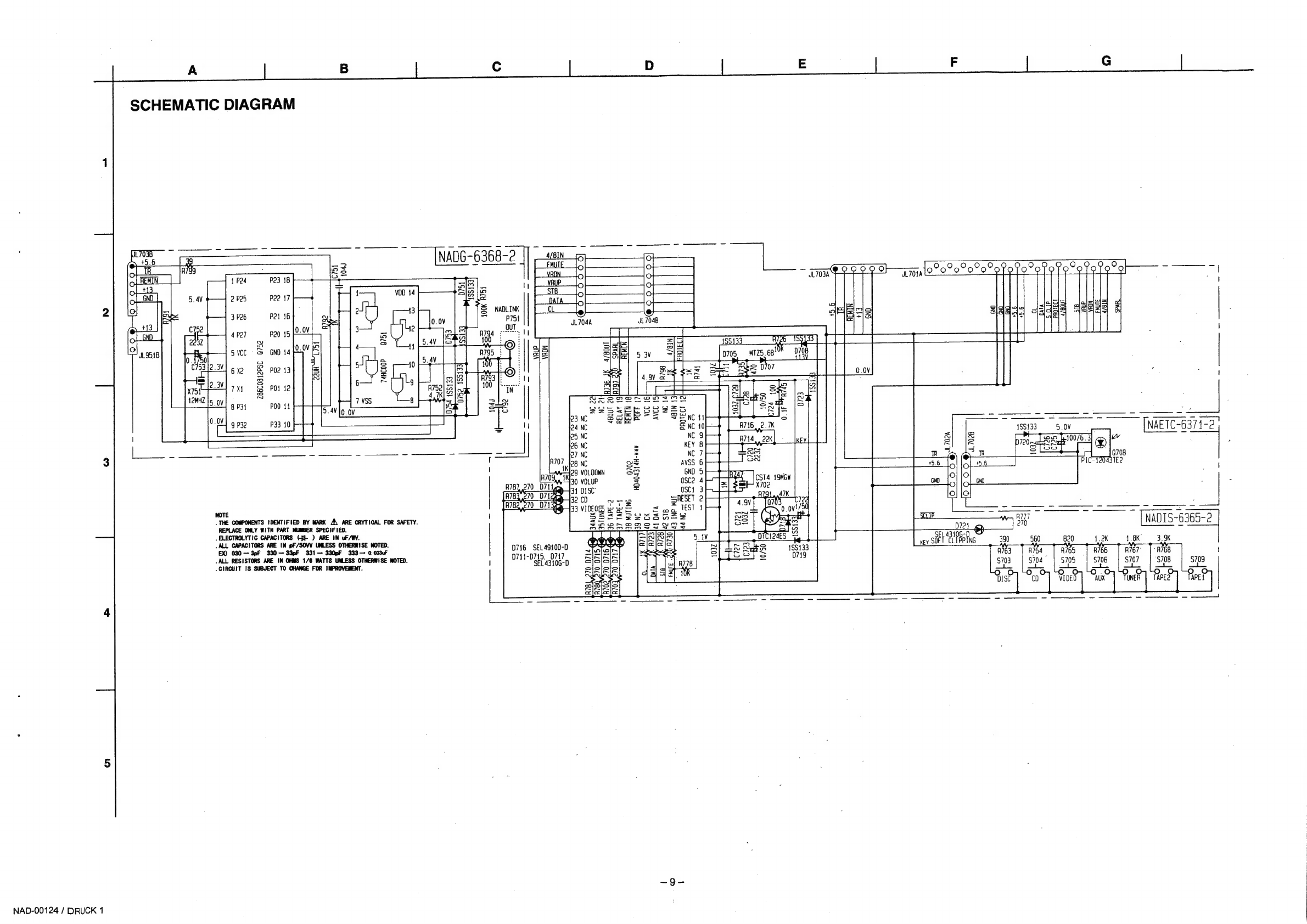
SCHEMATIC
DIAGRAM
—------------------------------
9-10
PCBLAYOUT
9
~----==------------------22+2-2-----
11-12
IC
BLOCK
DIAGRAM)
~=-~---~----------------------:
13
EXPLODED:
VIEW)
<=<252-ese-so-cesaecsosuehsetetastess
14
EXPLODED
VIEW
PARTS
LIST
------------------------
15-16
ELECTRICAL
PARTS
LIST
------------------------------
17-18
PACKING
DIAGRAM
/
PARTS
LIST
----------------------
19