ALIGNMENT PROCEDURE (T977)
A. THERMALSENSE ADJUSTMENT
This adjustment should be always done when the T977 is cool condition. (That means the
temperature inside the unitshouldbe almost same as theambient temperature.
Connector P208B thatconnectsthe transformerand power board should be removed to
avoid that the Idling current heats up the unit excessively) At ambient temperature of 25 C
degrees and when the unit is just turned on(still in cool condition), adjust the pot
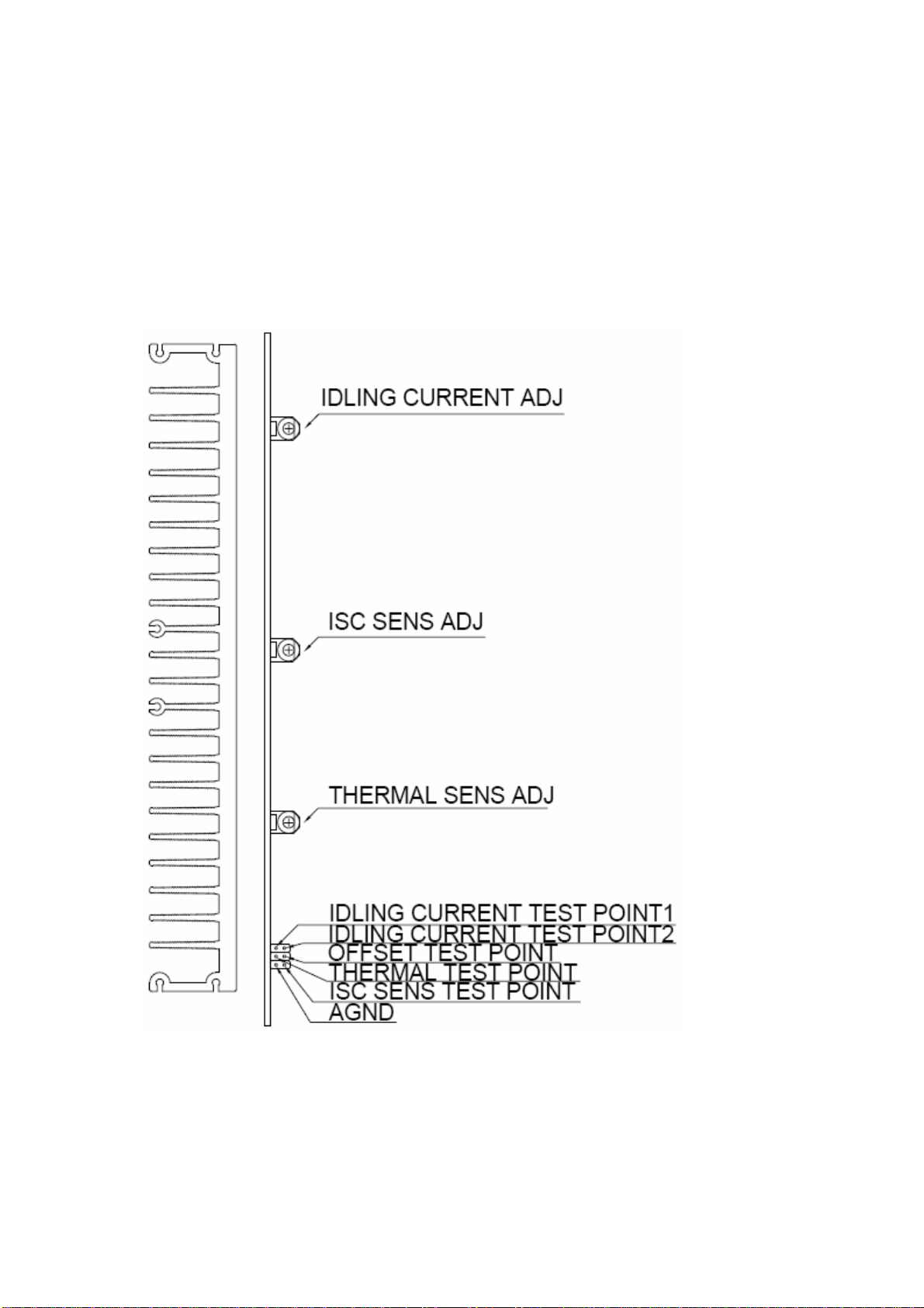
RV103(as marked as“Thermal Sense ADJ” in below drawing) for avoltage between the
THERMALTESTPOINT and AGND tobe 750mV+/-10mV.If the ambient temperature is
different, the voltage setting should be changed by20mV per degree difference. So at
20C degrees, the voltage should be 850mV+/-10mV;and at30C degrees, the voltage
should be 650mV+/-10mV, etc.
B. DC OFFSET VOLTAGE
The DC OFFSETbetween OFFSETTest PointandAGND must be within 0+/-3mV.If it’s
found to be out of this range, change theTL084BCD to one selected for lowoffset voltage
to meet the requirement.
C. IDLING CURRENT
Theidling current in the output stage of the poweramp should be set to 40mA+/-10mA
per pnp-npn transistor pair( This means the mid point voltage is 17.6mV with down limit of
13.2mV and up limit of22mV). The alignment procedure is: At first, adjust RV102 (Marked
as “Idling Current ADJ” in thedrawing below) for avoltage of 17.6mV +/- 1mV between
Test point 1and2. Then preheat the unit for 5minutes, let idling current settled and then
readjust to 17.6mV+/- 1mV.
Pls note:
1. The idling current must be adjusted when all modules are assembled intothe unit.
2. Though the idlingcurrentis set as 17.6mV+/-1mVduring theadjustment,duetothe
influence ofvaried ambienttemperatureand mains voltage etc.,the idlingcurrent willdrift
aftersometime.Duringthe normal checking of idlingcurrent inthe servicefield, it’s
acceptable as long as the voltage is inthe range of 13.2mV—22.0mV.
D. ISC SENSITIVITY
TheISC sensing voltage can allow 0mV+/-50mV.But, for thealignment process in our
factory,we tighten the limit to 0mV+/-10mV.That isto adjust Pot RV104(as marked as
“ISC SENSE ADJ” in the below drawing) to get a voltage between the “ISC SENSETEST
POINT” and AGND to be 0mV+/-10mV.
(Pls note the ISC should be adjusted when all modules are plugged in.It’snot possible to get
0mV+/-10mVif any of the modules are removed.)
E. Fan Cut Off PointAdjustment
Check the Fansensevoltage first. Turn Pot RV201 to the endclockwise and confirmTP2
of J201 is in negative voltage. Run the unit toheat it up and drive the fan to start turning,
- 5 -