Nagasoft NSCaster User manual

1.1 LIST ACCESSORIES.........................................................................................................................................................1
1.2 DEVICE PARAMETERS...................................................................................................................................................1
1.3 MODEL............................................................................................................................................................................1
1.4 INTERFACE DIAGRAM ...................................................................................................................................................2
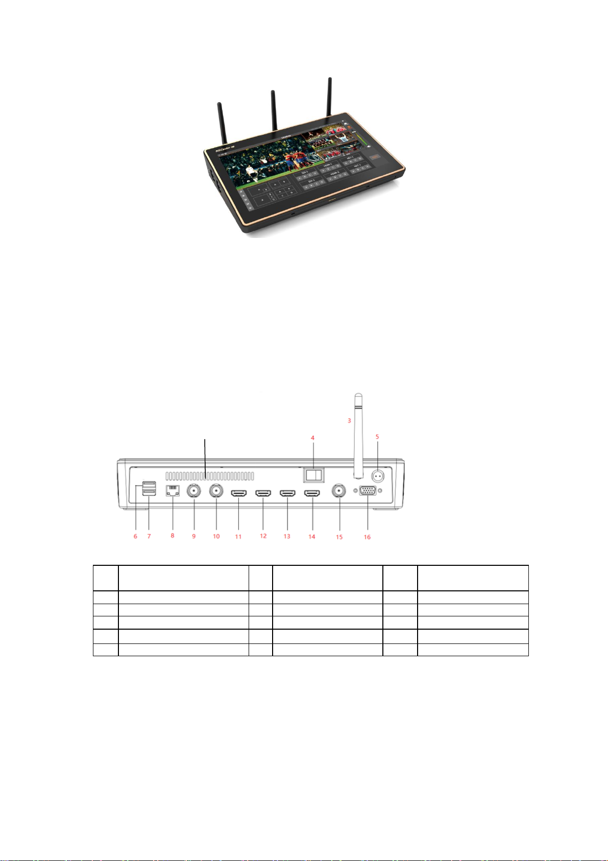
1.4.1 Back Interface.......................................................................................................................................................2
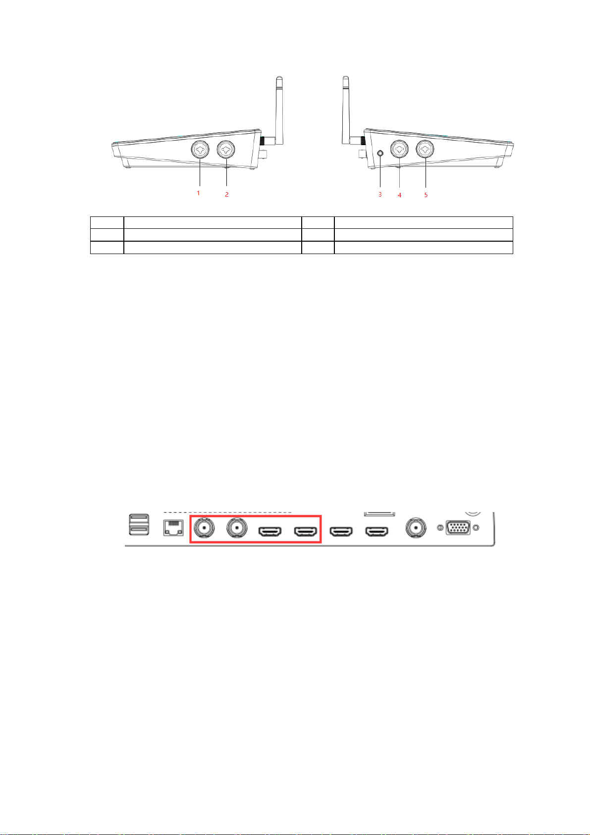
1.4.2 Side Interface........................................................................................................................................................2
1.4.3 Bottom interface...................................................................................................................................................3
2 INSTALLATION AND COMMISSIONING..............................................................................................................3
3 SOFTWARE FEATURES ................................................................................................................................................6
3.1 NSCASTER MAIN INTERFACE......................................................................................................................................6
3.1.1 PGM .......................................................................................................................................................................7
3.1.2 SDI Channel..........................................................................................................................................................7
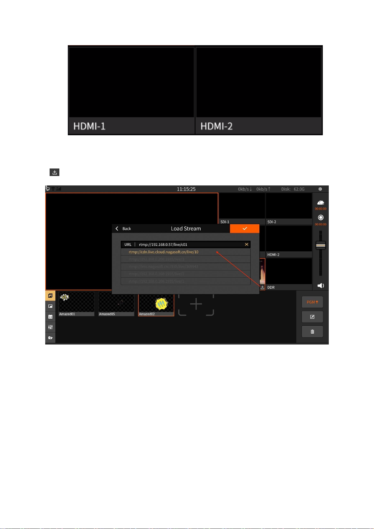
3.1.3 HDMI Channel.....................................................................................................................................................7
3.1.4 NET Channel.........................................................................................................................................................8
3.1.5 DDR Channel........................................................................................................................................................8
3.1.6 Image Overlay ......................................................................................................................................................9
3.1.7 PIP (Picture in Picture)....................................................................................................................................11
3.1.8 Scoreboard..........................................................................................................................................................12
3.1.9 Audio Mixer.........................................................................................................................................................13
3.2 NSCASTER SETTINGSINTERFACE.............................................................................................................................14
3.2.1 Channel Recording............................................................................................................................................15
3.2.2 Recording............................................................................................................................................................15
3.2.3 Streaming.............................................................................................................................................................16
3.2.4 Clock.....................................................................................................................................................................19
3.2.5 Network................................................................................................................................................................19
3.2.6 File Transfer .......................................................................................................................................................20
3.2.7 General Settings.................................................................................................................................................22
3.2.8 About....................................................................................................................................................................23
4 QUESTIONS AND ANSWERS.....................................................................................................................................23

1
1Hardware Specification
1.1 List Accessories
1.2 Device Parameters
Device Item Name
Description
Chassis
Portable case, built-in with 11.6-inch high-definition touch screen
Dimensions
294mm*193mm*54mm (W x H x D)
Weight
1.25KG
Powered by
100~240V AC
Transport box
Carton
Operating temperature
-10-50℃
Storage temperature
-20-70℃
Operating humidity
10~90% nocondensation
Impact resistance
15g
Vibration resistance
10-100Hz 1.25g
Altitude
Below 4000 meters
1.3 Model
Name/Model
Package
Specification
Number
of Pieces
Actual
Quantit
y
Remarks
Main device
Carton
packaging
NSCaster
1
1
Power supply and
power cord
Carton
packaging
Standard
1
1
WIFI antenna
Carton
packaging
Standard
1
1
User manual
Carton
packaging
Nagasoft Custom
1
1
Warranty card
certificate
Carton
packaging
Nagasoft Custom
1
1

2
Standard Version
1.4 Interface Diagram
1.4.1 Back Interface
1) The back interface of the standard version is shown below:
1
/
7
USB3.0
13
HDMI Display
interface
2
/
8
Gigabit Ethernet port
14
HDMI PGM Output
3
WIFI antenna
9
SDI-1 Input
15
SDI PGM Output
4
Switch
10
SDI-2 Input
16
TALLY
5
Power supply(DC19V)
11
HDMI-1 Input
17
Cooling port
6
USB2.0
12
HDMI-2 Input
1.4.2 Side Interface
The side interface of the standard version is shown below:
17

3
1
XLR/TRS balanced input L
4
XLR/TRS balanced output L
2
XLR/TRS balanced input R
5
XLR/TRSbalanced output R
3
3.5mmmonitor
1.4.3 Bottominterface
1) The bottom interface of the standard version is shown:
2Installation and Commissioning
1) Open the box, then take out the power cord and NSCaster device. After that, lay the device on a
stable surface.
2) Connect the power cord and the corresponding WIFI . Then, use a network cable to connect to the
RJ45 Gigabit Ethernet port.
3) Connect the output of the AV equipment (such as camera) to the NSCaster device input interface.
The SDI/HDMI camera is connected to the SDI/HDMI input via SDI/HDMI cable as shown
below:
The mixer is connected to the TRS MIC input port through theTRS cable,or the XLR cable is
connected to the XLR input as shown below:

4
4) In order to connect the NSCaster device output port to the monitor, it has divided into following
categories:
The SDI monitor is connected to the SDI output via an SDIcable.
The HDMI monitor is connected to the HDMI output via HDMI cable.
5) Connect thesound output of the NSCaster device to an external device or monitor.
Connect to the TRS MIC output through the TRS cable, or connect to the XLR output
interface through the XLR cable as shown below:
Connect to the call output interface through a 3.5mm audio cable as shown below:

5
6) To start the NSCaster device, just press the power button on the NSCaster device as shown below:
7) After the NSCaster device is started, it will enter the main interface of NSCaster as shown in the
following figure:
8) The SDI video signal and HDMI video signal are directly loaded into the main interface.
9) To load NET signal,select " " in the NET channel and enter the stream in the pop-up stream
edit box.
10) To load DDR signal, select the DDR button in the DDR alternate video window, and select one of
the video sources, then click Play to load the video into the DDR channel.
11) Select the output channel and press therecord button " " to start record.
12) To start switching, tap once on the channel you want (SDI-1,SDI-2,HDMI-1,HDMI-2,NET,DDR)
and it will switch to PGM.

6
13) Start uploading the picture on PGM as shown below:
14) Press again the record button to stop recording.
15) Check whether all the recording files are normal. The recording file is saved in the “Recording”
folder which located at the “File Transfer” interface.
16) Press the Power On/Off button to turn off the NSCaster device.
17) Turn off the power switch of the device, unplug the power supply, and unplug all input and output
video cables and antennas, then keep the NSCaster device properly.
3Software Features
3.1 NSCaster Main Interface
NO
Name
NO
Name
1
PGM
9
Streaming control
2
SDI input channel
10
Recording control
3
HDMI input channel
11
Tuning control for total mix output
4
NET input channel
12
Image overlay
5
DDR display channel
13
PIP (Picture in picture)

7
6
Network status display
14
Scoreboard
7
Resource usage monitoring status
15
Audio mixer
8
Settings button
16
DDR
3.1.1 PGM
PGM channel: Monitor the screen that being broadcast. Single tap on the channel you want (SDI-
1,SDI-2,HDMI-1,HDMI-2,NET,DDR) and it will switch to PGM as shown below:
3.1.2 SDI Channel
SDI-1 and SDI-2can be connected to SDI cameras or other devices as shown below:
3.1.3 HDMI Channel
HDMI-1 and HDMI-2 can beconnected to HDMI cameras or other devices as shown below:

8
3.1.4 NET Channel
The NET channel is used to load network streams and the supported formats are: rtmp/rtsp. Click
“ ” to enter the network stream editing interface as shown below:
3.1.5 DDR Channel
The DDR channel is used to load video footage as shown below:

9
1) The button for loading video material is as follows:
Button : Add video
Button : Play/pause video
Button : Stop
Button : Back 10 seconds
Button : Fast forward 10 seconds
Button : Separately, play in list order, play single video loop and play in list
loop
Button : The progress adjustment button is enlarged to adjust the video progress
3.1.6 Image Overlay
Image overlay panel can publish image to the PGM monitor. It support png image format and
location movement of images as shown below:

10
1) Click the button “ ” to enter the photo editing interface, and then click the button
“ ” to add a picture. There are two ways to source images:
Online download. Click "Download" to download.
Customize “My Picture”. You can copy the picture to the “My Pictures” folder
which located at the “File Transfer” interface as shown below:
2) Click to send it to the PGM, and click again to not display.
3) Click to enter the photo editing interface as shown below:

11
Button operation is as follows:
Four button : Adjust the position of the picture in the up, down, left, and right
directions
Button : Zoom in
Button : Zoom out
Button : Restore image to initial state
4) Select the image and click to delete the image.
3.1.7 PIP (Picture in Picture)
Picture-in-picture can display multiple channels on the PGM channel. Click to display the
selected picture-in-picture mode in the PGM channel, where A/B/C/D represent the screen of the channel.
For example, select A in SDI-1 channel and the A area of the PGM will display the screen of SDI-1
channel. The channel screen of A/B/C/D area on the PGM channel supports real-time switching. The
picture-in-picture template is divided into the following two types:
1) No background image template as shown below:

12
2) Add background image template. The background image is stored in the “Picture Clips”
folder which located at the “File Transfer” interface. Click “Custom Background” to
select "My Pictures" as shown below:
3.1.8 Scoreboard
The scoreboardcan record the score of the live match in real time as shown in thefigure below:

13
1) Button operation is as follows:
Button : Display the score board to the PGM channel and click again to cancel
the display.
Button : Choose the template of the scoreboard. The templates are general,
basketball, football, table tennis, badminton and volleyball. It also support online
download. In order to download, just click the “Download” button as shown below:
Button : “+/-” can “increase/decrease” scores in real time.
Button : Start/pause timing. The status will become yellow highlight when it
start. “+/-” can “increase/decrease 1 second” in real time.
Button : Clear the score and timing.
3.1.9 Audio Mixer
The mixer is used to control the gain and mix of all input and output audio as shown below:

14
1) Button operation is as follow:
Button : Mixing output.
Button : Mute.
Button : Volume adjustment fader.
3.2 NSCaster Settings Interface
Click to enter the setting interface. Respectively, there are "Channel Recording, Recording,
Streaming, Clock, Network, File Transfer, General Settings, About" module as shown below:

15
3.2.1 Channel Recording
It can record channel audio and video and also support recording of SDI-1, SDI-2, HDMI-1,
HDMI-2 and NET channels. The recorded files are stored in the “Record/channel” folder which located at
the “File Transfer” interface.
The bitrate and GOP in the interface can be customized. Click the custom box to pop up the
editing interface, where the bitrate custom interface as shown below:
3.2.2 Recording
Record the contents of PGM. Click the button on the “Main Interface” to start recording, and
click again to stop. The recorded files are stored in the “Record/pgm” folder which located at the “File
Transfer” interface as shown below:

16
The bitrate and GOP in the interface can be customized. Click the custom box to pop up the
editing interface, where the GOP is customized as shown below:
3.2.3 Streaming
PGM streaming is sent to VJLive3, FMS, WOWZA, etc. through RTMP protocol for live
streaming. Click the button on the “Main Interface” to start the streaming and click again to stop. Video
bitrate and GOP can be customized as shown below:

17
1) Select the server type as "RTMP" and if channel push protection is set, then it require
user to enter the username and password. If not, just ignore it. The format of "rtmp://" is:
ip:port/live and “stream name” is the name of the channel as shown below:
2) Select the server type as "Mudu". First, you must first register on the Mudu live platform,
then fill in the username and click on the authorization to get the channel and encoding
information as shown below:

18
3) Select the server type as “AndLive”. First, you need to enter the username and password,
then log in to get the activity list as shown below:
4) Select the server type as “VJShow”. First, you need to enter the live authorization code
and click the "Authorization" button. If you want to replace the authorization code, you
will need to “cancel” the authorization first as shown in the figure below:
Table of contents