manuals.online logo
Brands
  1. Home
  2. •
  3. Brands
  4. •
  5. Naild
  6. •
  7. Bicycle Accessories
  8. •
  9. Naild 12-3-9 system User manual

Naild 12-3-9 system User manual

Quick reference guide only. Avoid accidents. Read and strictly
follow complete manual on back and at www.naild.it
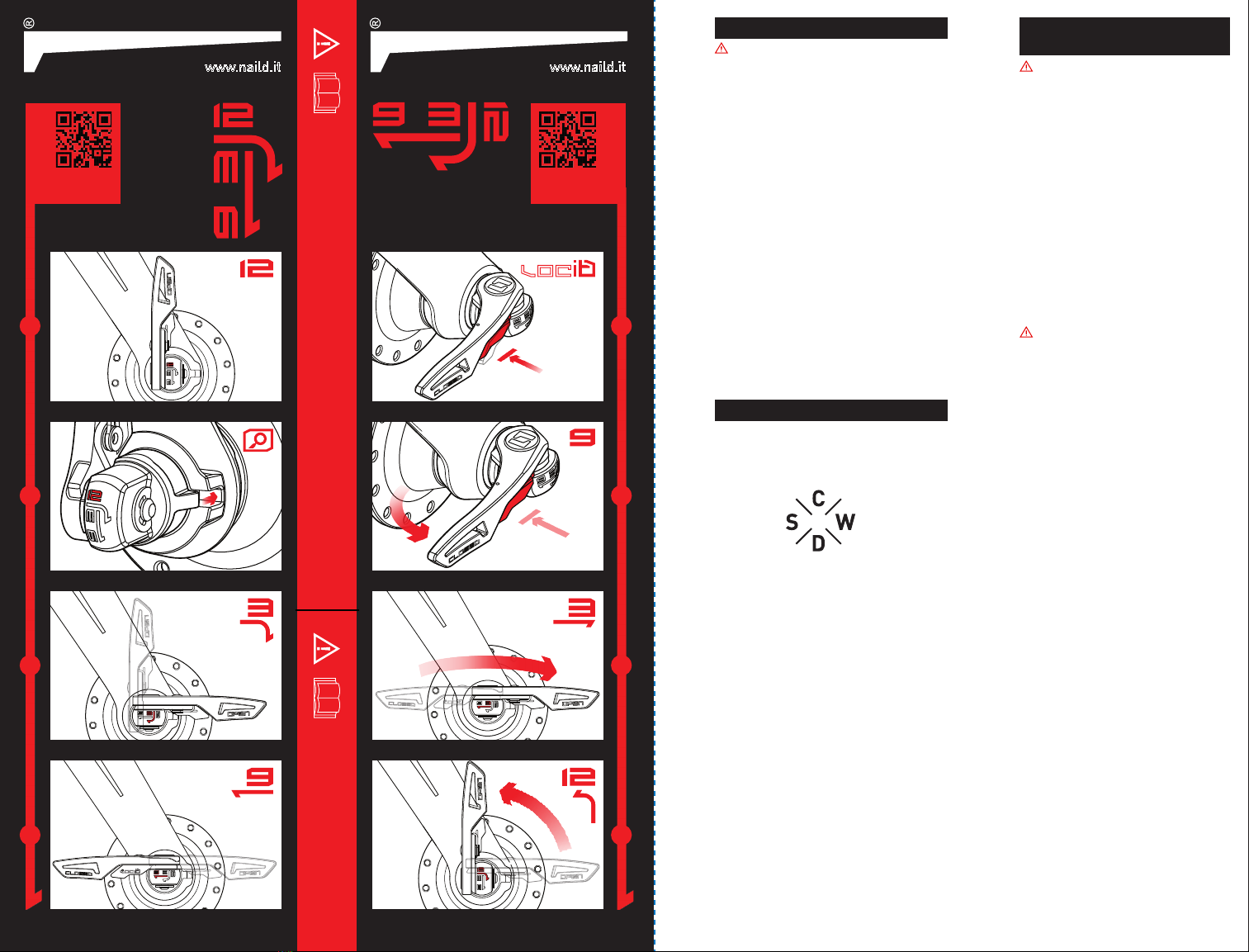
QUICK GUIDE to be
removed by user only
INSTALL
AXLE
QUICK GUIDE
www.naild.it
1
2
3
4
REMOVE
AXLE
QUICK GUIDE
www.naild.it
1
2
3
4
WARNING: BEFORE USING THIS PRODUCT,
READ, UNDERSTAND AND FOLLOW THE
WARNINGS AND INSTRUCTIONS PROVIDED
IN THIS MANUAL. IMPROPER INSTALLATION
CAN RESULT IN SEVERE PERSONAL INJURY
OR DEATH.
If you have any questions, contact the place of
purchase, or a bicycle dealer. A dealer’s manual
for professional and experienced bicycle
mechanics is available on our website (www.
naild.it).
Never use tools to operate the 12-3-9® system
as damage may occur. Hand pressure is all that
is needed.
Do not disassemble or alter this product.
Products are not guaranteed against natural
wear or deterioration from normal use and
aging. See www.naild.it for warranty terms
and conditions.
For maximum performance timely and
appropriate service is mandatory. If unclear
whether the product is in need of service or
repair, contact the place of purchase or a
bicycle dealer.
GENERAL NOTICE GENERAL SAFETY
GUIDELINES
WARNING: BEFORE USING THIS
PRODUCT, READ, UNDERSTAND
AND FOLLOW THE WARNINGS AND
INSTRUCTIONS PROVIDED IN THIS MANUAL.
IMPROPER INSTALLATION CAN RESULT IN
SEVERE PERSONAL INJURY OR DEATH.
The 12-3-9® system requires specific
features that are integral to the frame
and fork for proper use of the system.
Never use the 12-3-9® system on non-
compatible frames and forks. For a list of
compatible frames and forks please visit
www.naild.it
The 12-3-9® system is not compatible with
some hub designs. Do not attempt to use
the 12-3-9® system with non-compatible
hubs. For a list of compatible hubs please
visit www.naild.it.
EVERY TIME YOU RIDE
WARNING: Clamping forces should be
checked before every ride and any time the
wheel is removed and reinstalled. Before
attempting to install the 12-3-9® system
always inspect all surfaces to make sure
they are clean and free from debris and
other matter that would prevent full
engagement.
The 12-3-9® system has been carefully
engineered to be easy and intuitive to set
up and use. Once set up properly and
maintained according to the instructions
in this manual the 12-3-9® system is
very stable and should require very little
adjustment. However, the following safety
guidelines should always be observed to
ensure your 12-3-9® equipped bike is safe
and read to ride.
Always check your 12-3-9® system before
riding to make sure that the wheels are
correctly installed on the bicycle frame.
See www.naild.it for warranty terms and
conditions. Make sure that the 12-3-9®
system levers are in the CLOSED position
with the Locit® trigger fully engaged and
the CLOSED inscription on the end of the
lever visible.
Lift up the bicycle so that the wheel is off
the ground, and give the top of the tire a
few sharp downward blows as shown in the
diagram. The wheel should not be loose or
come off. Also check for side-to-side play
and make sure the disc rotors are properly
aligned and not rubbing. If the rotor is
rubbing then open the 12-3-9® system
and make sure that everything is clean and
properly adjusted and try again.
A misaligned rotor can cause the brakes
to fail resulting in severe personal injury
or death. If you are unsure how to properly
align your brake rotors take the bike to a
dealer or qualified bicycle mechanic.
These checks do not guarantee that the
quick release lever has received adequate
tightening torque. If you are uncertain as to
whether the 12-3-9® system is tightened
correctly, repeat the INSTALL AXLE AND
ADJUSTMENT section of this guide.
The Naild 12-3-9® system employs the
Quadrant Code System to provide a quick visual
reference to the appropriate use, warranty
period, durability and recommended service
intervals. Please refer to the markings on your
product in reference to the Quadrants shown
herein.
Category of Use (C)- the type of riding the
product was intended for on a scale of 1 through
9 with 1 being light recreational use and 9 being
downhill or freeride use.
Warranty Period (W)- warranty period in
months.
Durability Index (D)- level of expected
durability where a higher number indicates a
greater margin of strength and durability within
a given usage category.
Service Interval (S)- recommended service
interval in hours, e.g., 20 would indicate that
the product should be serviced every 20 hours
of riding time.
Regularly clean and inspect your 12-3-9®
system for wear or damage. For example,
lubricating the inside of the Axle Assembly
with a high quality, waterproof grease will help
ensure top performance and extend the life of
the parts. If you are unsure how to clean and
inspect your 12-3-9® system take it to your
place of purchase or a qualified bicycle dealer.
The 12-3-9® system carries a 36 months
warranty on parts and assembly. See www.
naild.it for warranty terms and conditions. A
few things to note will help extend the life of
the system and ensure years of trouble-free
riding. Never force the system to open or close.
Never use anything other hand pressure to
operate the system, no tools are ever required.
Depressing the Locit® trigger until it has fully
disengaged from the lever will prolong it’s life.
QUADRANT CODE SYSTEM
INSTALL AXLE AND ADJUSTMENT
A. With the lever in the Parallel position, rotate the Adjuster Cap clockwise until you feel firm resistance. This will
indicate that the Axle Assembly is fully inserted through the frame/fork and hub and is properly engaged with the
Adjuster Assembly. The system is ready to be closed.
TENSION PRE-ADJUSTMENT
‘3’ TO ‘PARALLEL’
A. From the 3 position, flip the lever halfway so that it is pointing straight out, Parallel to the axle. There should still be very
little tension on the lever at this point. You are now ready to set the pre-adjustment tension.
WARNING: Do not flip the lever to the 9 position yet. If the lever is accidently flipped to the 9 position please refer
to the REMOVE AXLE ASSEMBLY section or damage may occur, resulting in an accident, personal injury and death.
www.naild.it
REMOVE AXLE
‘3’ TO ‘12’
A. Once in the 3 position the lever can now be rotated counter
clockwise to the 12 position.
B. From the 12 position, the Axle Assembly is now disengaged from
the Adjuster Assembly and can be slid out to remove the wheel.
A. If installing for the first time, rotate the Adjuster Cap counter clockwise until strong resistance is felt.
B. With the lever positioned at 12 and the Clocking Tooth at 3 insert the Axle Assembly through the frame/fork and into the hub
ensuring the Clocking Tooth engages with the slot in the fork/frame. There should be little to no resistance.
C. If the sides of the Clocking Tooth do not engage the sides of the locating slot in the frame/fork that means the Axle Assembly is
not inserted far enough into the Adjuster Assembly. To remedy this, rotate the Adjuster Cap clockwise until the Clocking Tooth
engages the sides of the slot but not quite touching the bottom of the slot.
WARNING: Do not rotate the Adjuster Cap so that the Axle Assembly becomes tight against the frame/fork. This will
create too much clamping force and may cause damage, resulting in an accident, personal injury and death.
AXLE INSERTION
‘12’ TO ‘3’
A. With the axle properly inserted and the Clocking Tooth touching the sides of the locating slot. The lever assembly should not be
tight against the frame/fork yet. The lever is now free to rotate clockwise from 12 to 3 smoothly with little resistance.
WARNING: The lever will not rotate unless the axle insertion procedure was followed exactly. Do NOT force the lever to
rotate or damage may occur resulting in an accident, personal injury and death.
B. With the lever in the 3 position the Axle Assembly should now be engaged with Adjuster Assembly. Please note that the Axle
Assembly cannot be removed at this point without rotating the lever back to 12. Also, the 12-3-9® system is not fully closed yet
and will feel loose.
A. First, fully depress Locit® trigger.
B. While still depressing the Locit® trigger, flip the lever open from
9 to 3 position. Do not force the lever. It will not open unless the
Locit® trigger is first fully depressed
‘9’ TO ‘3’
A. Flip the lever from Parallel to the 9 position, feeling for increasing resistance. Do not touch the Locit® trigger during this
motion. If the resistance is too great to close the lever completely so that the Locit® trigger engages, return the lever to
the Parallel position and rotate the Adjuster Cap counter clockwise a few clicks and try again. Similarly, if the lever feels
too loose in the 9 position, depress the Locit® trigger and return the lever to the Parallel position, rotate the Adjuster
Cap clockwise a few clicks and move the lever to the 9 position until the Locit® trigger clicks. A little back and forth
adjustment may be required to properly dial in the clamping force.
WARNING: Do not force the lever or damage may occur. Only hand pressure should be used. Never use tools to
close the lever. Before riding, check that the axle system is completely engaged as per the General Safety Guidelines.
B. Lever torque specification in the CLOSED position is 5.0 – 7.5 N·m (44-66 in·lb)
C. There will be an audible click as the Locit® trigger engages and the CLOSED inscription will be clearly visible at the end
of the lever. The lever now cannot be opened without first depressing the Locit® trigger.
D. Before riding, check that the axle system is completely engaged as per the General Safety Guidelines.
‘PARALLEL’ TO ‘9’
GLOSSARY OF TERMS
C
12-3-9 SYSTEM LOCATION
The 12-3-9® system is located
on the front and/or rear hub of
your bicycle. The
hub is located at
the center of
each wheel.
12-3-9®
References the hand positions
of a clock. (ie., 12 is the 12
o’clock position, 3 is the 3
o’clock position and 9 is the 9
o’clock position.)
Parallel
The parallel position is with
the lever pointing straight
out, or parallel to the axle.
Axle Assembly
The complete axle
assembly including the
lever with Locit® trigger,
Clocking Tooth, and axle.
Locit®
The small, spring-loaded
red trigger on the lever that
prevents the lever from
opening unless depressed.
Clocking Tooth
A small locating tab on
the axle assembly that,
when properly engaged
in the corresponding slot in
the frame or fork, ensures the
lever position references the
12-3-9 clock positions.
Adjuster Assembly
The part of the
12-3-9® system
that is permanently fixed to
the frame or fork including the
Adjuster Cap which adjusts,
sets and retains the proper
clamping forces.
WARNING: Before using this Product, read, understand and follow the warnings and instructions provided in this manual.
Improper installation can result in severe personal injury or death.
*Note: The bike should be in a normal, horizontal position
*Note: Before attempting to install the Axle Assembly inspect all surfaces and make sure they are clean and free from
debris and other matter that would prevent full engagement.
WARNING:
Please read and understand these
terms before installing and using
the 12-3-9® system.

Popular Bicycle Accessories manuals by other brands

Light & Motion Vega LED light owner's manual

Light & Motion

Light & Motion Vega LED light owner's manual

Flyer AC804 instruction sheet

Flyer

Flyer AC804 instruction sheet

Bosch Kiox BUI330 Original operating instructions

Bosch

Bosch Kiox BUI330 Original operating instructions

Specialized SpeedZone Elite owner's manual

Specialized

Specialized SpeedZone Elite owner's manual

FOBO Bike user manual

FOBO

FOBO Bike user manual

Ohlins RXC34 m.1 owner's manual

Ohlins

Ohlins RXC34 m.1 owner's manual

Bike Balance Training Handle Owners installation and operating manual

Bike Balance

Bike Balance Training Handle Owners installation and operating manual

Sigma PURE 1 ats manual

Sigma

Sigma PURE 1 ats manual

Cateye GVolt70.1 HL-EL552G-RC manual

Cateye

Cateye GVolt70.1 HL-EL552G-RC manual

Miche SYNTIUM Manual of maintenance and use

Miche

Miche SYNTIUM Manual of maintenance and use

Hyena E-Road Series user manual

Hyena

Hyena E-Road Series user manual

SIIG Ilumina Rear instruction manual

SIIG

SIIG Ilumina Rear instruction manual

Lupine SL MINI MAX instructions

Lupine

Lupine SL MINI MAX instructions

ROTOR ITA30 installation guide

ROTOR

ROTOR ITA30 installation guide

Cateye Urban Wireless+ instruction manual

Cateye

Cateye Urban Wireless+ instruction manual

Performance Spin Doctor Instructions for use

Performance

Performance Spin Doctor Instructions for use

ROTOR BSA30 quick start guide

ROTOR

ROTOR BSA30 quick start guide

Marzocchi 320 LCR CARBON manual

Marzocchi

Marzocchi 320 LCR CARBON manual

manuals.online logo
manuals.online logoBrands
  • About & Mission
  • Contact us
  • Privacy Policy
  • Terms and Conditions

Copyright 2025 Manuals.Online. All Rights Reserved.