NAIM CONNECTIONS User manual

OWNERS MANUAL
Connection Guide

c
contents
cd players
2 cds
4 cdx
6 cd5
tuners
8 nat 01
9 nat 02
9 nat 05
headphones
10 headline
phono stage
11 stageline
preamplifiers
12 nac 52
14 nac 82
18 nac 102
20 nac 112
a/v processor
22 av2
integrated amplifier
24 nait 5
power amplifiers
28 nap 500
29 nap 135
30 nap 250, nap 180, nap 150
31 nap 140, nap 6-50, nap v175
power supplies
32 supercap, hi-cap
33 flatcap 2
active crossovers
40 snaxo 3-6, snaxo 2-4, ixo 2
introduction
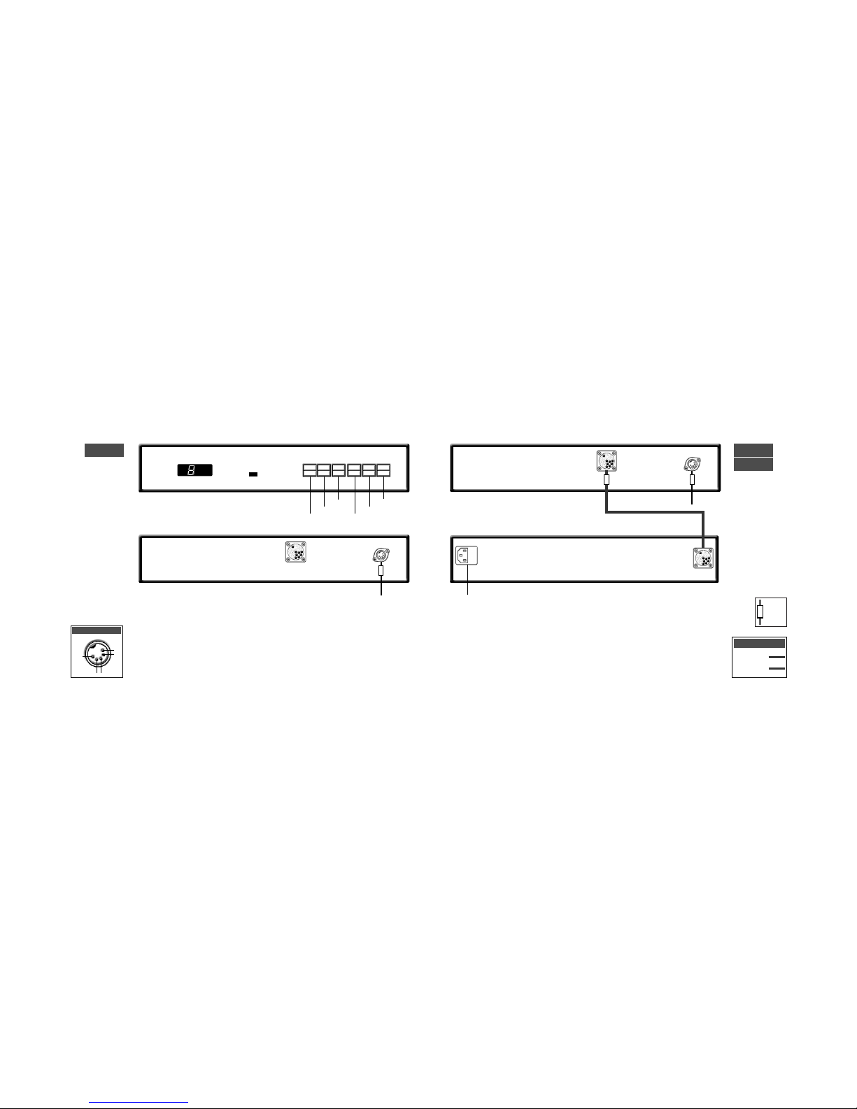
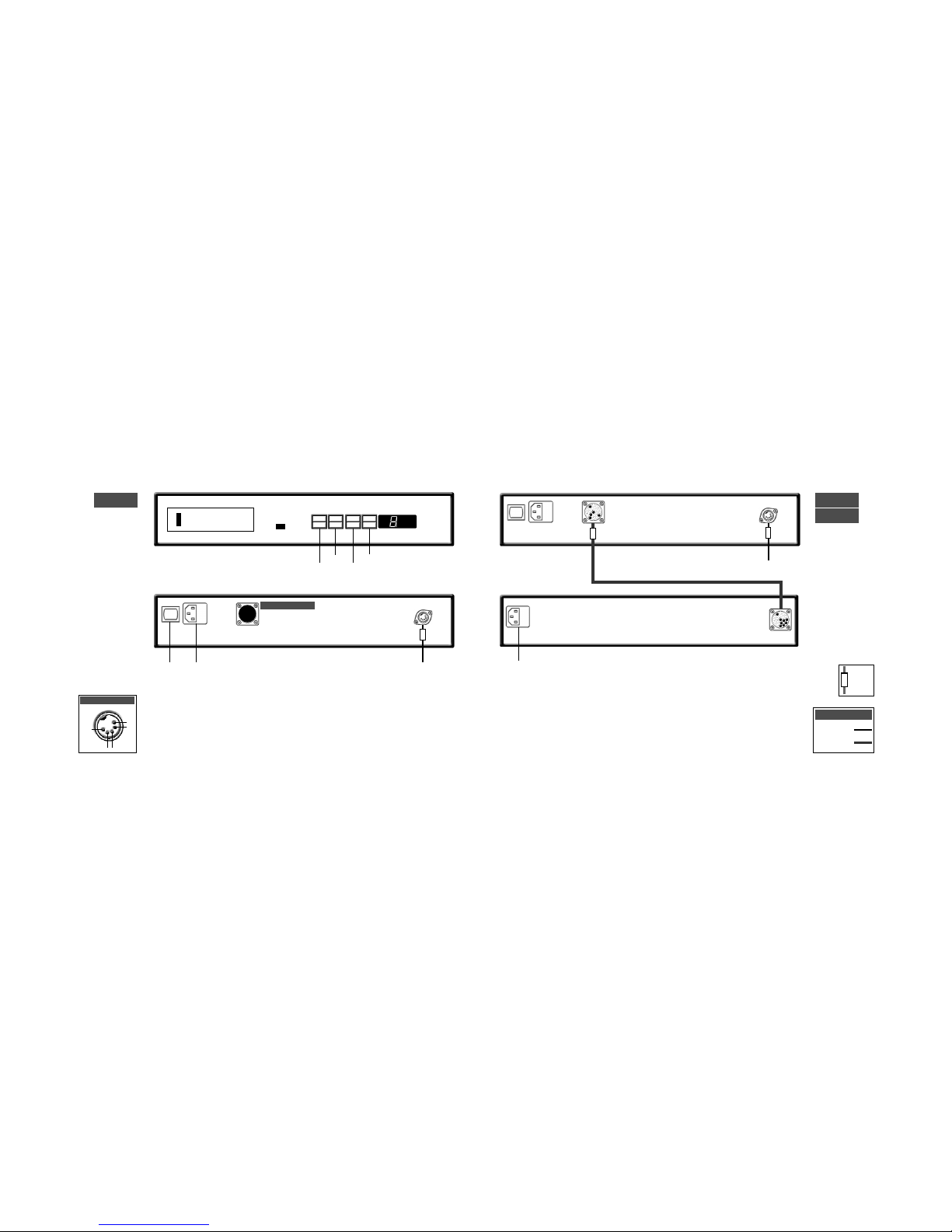
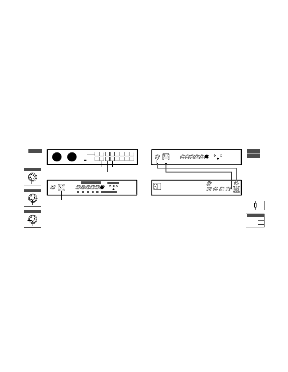
This connection guide collects together illustrations
of product connection panels and many of the most
often used system connection diagrams. Each
illustration and diagram can also be found in the
appropriate product Owners Manual. This guide
should not be seen as a replacement for specific
Owners Manuals as these contain important safety
and installation information.

cable
direction
marker
3
cd players
cds connection to xps power supply
cds
xps
cd players
cds
2
track
time
repeat
program
to preamplifier mains input
to preamplifier
5-5 180˚ DIN
11-11 Burndy
Interconnects
display
previous
next
pause
stop
play
ch1
nc
nc
-ve
ch2
cds output

5
cd players
cdx connection to xps power supply
cdx
xps
cd players
cdx
4
pause
time
repeat
program
link plug fitted
to preamplifier
mains input
power switch
to preamplifier
cable
direction
marker
5-5 180˚ DIN
11-11 Burndy
Interconnects
mains input
note
Do not connect the cdx to mains power.
ch1
nc
nc
-ve
ch2
cdx output
previous
next
stop
play

7
cd players
cd5 connection to flatcap 2 power supply
cd players
6
link plug fitted
to preamplifier
rc5 input
link plug removed
to preamplifier
ch1 nc
nc
-ve
ch2
cd5 output
cable
direction
marker
5-5 180˚ DIN
5-5 240˚ DIN
Interconnects
cd5
flatcap 2
cd5
previous
next
stop
play
note
cd5 players manufactured after April 2001 are fitted
with an RC5 control input. This input is designed to
accept external control signals for multi-room
applications. Contact your dealer for further
information on its use.
mains input
power switch
mains input
power switch
mains input
power switch

9
tuners
tuners
napst
nat 01
8
ch1
nc
nc
-ve
ch2
nat 01 output
nat 01 connection to napst power supply
to preamplifier 75 ohm FM aerial mains input
rc5 input
cable
direction
marker
5-5 180˚ DIN
5-5 240˚ DIN
Interconnects
ch1 nc
nc
-ve
ch2
nat 02/05 output
75 ohm FM aerial
to preamplifier
75 ohm FM aerial to preamplifier
nat 05
nat 02
note
The RC5 input is designed to accept
external control signals for multi-room
applications. Contact your dealer for
further information on its use.
mains input
power switch
power switch
mains input

to:
nac 52, nac 82, nac 102:
socket 4, 5 or 6.
nac 112, nait 5:
socket 3, 4 or 5.
11
phono stage
stageline connection to nait 5 or nac 112
stageline connection to flatcap 2
stageline
headphone amplifier
headline connection to napsc or hi-cap power supply.
headline
10
from napsc
to:
nac 52, nac 82, nac 102:
socket 4, 5 or 6.
nac 112, nait 5:
socket 3, 4 or 5.
all link plugs fitted cover fitted
5-2 SLIC
Captive 5/180˚ DIN
Interconnects
cable
direction
marker
hi-cap
to preamp. 4
to 5 pin
interconnect
required
mains input
mains input
power switch
mains input
power switch
5-5 240˚DIN
4-5 DIN
Interconnects

13
preamplifiers
nac 52 connection to supercap power supply
nac 52
supercap
preamplifiers
nac 52
12
6 5 4 3 2a 2b (blank fitted)
1
high level inputs phono input
digital
power supply
audio power supply
ch1
nc
nc
-ve
ch2
inputs 3 & 2a
ch1
ch1
ch2
-ve
ch2
inputs 6, 5 & 4
input 2b
+ve
ch1
ch2
-ve
+ve
cable
direction
marker
5-5 240˚ DIN
16 -16 Burndy
Interconnects
1
inputs
mono
volume balance
mute 2a/b
3
4
5
6
rec
source
to nap 140, 150 or 180 power amplifiers (4 pin DIN) or nap 250 power amplifier (4 DIN-XLR)
to nap 135 or nap 500 power amplifiers (4 pin to XLR)
mains input

15
preamplifiers
nac 82 connection to nap 140, 150 and nap 180 power amplifiers
nac 82 connected to one hi-cap or flatcap 2
nac 82
hi-cap
preamplifiers
nac 82
14
6 5 4 3 2
1
high level inputs
outputs
phono input
napsc
link plugs fitted
napsc
to nap 140,150
& 180 power
amplifiers
link plug fitted
napsc
ch1
nc
nc
-ve
ch2
inputs 3 & 2
ch1
ch1
ch2
-ve
ch2
inputs 6, 5 & 4
note
The napsc power supply must
be connected to the nac 82 at
all times.
4-4 DIN to nap 140, 150 & 180
4 DIN-XLR to nap 250
4 DIN-XLR to
nap 135 & 500
cable
direction
marker
4-4 DIN
5-5 240˚ DIN
Interconnects
1
inputs
mono
volume balance
mute 2
3
4
5
6
rec
source
mains input

17
preamplifiers
nac 82 connection to supercap
nac 82
supercap
preamplifiers
nac 82 connection to two hi-caps or flatcaps
nac 82
hi-cap
16
napsc
4-4 DIN to nap 140, 150 & 180
4 DIN-XLR to nap 250
4 DIN-XLR to
nap 135 & 500
all link plugs removed
napsc
all link plugs removed
4-4 DIN to nap 140, 150 & 180
4 DIN-XLR to nap 250
4 DIN-XLR to nap 135 & 500
cable
direction
marker
5-5 240˚ DIN
Interconnects
cable
direction
marker
5-5 240˚ DIN
Interconnects
note
Sound quality will be severely impaired if power
supplies are mixed. A flatcap together with a hi-cap
for example. Similarly, both outputs of a Flatcap 2
should not be used simultanesously to power one
preamp.
mains input mains input mains input
do not use
do not use

19
preamplifiers
nac 102 connection to hi-cap or flatcap
nac 102
hi-cap
preamplifiers
nac 102 connection to one power amplifier with internal power supply
nac 102
18
1b
high level inputs
outputs phono input
6 5 4 3 2 1a
4-4 DIN to nap 140, 150 & 180
note
When connecting a hi-cap without an napsc, the
large link plug must be fitted (see previous page).
link plugs
fitted
volume balance
inputs 3, 2 & 1a
inputs 6, 5 & 4
ch1 nc
nc
-ve
ch2
ch1 ch1
ch2
-ve
ch2
napsc
(optional)
link plugs removed
4-4 DIN to nap 140, 150 & 180
4 DIN-XLR to nap 250
4 DIN-XLR to
nap 135 & 500
cable
direction
marker
5-5 240˚ DIN
Interconnects
1
inputs
monitor
mute 2
3
4
5
6
mains input

21
preamplifiers
nac 112 connection to flatcap 2
nac 112
preamplifiers
nac 112
20
link plug & cover fitted
cover fitted
monitor
mute
cd
tuner
tape a/v
aux 1
aux 2
volume
4-4 DIN to nap 140, 150 & 180 aux 1
tape
a/v tuner
aux 2
cd
note
The aux 2 input is provided with two sockets. The
left hand socket, fitted on delivery with a blanking
cover, is intended for use with a Stageline or Prefix
phono stage and incorporates an appropriate DC
power supply.
ch1 ch1
ch2
-ve
ch2
tape, a/v & aux 1
inputs
ch1 nc
nc
-ve
ch2
cd, tuner & aux 2
inputs
nac 112 connection to one power amplifier with internal power supply
to nap 140, 150,
180 & 250 power
amplifiers
to nap 135 & 500
power amplifiers
for cd5, headline or
stageline. Additional
interconnects
required. cable
direction
marker
5-5 240˚ DIN
Interconnects
flatcap 2
mains input
power switch

dig
out
2
23
a/v processor
av2 connection to nap v175
av2
nap v175
a/v processor
av2
22
V1 MUL
encoder input mode
mains
input
rear
out
cen
out
sur
out
fr’t
out
sub
out
rc5
in
dig
out
1
dig
in
1
data
i/o
vs
1
i/o
rec
out
rec
out
ch1
left
an’g
in 3
dig
in
2
dig
opt
out
dig
opt
in 2
dig
opt
in 1
an’g
in 6
an’g
in 4
ch 2
right
an’g
in 2
(vip)
an’g
in 1
(vip)
power
switch
ch1
nc
ch2
-ve
rear, surround &
front outputs
centre output
cen
nc
(sub)
-ve
analogue in 3
ch1 ch1
front
out
ch2
-ve
ch2
analogue in 2
ch1 nc
nc
-ve
ch2
analogue in 1
ch1 nc
nc
-ve
ch2
analogue in V2 & V1 multi mode
V2 V1
cen
in ch1
ch2
-ve
sub
in
ch1 ch1
ch2
-ve
ch2
rear
in surr
in
front
in
mains
input
power
switch
- ++ - - +
4-4 DIN
Interconnects
to nap 140, 150, 180 &
250 power amplifiers
to nap 140, 150, 180 &
250 power amplifiers
to preamp

25
integrated amplifier
nait 5 connection to flatcap 2
nait 5
integrated amplifier
nait 5
24
link plugs/covers fitted
aux 1
tape
a/v
tuner
aux 2
out A
out B
in
cd
monitor
mute
cd
tuner
tape a/v
aux 1
aux 2
volume
mains input
power switch
ch1 ch1
ch2
-ve
ch2
tape, a/v & aux 1
inputs
ch1 nc
nc
-ve
ch2
cd, tuner & aux 2
inputs
+V in +V in
ch1
-ve
ch2
signal out A
for cd5, headline or
stageline. Additional
interconnects
required.
flatcap 2
mains input
power switch
link plugs removed, cover fitted
mains input
power switch
cable
direction
marker
4-4 DIN
5-5 240˚ DIN
Interconnects
speakers
ch1, left
speakers
ch2, right
- ++ -
- ++ -

27
integrated amplifier
nait 5 connection to flatcap 2 and nap150
nait 5
integrated amplifier
nait 5 connection to nap 150
nap 150
nait 5
26
link plug fitted
mains input
power switch
mains input
power switch
note
Do not connect the nait 5 to mains power.
cable
direction
marker
4-4 DIN
Interconnects
mains input
power switch
link plugs removed flatcap 2
nap 150
cable
direction
marker
4-4 DIN
5-5 240˚ DIN
Interconnects
speakers
ch1, left
speakers
ch2, right
- ++ -
speakers
ch1, left
speakers
ch2, right
- ++ -
note
Do not connect the nait 5 to mains power.

29
power amplifiers
nap 500 connection to na ps500 power supply
nap 135
power amplifiers
na ps500
nap 500
28
2
1
-venc
ch2
Socket 2
-vech1
nc
Socket 1
-venc
ch2
Socket 2
-vech1
nc
Socket 1
speakers
ch1, left
speakers
ch2, right
mains input
to preamp
power supply.
ch 1, left
to preamp
power supply.
ch 2, right
9-9 Burndy
Interconnects
mains input to power supply fan
2
1
fan
2
1
mains input to power supply
speakers
ch1, left
speakers
ch2, right
- +
- +
- +
+ -

31
power amplifiers
power amplifiers
nap 180
nap 150
nap 250
30
-ve
ch2
ch1
+ve
mains input to power supply
mains input to preamplifier
or power supply
to preamplifier
or power supply
speakers
ch1, left
speakers
ch2, right
-vech1
ch2
nap 250
nap 180
nap 140
mains
input
power
switch
to preamplifier
or power supply
nap 140
nap 6-50
-ve
ch2
+ve
ch1
mains
input
zone 1
speakers
ch 1, left
zone 2
speakers
ch 1, left
zone 1
speakers
ch 2, right
zone 2
speakers
ch 2, right
zone 3
speakers
ch 2, right
zone 3
speakers
ch 1, left
- + - + - +
- + - + - +
mains input
zone 1
trigger
zone 3
zone 2
speakers
ch1, left
speakers
ch2, right
speakers
ch1, left
speakers
ch2, right
- ++ -
- ++ -
- ++ -
speakers
ch1, left
speakers
ch2, right
- ++ -
mains
input
power
switch
to av
processor
speakers
ch1, left
speakers
centre
- ++ -
napv 175
nap 150
ch1
+ve
ch2
-ve
napv 175 Skt 2
ch1
nc
ch2
-ve
napv 175 Skt 1
centre
nc
nc
-ve
ch1
nc
ch2
-ve
nap 6-50
speakers
ch2, right
- +
2
1

33
power supplies
power supplies
hi-cap
supercap
32
mains input
1 3 4 5 7
6
2
hi-cap
Socket 4
+ve
ch1
ch2
-ve
+ve
ch1
nc
-ve
ch2
hi-cap
Sockets 1, 2 & 3
ch1
nc
ch2
-ve
Sockets 2, 3, 4 & 6
supercap
Socket 1
+ve
ch1
ch2
-ve
+ve
supercap
Socket 2
+ve
nc
nc
-ve
+ve
ch1
nc
-ve
ch2
supercap
Sockets 3, 4, & 5
mains input
1 2 3 4
note
supercap socket 6 for nac 52 only
supercap socket 7 for nac 52 and snaxo only
mains input
power switch
1 2 3 4 5 6
flatcap 2
+ve +ve
ch1
-ve
ch2
Sockets 1 & 5
note
socket group 1, 2 3 & 4. and socket group 5 &
6 are entirely seperate.

35
power supplies
nac 52 connection to supercap with second supercap for snaxo
nac 52
supercap
supercap
power supplies
nac 52 connection to supercap with optional extra hi-cap for snaxo
supercap
hi-cap
nac 52
34
to snaxo
to snaxo
16 -16 Burndy
5-5 240˚ DIN
4-4 DIN
Interconnects
cable
direction
marker
16 -16 Burndy
5-5 240˚ DIN
4-4 DIN
Interconnects
cable
direction
marker
mains input
mains input
mains input
mains input

37
power supplies
nac 82 connection to supercap with extra hi-cap for snaxo
nac 82
supercap
hi-cap
power supplies
nac 82 connection to two hi-caps with extra flatcap 2 for snaxo
36
nac 82
hi-cap
napsc
mains input
power switch
mains input
all link plugs removed
to snaxo
flatcap 2
cable
direction
marker
cable
direction
marker
4-4 DIN
5-5 240˚ DIN
Interconnects
4-4 DIN
5-5 240˚ DIN
Interconnects
for cd5, headline or
stageline. Additional
interconnects
required.
napsc
all link plugs removed
to snaxo
mains input
mains input
This manual suits for next models
28
Table of contents
Other NAIM Stereo System manuals
Popular Stereo System manuals by other brands

Roland
Roland V-Drums TD-3 user manual

Bose Professional
Bose Professional L1 PRO32 + SUB1 Preliminary Technical Data

Sony
Sony HCD-FL7D - System Components Service manual

Innovative Technology
Innovative Technology ITVS-750 user manual

Philips
Philips MCM765 user manual

Telestar
Telestar Imperial DABMAN i510 BT user manual