manuals.online logo
Brands
  1. Home
  2. •
  3. Brands
  4. •
  5. NAiS
  6. •
  7. Cables And Connectors
  8. •
  9. NAiS CT-2 User manual

NAiS CT-2 User manual

CT-2
CONNECTOR
TERMINAL
COMPACT CONNECTOR
TERMINAL FOR
REDUCED WIRING
Pressure connector
connect type
Wire-direct connect type
FEATURES
• One-touch wiring with the various
controller types greatly reduces the
time required for wiring operations.
• Compact space-saving design
Design and dimensions match those for
the RT-2 relay terminal.
• Wide variation of pole: 20, 30, 34 and
40 poles
• Available in pressure connector con-
nect type and wire-direct connect
type
The direct connect type is a compact 62
×
52 mm 2.441
×
2.047 inch (20P type).
• Exclusive cables can be provided
• Integrated AXM connector (comply-
ing to MIL Standard, Long lever type)
TYPICAL APPLICATIONS
I/O interface for PLCs, personal comput-
ers and various types of controllers.
ORDERING INFORMATION
Ex. CT2 M
Installation type
Blank:
M:
C20
DIN rail mounting
type
Direct mounting
type
Termination type
Blank:
C:
Pressure connector
connect type
Wire-direct
connect type
No. of poles
20: 20 poles
30: 30 poles
34: 34 poles
40: 40 poles
TYPES
1. DIN rail mounting type 2. Direct mounting type
Connection
method No. of poles Part No. Packing quantity
Inner carton Outer carton
Pressure
connector
connect type
20 CT2-20
1 pc. 20 pcs.
30 CT2-30
34 CT2-34
40 CT2-40
Wire-direct
connect type
20 CT2-C-20
30 CT2-C-30
34 CT2-C-34
40 CT2-C-40
Connection
method No. of poles Part No. Packing quantity
Inner carton Outer carton
Pressure
connector
connect type
20 CT2-M-20
1 pc. 20 pcs.
30 CT2-M-30
34 CT2-M-34
40 CT2-M-40
Wire-direct
connect type
20 CT2-MC-20
30 CT2-MC-30
34 CT2-MC-34
40 CT2-MC-40
SPECIFICATIONS
Rated voltage 125 V AC
Rated current 1 A
Breakdown voltage 250 Vrms for in min.
Insulation resistance 100 M
Ω
(at 500 V DC megger)
Fasten torque
Pressure connector connect type:
0.3 to 0.5 N·m {3 to 5 kgf·cm}
Wire-direct connect type
0.2 to 0.4 N·m {2 to 4 kgf·cm}
Ambient temperature 0
°
C to +55
°
C +32
°
F to +131
°
F
CONNECTOR
• Applicable connector (socket)
• Applicable flat cable
Standard wire: standard pitch (1.27 mm 0.050 inch)/
conductor #28 (7 wire/0.127 dia.)
Product name No. of poles Part No.
MIL type AXM Flat Cable Connector
20 AXM120415
30 AXM130415
34 AXM134415
40 AXM140415
All Rights Reserved © COPYRIGHT Matsushita Electric Works, Ltd.
CT-2
TERMINAL BLOCK
1. Pressure connector connect type
• Applicable electrical wire
0.25 to 1.65 mm
2
.01 to .065 inch
• Applicable wire-pressed terminals
mm inch
2. Wire-direct connect type
When wiring screw-clamped terminal blocks, strip the lead wires
and connect them properly.
3 min.
.118 min.
5.6 max.
.220 max.
4.5 min.
.177 min.
4
.157
3 dia. min.
.118 dia. min.
5.6 max.
.220 max.
4.5 min.
.117 min.
4
.157
Stripping length Recommended wire
8 to 10 mm
.315 to .394 inch
•0.128 to 1.318 mm .005 to 0.52 inch
•0.4 to 1.3 mm dia. .016 to .051 inch dia.
DIMENSIONS
1. DIN rail mounting type
Pressure connector connect type (20 poles)
A1
B1
B2
A1
B1
A4A3A2
B3 B4 B5
A6A5
B6
A8A7
B7 B8
A10A9
A10
B10B9
B10
20-M3 .118 terminal screw
98±1
3.858±.039
6.2±0.3
.244±.012
7.62±0.3
.300±.012
42±0.6
1.654±.024
52±1
2.047±.039
Wire-direct connect type 20 poles
A1
B1
A10
B10
62±1
2.441±.039
5.08±0.3
.200±.012
52±1
2.047±.039
42±0.6
1.654±.024
Pressure connector connect type (30 poles)
A2A1
B1 B2
A3
B3
A1
B4
B1
A4 A6A5
B5 B6
A7
B7
A15
B11
A11
B9
A8
B8
A9 A10
B10
A13A12
B12
A15
B13
A14
B14 B15
B15
30-M3 .118 terminal screw
134±1
5.276±.039
7.62±0.3
.300±.012 6.2±0.3
.244±.012
Wire-direct connect type (30 poles)
A1
B1
A15
B15
98±1
3.858±.039
5.08±0.3
.200±.012
Pressure connector connect type (34 poles)
B1
A2A1
B2
A5
B5B3
A4A3
B4
A1
B1
B6
A7A6
B7
A9A8
B8 B9
A11A10
B10 B11
A12
B13B12 B14
A17
B17
A13
B16
A15A14
B15
A17A16
B17
34-M3 .118 terminal screw
170±1
6.693±.039
7.62±0.3
.300±.012 6.2±0.3
.244±.012
Wire-direct connect type 34 poles
A1
B1
A17
B17
98±1
3.858±.039
5.08±0.3
.200±.012
Pressure connector connect type (40 poles)
A2A1
B1 B2
A4A3
B3 B4
A5
B5
A6
B6
A1
A8A7
B8B7 B15B11
B9
A10A9
B10
A13
B13
A12A11
B12
A14
B14
40-M3 .118 terminal screw
A15
A20
B20
A19A17A16
B16 B17
A18
B18 B19
A20
B20
B1
170±1
6.693±.039
7.62±0.3
300±.012 6.2±0.3
.244±.012
Wire-direct connect type (40 poles)
A1
B1
A20
B20
134±1
5.276±.039
5.08±0.3
.200±.012
mm inch
All Rights Reserved © COPYRIGHT Matsushita Electric Works, Ltd.
CT-2
2. Direct mounting type
Pressure connector connect type (20 poles)
A1
B1
B2
A1
B1
A4A3A2
B3 B4
A6A5
B5 B6 B7
A8A7
B8
A10A9
A10
B10B9
B10
20-M3 .118 terminal screw
2-M4 .157 screw mounting position
42±0.6
1.654±.024
52±1
2.047±.039
98±1
3.858±.039
7.62±0.3
.300±.012 6.2±0.3
.244±.012
106±0.5 4.173±.020
(M4 .157 screw mounting pitch)
115±1
4.528±.039
Wire-direct connect type 20 poles
A10
B10
A1
B1
42±0.6
1.654±.024
52±1
2.047±.039
62±1
2.441±.039
5.08±0.3
.200±.012
79±1
3.110±.039
2-M4 .157 screw mounting position
70±0.5 2.756±.020
(M4 .157 screw mounting pitch)
Pressure connector connect type (30 poles)
B2
A1
B1
A3A2
B3
A1
B1
A6A4
B4
A5
B5 B6
A7
B7 B11
A8
B8
A9 A10
B10B9
A12A11
B12 B13
A13
A15
A14
B14
B15
A15
B15
30-M3 .118 terminal screw
134±1
5.276±.039
7.62±0.3
.300±.012 6.2±0.3
.244±.012
151±1
5.945±.039
142±0.5 5.591±.020
(M4 .157 screw mounting pitch)
Wire-direct connect type (30 poles)
A1
B1
A15
B15
98±1
3.858±.039
5.08±0.3
.200±.012
115±1
4.528±.039
106±0.5 4.173±.020
(M4 .157 screw mounting pitch)
Pressure connector connect type (34 poles)
A1
B1
A5
B5B3
A2 A4A3
B4
A7A6
B6 B7
A9A8
B8 B9
A11A10
B10 B11 B14
A17
B17
A13A12
B13B12 B16
A15A14
B15 B17
A17A16
B1
A1
B2
34-M3 .118 terminal screw
170±1
6.693±.039
7.62±0.3
.300±.012 6.2±0.3
.244±.012
187±1
7.362±.039
178±0.5 7.008±.020
(M4 .157 screw mounting pitch)
Wire-direct connect type 34 poles
B1
A17A1
B17
98±1
3.858±.039
5.08±0.3
.200±.012
115±1
4.528±.039
106±0.5 4.173±.020
(M4 .157 screw mounting pitch)
Pressure connector connect type (40 poles)
A2
B2
A4A3
B3 B4
A1
B1
A6A5
B5 B6
A1
B1
B15
A20
B20
B11 B13B12 B14 B16
A15A13A12 A14 A17A16
B17
A18
B18
B9
A8A7
B8B7
A10A9
B10
A11 A19
B19
A20
B20
40-M3 .118 terminal screw
170±1
6.693±.039
7.62±0.3
.300±.012 6.2±0.3
.244±.012
187±1
7.362±.039
178±0.5 7.008±.020
(M4 .157 screw mounting pitch)
Wire-direct connect type (40 poles)
A1
B1
A20
B20
134±1
5.276±.039
5.08±0.3
.200±.012
151±1
5.945±.039
142±0.5 5.591±.020
(M4 .157 screw mounting pitch)
mm inch
All Rights Reserved © COPYRIGHT Matsushita Electric Works, Ltd.
CT-2
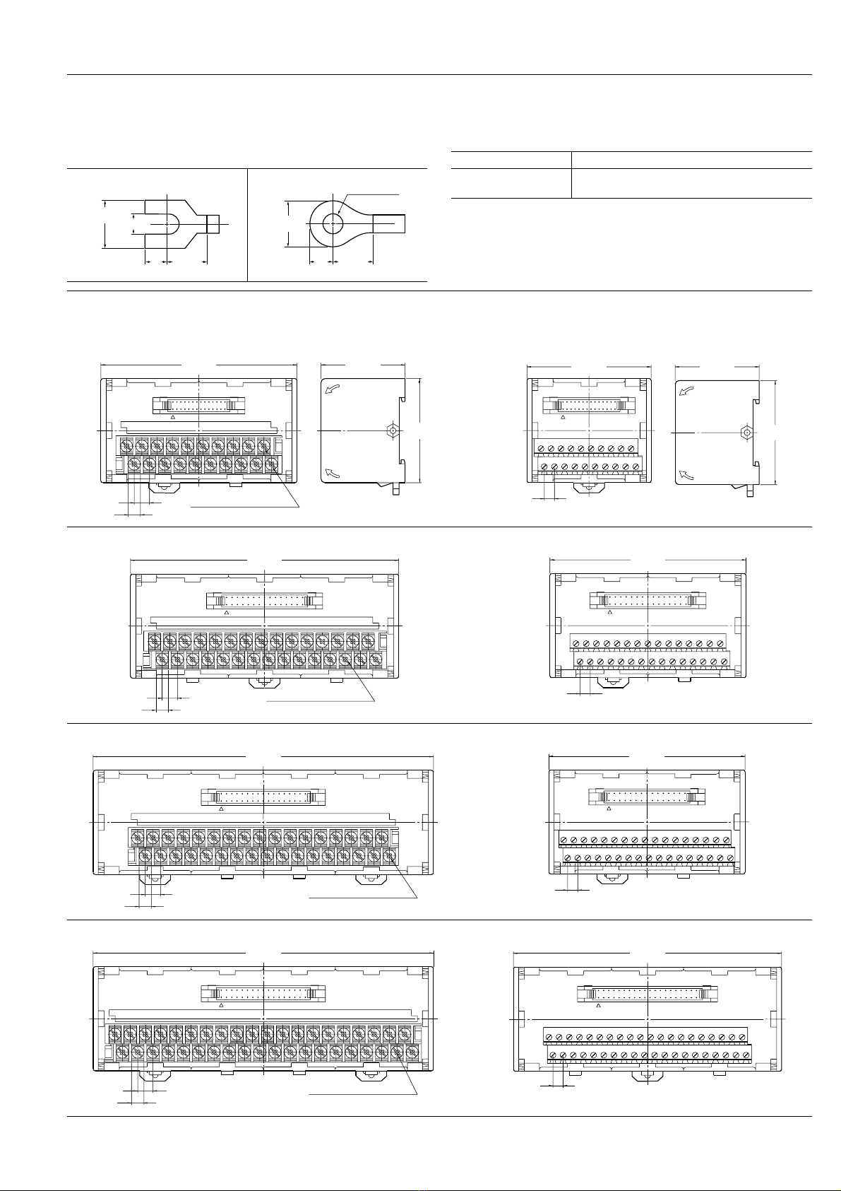
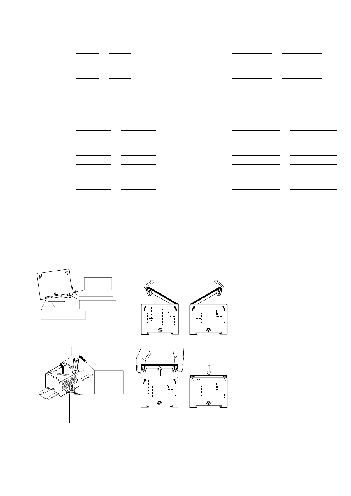
SCHEMATIC (Top View)
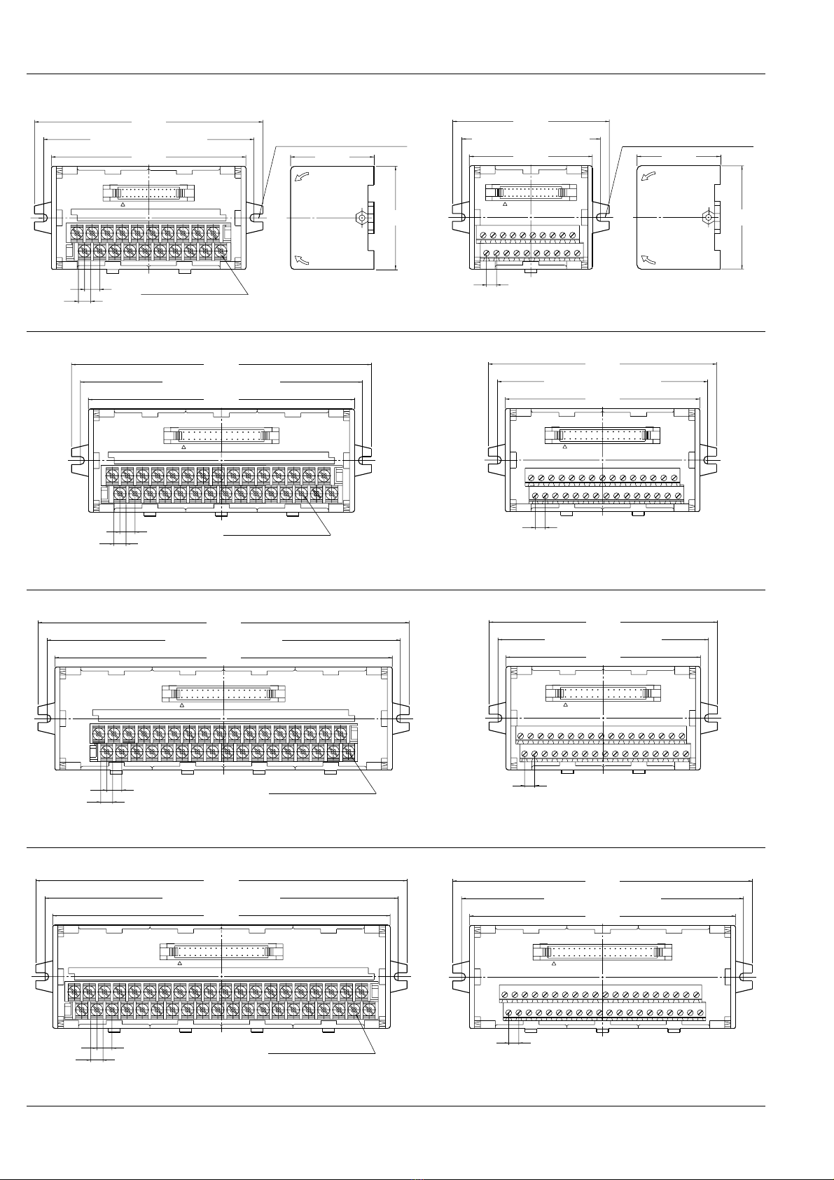
20 poles
30 poles
34 poles
40 poles
A
A
1Connector No.
Terminal No.
(from left on the lower stage)
2345678910
12345678910
B
B
1Connector No.
Terminal No.
(from left on the upper stage)
2345678910
12345678910
A
A
1 2 3 4 5 6 7 8 9 101112131415
1 2 3 4 5 6 7 8 9 101112131415
B
B
1 2 3 4 5 6 7 8 9 101112131415
1 2 3 4 5 6 7 8 9 101112131415
Connector No.
Terminal No.
(from left on the lower stage)
Connector No.
Terminal No.
(from left on the upper stage)
A
A
1 2 3 4 5 6 7 8 9 1011121314151617
1 2 3 4 5 6 7 8 9 1011121314151617
B
B
1 2 3 4 5 6 7 8 9 1011121314151617
1 2 3 4 5 6 7 8 9 1011121314151617
Connector No.
Terminal No.
(from left on the lower stage)
Connector No.
Terminal No.
(from left on the upper stage)
A
A
1 2 3 4 5 6 7 8 9 1011121314151617181920
1 2 3 4 5 6 7 8 9 1011121314151617181920
B
B
1 2 3 4 5 6 7 8 9 1011121314151617181920
1 2 3 4 5 6 7 8 9 1011121314151617181920
Connector No.
Terminal No.
(from left on the lower stage)
Connector No.
Terminal No.
(from left on the upper stage)
CAUTIONS FOR USE
1. Installation
1) Perform mounting hole cutout accord-
ing to the panel cutout drawings.
2) When installing the unit on a DIN rail,
use the DIN rail locking lever on the side
of the unit. Installation is accomplished by
simply fitting the unit onto the rail and
pressing gently.
3) To remove the unit from the DIN rail,
use a flat head screwdriver to pull out the
DIN rail locking lever.
4) Be careful not to drop or shock the unit.
Excessive shock such as dropping may
cause damage or malfunction.
2. Removal of cover
1) Insertions and withdraws of connector
can be done by lifting the cover like
1
.
2) Wiring to the terminal can be done by
lifting the cover like
2
.
3) Removal of the cover can be done by
lifting it like
3
.
4) In case of resetting the cover, please
push the cover like
4
.
3. Wiring and circuit configuration
1) Make all connections according to the
schematic.
2) When wiring power lines or power ca-
bles, twisted pair treatment (standed wire
treatment) should be done in order to im-
prove noise resistance.
3) In order to improve noise resistance,
class 3 grounding of the control panel is
recommended.
4) Turn off the power before connecting/
disconnecting connector cables.
4. Operating environment
1) Use the product at ambient operating
temperature between 0
°
C and 55
°
C 32
°
F
and 131
°
F.
2) The main unit is made of resin; there-
fore, do not use it in areas where it may
come in contact with (or be exposed to)
organic solvents such as benzine, thinner,
and alcohol or strong alkaline substances
such as ammonia and caustic soda.
3) Do not use the product in areas where
it may be exposed to flammable gases,
corrosive gases, excessive dust, or mois-
ture, or areas where it may be subjected
to strong vibration or shock.
5. Transporting and storage
1) If the product is subjected to extreme
vibration while being transported, the re-
lays may become detached, the lead may
become bent, and the unit may become
damaged. Handle the inner and outer
boxes with care.
2) If the product is stored in an extremely
adverse environment, visible defects and
deterioration of performance characteris-
tics may result. We recommend the fol-
lowing storage conditions.
•Temperature: 5 to 30
°
C 41 to 86
°
F
•Humidity: Max. 60% R.H.
•Environment: No hazardous sub-
stances such as sulfurous acid gases
and little dust.
DIN rail locking lever
DIN rail
1
2
3
First push in
the DIN rail
locking lever.
Hook the holders on the
unit over the DIN rail.
Press the unit onto
the DIN rail.
1
2
3
Insert the tip of the
flat head screwdriver
into the slot in the
DIN rail locking lever.
Move the
screwdriver in
the direction
of the arrows,
and pull out
the lever.
Remove the unit from
the DIN rail.
12
34
All Rights Reserved © COPYRIGHT Matsushita Electric Works, Ltd.

This manual suits for next models

16

Popular Cables And Connectors manuals by other brands

Tellur TLL155384 user manual

Tellur

Tellur TLL155384 user manual

Roland digital snake S-4000-SP owner's manual

Roland

Roland digital snake S-4000-SP owner's manual

Mychanic 52752 operating instructions

Mychanic

Mychanic 52752 operating instructions

foxunhd FX-SP01 operating instructions

foxunhd

foxunhd FX-SP01 operating instructions

Philips SWV3432W Specifications

Philips

Philips SWV3432W Specifications

Philips Sonicare 300 SerieS user manual

Philips

Philips Sonicare 300 SerieS user manual

RaidSonic Icy Box IB-SPL1081 quick start guide

RaidSonic

RaidSonic Icy Box IB-SPL1081 quick start guide

Philips SWV3601S/10 user manual

Philips

Philips SWV3601S/10 user manual

Goobay 44415 user manual

Goobay

Goobay 44415 user manual

Philips SWV2809W Specifications

Philips

Philips SWV2809W Specifications

DH Instruments MPG1 WITH PG7302 instruction sheet

DH Instruments

DH Instruments MPG1 WITH PG7302 instruction sheet

Hubbell HBLC40123 installation instructions

Hubbell

Hubbell HBLC40123 installation instructions

Philips SWA7537W/10 user manual

Philips

Philips SWA7537W/10 user manual

Philips SWV2390 Specifications

Philips

Philips SWV2390 Specifications

Philips SWA3203S/10 Information

Philips

Philips SWA3203S/10 Information

Philips SWV3530 Specifications

Philips

Philips SWV3530 Specifications

Waitsfield Cable DCX700 quick start guide

Waitsfield Cable

Waitsfield Cable DCX700 quick start guide

Siemens 3MT8040 Series operating instructions

Siemens

Siemens 3MT8040 Series operating instructions

manuals.online logo
manuals.online logoBrands
  • About & Mission
  • Contact us
  • Privacy Policy
  • Terms and Conditions

Copyright 2025 Manuals.Online. All Rights Reserved.