manuals.online logo
Brands
  1. Home
  2. •
  3. Brands
  4. •
  5. Nakamichi
  6. •
  7. Cassette Player
  8. •
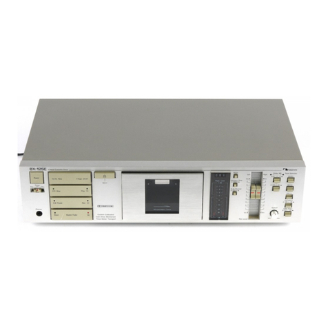
  9. Nakamichi BX-2 User manual

Nakamichi BX-2 User manual

Nakamichi
Service
Manual
Nakamichi
BX-2
2
Head
Cassette
Deck
Pn
BCP sme
CONTENTS
1
GONOr
AE
4
sl
fs
55d
Gnd
eGR
Saya
bigs
Soe
ee
a
aw
Las
eR
RL
ST
Gown
Osco
leeEsae,
Sto,
Bieta
hs ak
oP
ASME
RI
Gs
atte
Moadite
rasta
Sedona
9,
‘Mechanical
Adjustments:
....
56.05.06
6
605
ese
oe
bre
ee
RS
BED
we
EIS
OO
ON
ee
we
eg
bases
2.
1.
Tape
Guide
Height
Check
for
Record/Playback
Head
and
Erase
Head.
.........-.02200000-
2.
2.
Head
*Base:Stroke:
Cheek:
ie
seciic
ts
3
ater
aes
seen
ALG.
wag
a
aied
Ole
Saas
BEE,
teclan
ab
foes
aoa
aS;
ieee
2.
3.
Record/Playback
Azimuth
Alignment
and
Height
Check
.....
0...
0.
ccc
ec
ee
te
eee
2.
4.
Pressure
Adjustment
of
Pressure
Roller...
0...
0...
cee
ee
ee
ne
ete tee
eens
2.
5.
Tape
Travelling
Check
oscg-5.5
6.008
sewn
S
baad
b
8a
ee
Bak
b,
Dawe
the
Male
a
ra
Ber
Sas
Beare
eae,
2
2.
6.
Eject
Damper
Adjustment
...
0...
2...
ee
ete
eee
ee
tee
eee
eens
2.
7.
Reel
Motor
Speed
Adjustment
in
Play
Mode
............
02
cee
eee
ee
ee
eee
eee
2.
8.
Tape
Speed
Adjustment...
occ:
igseee
eos
sa
tevin,
bee
es
ee
ee
eed
eS
So
eee
ee
a
Se
eae
ees
2.
9.
Ti
DriCAtION
5.5.5
56
joc
oF
ES
AD
Ae
aS
Bete
SS
ae
ese
FH
Sha
E
ee
as
PIS
Be
AE
Se
eS
ae
3,
Parts
Location
for
Electrical
Adjustment...
........0..
0.
eee
ee ee
eee
ee
ee
ee
ee
eee
ee
eee
4.
Electrical
Adjustments
and
Measurements
............
00.
cee
ee
eee
ee
eee
eee
ete
4, 1.
Adjustment
and
Measurement
Instructions
.........
0...
eee
eee
eee
eee
tenes
4,
2.
Dolby
NR:
Cireuit:
Cheeks
2:
sacks
ee
See
Pe
ee
haw
A
0
SE
Be
Ee
ENS
A
EP
eee
ORE
5.
Mechanism
Ass’y
and
Parts
List...
0...
cc
ee
ee
ee
eee
eee
ee
ee
ee
eee
ie
Synthesis.
ssf.
egocesesge
heme
ee
dee
ee
ee
wrap
hcg
OF
boro
Wee
Gy
WI
Bia
ah
Oe
Barca
BOE
See
wae
EN
SE
a
5.
2,
Synthesis
Mechanism
Ass’y
(AO1)
2.1...
ee
eee
eee
ee
ee
eee
5.
3.
Mechanism
Ass’y
(BOL)
2.0...
ce
ce
eee
ee
ee
ee
ee
ee
tener
eee
tee
enteane
6.
Mounting
Diagrams
and
Parts
List
..
1...
1.
ee
ee
eee
ee
te
ee
ee ee
eet
teens
6.
1.
Power:
Switch’
PC.
Bi
Ase
yi
o's
eas
ooo
Bish
oe
wha
Ss
bela
SG Ok GN
Bea
OR
ge
wee
Ge
Hed
aye
6.
2.
Pin-Jack-P:C.B.
Assy
soso
cates
bio
eee
samba
intsvee
tac
a
Sa
waa!
Bre
le By
BOS
BS ah
os
te
a,
tee
habe
OLS
aE
BEE
Bate
eas
6.
3.
Volume
P:C.B..Ass’y
$6.05
05
3d
eat
lacd:
he
oe
ls
a
hl
AG
ES
Sees
wee
ed
A
a
SS
6,
4.
Dolby
NR:
Switch:P:C.B:
Ass’V
cc.
cia
ie
earache
6b.
0S.
Beeps
eee
els
Guales
Bel
eel!
Boa
aliens
6.
5.
Indicator:
P.C.B:.
Assy?
5606.3.
S
we
clos
we
SSAA
Bele
Biba
ee
ae
a
Oe
ae
aa
ea
Se
a
6.
6.
Timer:
Switch
P:C.By
Ass’y
iri)
oe
ddd
dese
ws
baste
asco
Biel
es
bein
de
Se
dee
pS
oS
ae
Gabe
aE
6.
7.
Control
Switch.
P:C-B;
Ass’y.
..e.6.5
3
felons
be
bse
ween
a
Abe
We
a
BG
Geelao
eg
a
Pp
Rte,
Be
a
ee
es
6.
8.
Shut-off
P:C.B.
Ass’¥
o
646
26508
6
ee
ee
ee
be
ee
eye
Re
a
ee
OE
oe
ee
Da
SE
6.
9.
Counter:
PC:
Bi
Ass
yom
oso eis
hha
8
Eee
Brae
ele
Bl
wlaes
Sites
ces
Saha
eis
ac
leri
a
ear
ge
seed
cecey
oat
ah
pee
oliseys
6.
10.
Main’
P.C.B,
AS67996
ati
&
Was
coed
28
aye
eat
pte
aule
ee
wee
a
ole
sep:
OR
es
LEASE
Basel
arenas
bua
BRASS.
7.
‘Schematic:
Diagrams:
2/6
068-6
0e
Fee
a
Serle
Sw
Biss
wa
an
UE
a
BAR
alee
et
ae hk
SG
atlg
Ra
De
ea
lS
7
1.
Attention
to
Servicemen..
2...
1.
ce
ee
ee
eee
ete
eee
eee
eee
tee
eee
eee
eee
7
2.
IC
Block:
Diagrams
i...
b.6
claus
alae)
8
Oe
fe
ee
SE
bates
ly
EP
OG
RPE
ob
ool
nal
ea
ee
ein
eee
eae
7.
3.
Schematic:
Diagrams
0-006
05
case
Sere
ee
ae
6
GE
a
ele
he ee
LE
hE
a
Mate
Ba
Dre
Bharti
eee
a4
8.
Timing
Chart
and
Eq.
Amp.
Frequency
Response
..........
2.2...
eee
eee
ee ee
eee
ee
tee
eee
ee
QO.»
“Wiring
Diagrams
i)
a
2s
Gis
cd
ate
ese
eo
0
Cee
cori
asa
se
bio
b
Teed
eae
econ
0s
el
oh
oe)
tol
sts),
dhlelgalion
esas
oe ao
Seat
eG.
Gus
Wee
Ores
10...
“Block:
Diagrams...
6
3:5
aS:
5
eh
Soh aig
o
Rete
eRe
ES
A,
Dodie
Wine
hace
aes
Uaotenin
eaters
leh
We
alba
relia
ae,
@
eae
SHS
AL:
“Specifications
5.2
foes
&
eae
s
Sette
care
say
eae
0
MORES:
oa
Ree
ALN
Oa
salah
Ble:
Bhan
eg
ee
oy
ao
We
Mane
eS
Bisa
1,
GENERAL
1.1.
Voltage
Selector
Voltage
selector
is
installed
on
the
rear
panel
for
Other
version
of
the
Nakamichi
BX-2.
This
voltage
selector
can
select
either
120
V
or
220-240
V
at
customer’s
disposal.
1.2,
Parts
List
for
Carton
and
Packing
Part
No.
Description
Q’ty
OF
03673C
Carton
1
OFO3674A
Packing
2
1.3.
Serial
Number
The
BX-2
has
two
versions,
Silver
and
Black.
In
the
service
manual,
serial
numbers
of
these
versions
are
identified
as
follows:
Silver
version:
A316xxxxx
Black
version:
A317xxxxx
However,
the
actual
serial
number
on
the
serial
number
plate
of
the
BX-2
is
indicated
as
A316.7xxxxx.
The
serial
number
begins
with
A316.701001.
2.
MECHANICAL
ADJUSTMENTS
2.1.
Tape
Guide
Height
Check
for
Record/Playback
Head
and
Erase
Head
.
With
use
of
an
M-300
produced
by
Information
Terminals,
tape
guide
height
check
for
the
Record/Playback
and
Erase
Heads
shall
be
made,
wherein
a
small
block
shall
be
pushed
straight
down
to
the
base
while
in
use
of
the
M-300,
Refer
to
Fig,
2.1.
(1)
Record/Playback
Head
Tape
Guide
Height
(a)
Load
the
base
of
the
M-300
carefully,
then
set
the
cassette
deck
in
Play
mode.
(b)
Place
the
small
block
of
the
M-300
on
the
base.
(ce)
Slide
the
small
block
against
the
tape
guide
of
the
Record/
Playback
Head,
and
check
to
insure
that
the
block
is
ac-
cepted
by
the
tape
guide.
(ad)
If
not,
loosen
the
screw
and
insert
a
shim
(either
30
um
(0C80048A),
60
um
(0C80038A),
or
100
hm
(0C80039A))
to
raise
the
Record/Playback
Head,
then
tighten
and
apply
a
quantity
of
lock
tight
paint
to
the
screw.
(2)
Erase
Head Tape
Guide
Height
(a)
Load
the
base
of
the
M-300
carefully,
then
set
the
cassette
deck
in
Play
mode.
(b)
Place
the
small
block
of
the
M-300
on
the
base.
(ce)
Slide
the
small
block
against
the
tape
guide
of
the
Erase
Head,
and
check
whether
the
block
is
accepted
by
the
tape
guide.
2.2.
Head
Base
Stroke
Check
Refer
to
Fig,
2.2.
(1)
Load
the
base
of
the
M-300
carefully,
then
push
the
base
toward
the
Record/Playback
Head
to
eliminate
the
clearance
between
the
reference
pin
and
the
base.
(2)
Set
the
cassette
deck
in
Play
mode,
(3)
Place
the
small
block
of
the
M-300
on
the
base,
(4)
Contact
the
small
block
with
the
Record/Playback
Head
sur-
face
and
the
Erase
Head
surface,
and
check
whether
the
end
of
the
small
block
is
located
within
the
specified
tolerance
as
shown
in
the
figure.
2.3.
Record/Playback
Azimuth
Alignment
and
Height
Check
Refer
to
Fig.
2.1.
(1)
Connect
a
VTVM
to
the
Output
Jacks,
(2)
Load
a
15
kHz
Azimuth
Tape
(DA09004A),
then
set
the
cassette
deck
in
Play
mode.
(3)
Turn
the
Azimuth
Alignment
Screw
until
the
outputs
of
both
channels
become
maximum.
(4)
Load
al
kHz
Track
Alignment
Tape
(DA09007A),
then
set
the
cassette
deck
in
Play
mode.
(5)
Check
to
insure
that
the
readings
of
both
channels
on
the
VTVM
are
below
—25
dB.
If
not,
replacement
of
the
Record/Playback
Head
will
be
required,
<
(6)
Apply
a
quantity
of
lock
tight
paint
to
the
Azimuth
Align-
ment
Screw,
2.4,
Pressure
Adjustment
of
Pressure
Roller
Refer
to
Fig,
2.3.
(1)
In
Play
mode,
measure
the
torque
of
the
Pressure
Roller
and
check
whether
the
torque
is
in
a
range
of
320
+50
g-cm.
(2)
If
torque
is
out
of
the
range,
correct
it
by
changing
the
instal-
lation
point
of
the
Pressure
Roller
Spring.
2.5.
Tape
Travelling
Check
Load
the
Tape
Travelling
Cassette
(DA09027A),
then
set
the
cassette
deck
in
Play
mode
and
check
the
following:
(1)
After
more
than
2
seconds,
the
fluctuation
of
the
tape
trav-
elling
on
the
Record/Play
back
Head
is
small,
(2)
Tape
isin
contact
with
the
head
sufficiently.
(3)
Tape
waving
is
small
on
the
heads
and
pressure
roller.
2.6.
Eject
Damper
Adjustment
Refer
to
Fig.
2.4.
Load
a
cassette
tape,
and
with
opening
the
Cassette
Case
by
pressing
the
Eject
button
and
closing
it
by
hand,
adjust
the
speed
of
damper
movement
by
the
Adjustment
Screw.
CCW:
Damper
moves
fast.
CW:
Damper
moves
slowly.
Fig,
2.3
Decrease
NH
Increase
Capstan
Motor
Fig,
2.4
2.7,
Reel
Motor
Speed
Adjustment
in
Play
Mode
(1)
Connect
a
DC
Voltmeter
across
the
Reel
Motor
terminals.
(2)
Load
a
C-60
cassette
tape,
then
set
the
cassette
deck
in
Play
mode,
(3)
Adjust
VR601
on
the
Main
P.C.B.
Ass’y
to
obtain
approx.
3
V
on
the
DC
Voltmeter
at
the
beginning
of
the
tape.
(4)
Load
a
Torque
Meter
TW-2111
(Made
by
Sony)
and
check
that
the
torque
is
50
+10
g-cm.
2.8.
Tape
Speed
Adjustment
Refer
to
Fig.
2.5,
(1)
Connect
a
frequency
counter
to
the
Output
Jacks,
(2)
Load
a
3
kHz
Speed
and
Wow/Flutter
Tape
(DA09006B)
and
Play
it
back.
(3)
Adjust
the
Tape
Speed
Adjustment
Volume
incorporated
in
the
Capstan
Motor
to
obtain
3,000
Hz
on
the
frequency
counter,
CCW:
Motor
drives
slowly.
CW:
Motor
drives
fast.
2.9.
Lubrication
The
tape
transport
is
of
a
lubrication-free
type
mechanism.
When
the
following
parts
are
replaced,
apply
the
specified
lubricant.
(1)
Molykote®)
Grease
(X5-6020)
Cam
Motor
Pulley
Thrust
portion
on
the
Capstan
Shaft
(2)
FLOIL
GB-TS-1
Washer
between
Reel
Hub
Ass’y
and
Back
Tension
Spring
(3)
Diamond
Oil
(EP56)
Reel
Hub
Shaft
(4)
Anderol
456
Capstan
Shaft
Note:
We
suggest
that
you
use
the
above
specified
lubricant
or
3.
PARTS
LOCATION
FOR
ELECTRICAL
ADJUSTMENT
T301
@
|
Bias
osc.
Frequency
@
Lvei0e
Bios
Cut
@
fvreve
VR6OI
Reel
Motor
Speed
(Play)
©TPior
TP201
©
MPX
Filter
L205
Fig.
3
Playbock
Level
Meter
Level
G@
tveeo1
equivalent
type.
The
company
dealing
in
the
above
lubricant
is
as
follows:
(a)
Molykote()
Grease
(X5-6020)
Dowcorning
Co.,
Ltd.,
1-15-1
Nishishinbashi,
Minato-
ku,
Tokyo,
Japan
(b)
FLOIL
GB-TS-1
Kanto
Chemicals
Co.,
Ltd.,
2-7
Kanda
Sakuma-cho,
Chiyoda-ku,
Tokyo,
Japan
(c)
Diamond
Oil
(EP-56)
Mitsubishi
Oil
Co.,
Ltd.,
1-2-4
Toranomon,
Minato-ku,
Tokyo,
Japan
(d)
Anderol
456
Toyo
Kokusai
Oil
Co.,
Ltd.,
3-3-5
Hatchobori,
Chuo-
ku,
Tokyo,
Japan
‘6
Increase
Domper
Adjustment
Screw
Bios
Trop
Peaking
—
(Record)
L203(@)
-200(@)
©
TP203
Rec.
Cal.
VR204
VR203
VR202
‘ll
VRIO5
VR207
VR206
VR205
02
N
Pad
zx
SX
m
~
7)
x
VRIO4
VRIO3
VRI
sce
EX
LIO5
4.
ELECTRICAL
ADJUSTMENTS
AND
MEASUREMENTS
Note:
Electrical
adjustment
should
be
performed
after
mechanical
adjustment
is
completed.
4,1,
Adjustment
and
Measurement
Instructions
SIGNAL
OUTPUT
EEN
SOURCE
CONNECTION
ADJUST-
MENT
REMARKS
3
kHz
Speed
and
Frequency
Tape
Speed
|
wow/Flutter
|
Counter
to
Adjustment
|
Tape
Output
Jacks
(DA09006B)
Playback
Eq.
SW—
70
us
Tape
Speed
Adjustment
Volume
Adjust
the
volume
incorporated
in
the
capstan
motor
to
obtain
3
kHz
+0.5%
on
the
frequency
counter,
VTVM
to
TP101,
TP201
on
Main
P.C.B.
400
Hz
to
Input
Jacks
Meter
Level
Calibration
Record,
Pause
Main
P.C.B.
VR108,VR208
1.
Feed
in
400
Hz,
then
adjust
the
Input
Level
control
to
obtain
350
mV
—0.9
dB
on
the
VTVM.
2.
Adjust
VR108
(VR208)
so
that
the
0
dB
segment
of
the
level
meter
starts
iluminat-
ing.
3.
Adjust
the
Input
Level
control
to
obtain
350
mV
on
the
VTVM,
then
decrease
the
generator
output
level
by
20
dB.
4,
Check
to
insure
that
the
segment
for
—20
dB
illuminates,
MPX
Filter
|
19
¥Hz
seo
VTVM
to
Record,
Pause
MPX
SW
—
OFF/ON
Main
P.C.B.
L105,L205
1,
Adjust
the
Input
Level
control
to
obtain
0
dB
(500
mV)
on
the
VTVM.
2.
Set
the
MPX
Filter
switch
to
ON,
then
adjust
L105
(L205)
to
obtain
minimum
reading
on
the
VTVM
(minimum
reading
will
be
less
than
—30
dB).
Playback
Eq.
SW
—
70
us
MPX
SW
—
OFF
Dolby
NR
SW
—
OFF
Record/Pliay
back
Head
Azimuth
Alignment
Screw
Adjust
the
Record/Playback
Head
Azimuth
Alignment
Screw
to
obtain
maximum
readings
of
both
channels
on
the
VT
VM.
'
Hz
to
Adjustment
Input
Jacks
Output
Jacks
Record/
4
Playback
15
kHz
4
|
Head
Azimuth
Tape
|
Gorout
Jacks
Azimuth
(DA09004A)
Alignment
Playback
400
Hz
Level
VTVM
to
5
Level
Tape
TP101,
TP201
Calibration
|
(DA09005A)
on
Main
P.C.B.
a
aa
Same
as
above
Main
P.C.B.
VR101,VR201
Adjust
VR101
(VR201)
to
obtain
350
mV
on
the
VTVM.
————_—__--}
400
Hz
Level
Tape
(DAO09005A)
10
kHz
PB
Frequency
Response
Tape
(DA09003A)
15
kHz
PB
Frequency
Response
Tape
(DA09002A)
20
kHz
PB
Frequency
Response
Tape
(DA09001A)
Playback
Frequency
6
|
Response
Adjustment
VTVM
to
Output
Jacks
Playback
Eq.
SW
—
70
ys
;
Dolby
NR
SW
—
OFF
MPX
SW
—
OFF
1,
Load
a
400
Hz
level
tape
and
play
it
back.
2.
Load
10
kHz,
15
kHz
and
20
kHz
PB
fre-
quency
response
tapes
and
adjust
the
record/playback
head
azimuth
to
obtain
maximum
levels
on
the
VTVM
with
each
tape.
3.
Read
the
maximum
levels
with
each
tape
and
check
to
insure
that
the
levels
against
the
400
Hz
level
tape
are
within
the
follow-
ing
ranges,
10
kHz
(—20
dB)
—2
dB
to
+2
dB
15
kHz
(—20
dB)
—2
dB
to+3
4B
20
kHz
(—20
dB)
—2
dB
to
+4
dB
Check
to
insure
that
the
difference
in
level
between
10
kHz
(20
dB)
and
20
kHz
(—20
dB)
is
less
than
2
dB.
Note:
If
the
playback
level
of
20
kHz
PB
frequency
response
tape
is
insuf-
ficient,
add
C107
(C207)
150
pF
in
parallel
with
C108
(C208)
1200
pF
in
the
playback
eq.
amp.
circuit
of
the
Main
P.C.B.
Ass’y.
4,
Conduct
step
4
“Record/Playback
Head
Azimuth
Alignment’’.
Frequency
Bias
Counter
to
Oscillation
TP102
7
Frequency
on
Main
P.C.B.
and
Erase
and
Current
VTVM
across
Adjustment
the
additional
0.1
Q
resistor
Record,
Pause
Tape
SW
—
ZX
Eq.
SW
—
70
us
Dolby
NR
SW
—
OFF
MPX
SW
—
OFF
Main
P.C.B.
T301
R318,R350
i,
Adjust
T301
to
obtain
105
kHz
on
the
fre-
quency
counter.
2.
Connect
an
additional
0.1
Q
resistor
in
series
to
the
Erase
Head,
then
connect
a
VTVM
across
it.
3.
Check
the
erase
current
by
the
VT'VM,
Erase
current
will
be
in
a
range
of
145
mA
to
185
mA
(typically
approx.
165
mA).
If
erase
current
is
not
sufficient,
increase
it
by
shorting
R318
or
R350.
4,
After
completion
of
the
erase
curent
ad-
justment,
re-check
the
bias
oscillatiora
fre-
quency,
Remove
the
additional
0.1
2
resistor,
5.
|
1.
|
ceapure.
[ol
EBe
VTVM
to
re
8
;
(—20
dB)
to
TP102,
TP202
ain
P.C.B.
2s
Equalizer
Same
as
above
L102,L202
3
Short
both
Bias
Stop
test
pins
with
a
clip
to
stop
the
bias
oscillation.
Adjust
L102
(L202)
to
obtain
peak
read-
ing
at
21
kHz
on
the
VTVM.
.
Remove
the
clip
from
the
test
pins.
Bias
Trap
9
|
Adjustment
|
Remove
LE
to
(Record
input
signals
TP103,
TP203
Amp.)
Adjustment
|
mput
Jacks
al
on
Main
P.C.B.
=
on
Main
P.C.B.
Same
as
above
Main
P.C.B.
L103,L203
Adjust
L103
(L203)
to
obtain
maximum
read-
ing
on
the
VTVM.
Record
Level
Calibration
and
Recording
Bias
Current
Adjustment
SIGNAL
SOURCE
OUTPUT
CONNECTION
400
Hz
(0
dB),
400
Hz
(—20
GB),
10
kHz
(—20
dB)
and
17
kHz
(—20
dB)
to
Input
Jacks
VTVM
to
TP101,
TP201
and
TP102,
TP202
on
Main
P.C.B.
and
VTVM
and
Distortion
Meter
to
Output
Jacks
ADJUST-
MENT
REMARKS
Main
P.C.B.
(Level)
ZX:
Record
and
Playback
Mee
102,VR202
Tape
SW
—
ZX/SX/EX
.
Eq.
SW
—
70
us
VE
LOd
RAS
(ZX/SX)
-
120
us
(EX)
VR104,VR204
Dolby
NR
SW
—
C-Type/B-Type/
OFF
(Bias)
ZX:
VR105,VR205
SX:
MPX
SW
—
OFF
VR106,VR206
EX:
VR107,VR207
Adjustment
should
be
made
in
the
order
of
ZX,
SX
and
EX.
1
2
3.
4,
Feed
in
400
Hz,
then
adjust
the
Input
Level
.
Set
the
Doiby
NR
switch
to
C-Type.
.
Connect
a
VTVM
to
TP101
(TP201)
on
the
Main
P.C.B.
Ass’y.
Set
the
BX-2
in
Record/Pause
mode.
control
to
obtain
350
mV
(0
dB)
on
the
VTVM.
.
Load
a
reference
ZX
tape
(DA090374A),
reference
SX
tape
(DA09025A)
and
refer-
ence
EXII
tape
(DAO9066A).
.
Adjust
Record
Cal.
VR102
(VR202)
for
ZX,
VR103
(VR203)
for
SX
and
VR104
(VR204)
for
EXIT
to
center
positions,
.
Connect
the
VTVM
to
TP102
(TP202)
on
the
Main
P.C.B.
Ass’y.
Adjust
Bias
VR105
(VR205)
for
ZX,
VR106
(VR206)
for
SX
and
VR107
(VR207)
for
EXII
to
obtain
the
following
bias
current
in
Record/Pause
mode
(the
VTVM
is
connected
across
a
10-
ohm
resistor).
ZX:
approx.1mA
SX:
approx.
0.5
mA
EX:
approx.
0.3
mA
.
Connect
the
VTVM
to
the
Output
Jacks,
.
Feed
in
400
Hz
(—20
dB)
and
17
kHz
(—20
Saaiel
then
record,
rewind
and
play
them
back,
Adjust
Bias
VR105
(VR205)
for
ZX,
VR106
(VR206)
for
SX
and
VR107
(VR207)
for
EXII
to
obtain
the
same
play-
back
levels
at
400
Hz
(—20
dB)
and
17
kHz
(—20
dB)
on
the
VTVM.
.
Feed
in
400
Hz
(0
dB),
then
record,
rewind
and
play
it
back,
Adjust
Record
Cal.
VR102
(VR202)
for
ZX,
VR103
(VR203)
for
SX
and
VR104
(VR204)
for
EXII
to
obtain
0
dB
on
the
VTVM.
Repeat
above
9
and
10
two
or
three
times
to
obtain
optimum
performance,
.
Set the
Dolby
NR
switch
to
OFF.
.
Feed
in
400
Hz
(—20
dB),
10
kHz
(—20
dB)
and
17
kHz
(—20
dB),
then
record,
rewind
and
play
them
back.
Check
to
insure
that
the
playback
levels
are
within
—20
dB
+3
dB
against
the
levels
in
Dolby
NR
C-Type.
Set
the
Dolby
NR
switch
to
B-Type,
.
Feed
in
10
kHz
(—20
dB)
and
17
kHz
(—20
dB),
then
record,
rewind
and
play
them
back.
Check
to
insure
that
the
levels
are
within
—20
dB
+2
dB
against
the
levels
in
Dolby
NR
OFF.
.
Check
to
insure
whether
the
total
harmonic
distortion
is
less
than
1.0%
for
ZX
and
EXII
tapes
and
1.2%
for
SX
tape.
.
If
above
is
not
sufficient,
repeat
9
to
16
till
satisfactory
results
are
obtained.
Overall
Frequency
Response
Adjustment
400
Hz
(0
dB)
and
20
Hz
to
17
kHz
(—20
dB)
to
Input
Jacks
1
kHz
to
Input
Jacks
VTVM
to
Output
Jacks
©
1
kHz
Band
Pass
Filter
and
VTVM
to
Output
Jacks
Record
and
Playback
Tape
SW
—
ZX/SX/EX
Eq.
SW
—
70
us
(ZX/SX)
120
us
(EX)
Dolby
NR
SW
—
OFF
MPX
SW
—
OFF
Main
P.C.B.
L102,L202
Record
and
Playback
Tape
SW
—
ZX
Eq.
SW
—70us
Dolby
NR
SW
—
OFF
MPX
SW
—
OFF
.
Set
the
BX-2
in
Record/Pause
mode,
.
Feed
in
400
Hz,
then
set
the
Input
Level
control
to
obtain
0
dB
(500
mV)
on
the
VTVM.
3.
Decrease
the
generator
output
control
by
20
dB
.
Feed
in
20
Hz
to
17
kHz
(—20
dB)
and
.
If
above
record,
rewind
and
play
them
back,
then
check
to
insure
whether
the
output
levels
are
within
—20
dB
+4
dB.
is
not
sufficient,
adjust
L102
(L202)
to
obtain
approx.
—20
dB
on
the
VTVM,
then
conduct
step
10
“‘Record
Level
Calibration
and
Recording
Bias
Current
Adjustment”’,
.
If
above
is
not
sufficient,
precise
re-adjust-
ment
of
step
6
‘‘Playback
Frequency
Re-
sponse’’,
replacement
of
Record/Playback
Head
or
check
on
item
2.6
“Tape
Travelling
Check”
will
be
required,
.
Erase
the
tape
with
bulk
eraser,
.
Adjust
the
Input
Level
control
to
obtain
0
dB
on
the
VTVM,
and
record
the
signals
on
the
reference
ZX
tape
(DA09037A).
3.
Turn
the
cassette
tape
the
other
way
round
and
play
it
back.
.
Measure
the
difference
between
2
and
3,
SIGNAL
SOURCE
OUTPUT
CONNECTION
MODE
REMARKS
Channel
Separation
Measure-
ment
1kHz
to
Input
Jacks
1
kHz
Band
Pass
Filter
and
VTVM
to
Output
Jacks
Record
and
Playback
Tape
SW
—
ZX
Eq.
SW
—
70
us
Dolby
NR
SW
—
OFF
MPX
SW
—
OFF
.
Erase
the
tape
with
bulk
eraser.
.
Adjust
the
Input
Level
control
to
obtain
0
dB
on
the
VTVM,
and
set
the
Balance
control
to
the
extreme
left
(right).
.
Record,
rewind
and
play
it
back,
then
mea-
sure
the
R
ch
(L
ch)
level.
100
Hz
to
Input
Jacks
100
Hz
Band
Pass
Filter
and
VTVM
to
Output
Jacks
Same
as
above
.
Erase
the
tape
with
bulk
eraser.
.
Adjust
the
Input
Level
contro!
to
obtain
0
dB
on
the
VTVM,
and
record
the
signals
on
the
reference
ZX
tape
(DA09037A),
3.
Rewind
the
tape,
set
the
Input
Level
control
to
minimum,
and
then
record
again.
.
Rewind
the
tape,
play
it
back,
and
then
measure
the
difference
between
2
and
3.
Signal
to
Noise
Ratio
Measure-
ment
400
Hz
to
Input
Jacks
IHF-A
Curve,
Filter,
VTVM
and
Distortion
Meter
to
Output
Jacks
Record
and
Playback
Tape
SW
—
ZX
Eq.
SW
—
70
us
Dolby
NR
SW
—
B-Type/C-Type
MPX
SW
—
OFF
.
Set
the
Dolby
NR
switch
to
B-Type/C-Type.
.
Feed
in
400
Hz,
then
record,
rewind
and
play
it
back,
.
Adjust
the
Input
Level
control
to
obtain
3%
total
harmonic
distortion
in
Playback
mode.
.
Set
the
Input
Level
control
to
minimum
then
record
again.
.
After
rewound,
play
back
and
check
the
2
3
4
5
L
output
level
difference
between
3
and
4.
Note:
The
filter
of
IHF-A
curve
shall
be
used
in
the
measurements.
Total
Harmonic
Distortion
Measure-
ment
VTVM
and
Distortion
Meter
to
Output
Jacks
400
Hz
to
Input
Jacks
Record
and
Playback
Tape
SW
—
ZX/SX/EX
Eq.
SW
—
70
us
Dolby
NR
SW
—
OFF
MPX
SW
—
OFF
.
Adjust
the
Input
Level
contro]
to
obtain
0
dB
on
the
VTVM.
.
Record,
rewind
and
play
it
back,
.
Read
the
distortion
meter
and
check
to
insure
that
the
distortion
is
as
follows:
1.0%
or
less
1.2%
or
less
1.0%
or
less
4.2
3
kHz
Speed
and
Wow/
Flutter
Tape
(DA09006B)
Wow/Flutter
Meter
to
Output
Jacks
Playback
.
Dolby
NR
Circuit
Check
Dolby
NR
circuit
incorporates
Dolby
NR
ICs
which
have
no
adjustment
point.
Perform
the
following
checks
and
make
sure
that
the
IC
operates
accurately,
ie.,
frequency
response
through
IC
is
accurate,
4.2
qd)
(a)
(b)
(c)
(2)
(a)
(b)
(ce)
(a)
.1.
Dolby
NR
B-Type
Circuit
Check
Playback
Dolby
NR
Circuit
Signal
Source:
1.4
kHz
to
negative
side
of
C134
(C234)
on
Main
P.C.B,
(Positive
side
is
connected
to
IC101-9
(IC201-9)).
VTVM
to
test
point
TP101
(TP201)
on
Main
P.C.B.
Stop
Dolby
NR
SW
—
ON
(B-Type)/OFF
Connect
a
VITVM
to
TP101
(TP201)
on
the
Main
P.C.B.
Ass’y,
Set
the
Dolby
NR
switch
to
B-Type.
Feed
in
1.4
kHz
and
adjust
the
generator
output
control
to
obtain
35
mV
on
the
VTVM.
Set
the
Dolby
NR
switch
to
OFF.
Check
to
insure
that
the
reading
is
+3.2
dB
+1.5
dB
on
the
VTVM.
Output
Connection:
Mode:
Record
Dolby
NR
Circuit
Signal
Source:
1,4
kHz
to
Input
Jacks
Output
Connection:
VTVM
to
test
point
TP101
(TP201)
and
negative
side
of
C140
(C240)
on
the
Main
P.C.B.
Record/Pause
Dolby
NR
SW
—
ON
(B-Type)/OFF
Connect
a
VTVM
to
TP101
(TP201)
on
the
Main
P.C.B.
Ass’y,
Feed
in
1.4
kHz
and
adjust
the
Input
level
control
to
obtain
35
mV/11.1
mV
on
the
VTVM.
Remove
the
VITVM
from
TP101
(TP201)
and
reconnect
it
to
negative
side
of
C140
(C240).
Check
to
insure
that
the
reading
at
C140
(C240)
corresponds
to
the
following
with
Dolby
NR
switch
OFF
and
B-Type.
Mode:
Input
Level
Level
at
negative
side
of
C140
(C240)
at
TP101
(TP201)
|
Dolby
NR
OFF
Dolby
NR
B-Type
35
mV
0
dB
+3.2
dB
+1.5
dB
111
mV
0
dB
+8.2
dB
+1.5
dB
Eq.
SW
—
70
us
Play
back
and
read
the
wow/flutter
meter.
4.2.2,
Dolby
NR
C-Type
Circuit
Check
q)
(a)
(b)
(c)
(2)
(a)
(b)
(ec)
(d)
Playback
Dolby
NR
Circuit
Signal
Source:
1.4
kHz
to
negative
side
of
C134
(C234)
on
Main
P.C.B.
(Positive
side
is
connected
to
1C101-9
(IC201-9)).
VTVM
to
test
point
TP101
(TP201)
on
Main
P.C.B.
Stop
Dolby
NR
SW
—
ON
(C-Type)/OFT
Connect
a
VTVM
to
TP101
(TP201)
on
the
Main
P.C.B.
Ass’y.
Set
the
Dolby
NR
switch
to
C-Type.
Feed
in
1.4
kHz
and
adjust
the
generator
output
control
to
obtain
35
mV
on
the
VTVM.
Set
the
Dolby
NR
switch
to
OFF,
Check
to
insure
that
the
reading
is
+6.5
dB
+1.5
dB
on
the
VTVM.
Output
Connection:
Mode:
Record
Dolby
NR
Circuit
Signal
Source:
1.4
kHz
to
Input
Jacks
Output
Connection:
VTVM
to
test
point
TP101
(TP2)3)
and
negative
side
of
C140
(C240)on
the
Main
P.C.B.
Record/Pause
Dolby
NR
SW
—
ON
(C-Type)/OFF
Connect
a
VTVM
to
TP101
(TP201)
on
the
Main
P.C,B.
Ass’y.
Feed
in
1.4
kHz
and
adjust
the
Input
level
control
to
obiain
35
mV/11.1
mV
on
the
VTVM.
Remove
the
VTVM
from
TP101
(TP201)
and
reconnect
ii
to
negative
side
of
C140
(C240).
Check
to
insure
that
the
reading
at
C140
(C240)
correspm
ds
to
the
following
with
Dolby
NR
switch
OFF
and
C-Type.
Mode:
Input
Level
Level
at
negative
side
of
C140
(C240)
at
TP101
(TP201)
|
Dolby
NR
OFF
|
Dolby
NR
C-Type)
35
mV
0
dB
+6.5
dB
+1.5
dB
11.1
mV
0
dB
+11,4
dB
+1.5
dB
MECHANISM
ASS’Y
AND
PARTS
LIST
5.
5.1,
Synthesis
Fig.
5.1
Description
ow
Synthesis
(UK)
Synthesis
(U.S.A.
&
Canada)
Synthesis
(Japan)
Synthesis
(Others)
Synthesis
(Australia)
Synthesis
(220V
Class
2)
Serial
No.:
A31701001
-
(Black)
Le
eee.
eee
ee
Synthesis
(UK)
HA04348A
Synthesis
(U.S.A.
&
Canada)
HA04349A
Synthesis
(Japan)
HA04350A
Synthesis
(Others)
HA04351A
Synthesis
(Australia)
HA04352A
Synthesis
(220V
Class
2)
HA04353A
Serial
No.:
A31601001
-
(Silver)
Schematic
HA04342A
HA04343A
HA04344A
HA04345A
HA04346A
HA04347A
HA04362A
|
Cassette
Case
Cover
Ass’y
HA04363A
|
Cassette
Case
Cover
Ass’y
0H04133B
|}
Front
Panel
0H04134B
|
Front
Panel
0H04107A
|
Slide
Switch
Knob
0H04108A
|
Slide
Switch
Knob
0H04155B
0HO4156B
|
Top
Cover
Top
Cover
Synthesis
Mechanism
Ass’y
(UK)
Synthesis
Mechanism
Ass’y
(U.S.A.
&
Canada)
Synthesis
Mechanism
Ass’y
JA03963B
|
Synthesis
Mechanism
Ass’y
(UK)
JA03964B
|
Synthesis
Mechanism
Ass’y
(U.S.A.
&
Canada)
JA03965B
|
Synthesis
Mechanism
Ass’y
JA03957B
JA03958B
JA03959B
(Japan)
(Japan)
JAO3960B
|
Synthesis
Mechanism
Ass’y
JA03966B
|
Synthesis
Mechanism
Ass’y
(Others)
(Others)
JA03961B
|
Synthesis
Mechanism
Ass’y
JA03967B
|
Synthesis
Mechanism
Ass’y
(Australia)
(Australia)
JA03968B
|
Synthesis
Mechanism
Ass’y
JA03962B
(220V
Class
2)
Synthesis
Mechanism
Ass’y
(220V
Class
2)
0J04605B
|
Bottom
Cover
0J04605B
|
Bottom
Cover
0J03564A
|
Leg
T-H
0J03564A
|
Leg
T-H
0M04377A
|
Caution
Label
0M04377A
|
Caution
Label
0M03551B
|
Pass
Label
B
0M03551B
|
Pass
Label
B
0J04630A
|
Rubber
0J04630A
|
Rubber
0J04629A
0J04628A
0E03054A
0E03032A
Top
Cover
Cushion
B
Top
Cover
Cushion
A
BT
3x8
®Countersunk
BT
4x8
©
Pan
Washer
Faced
(Black
Chromate)
BT
3x6
©
Binding
BT
3x10
©
Binding
Voltage
Label
220V
(220V
Class
2)
Voltage
Label
240V
(UK
&
Australia)
Cord
Label
(UK)
0J04629A
0J04628A
0E03054A
0E03033A
OEO0857A
OE00865A
OM03796A
0M03797A
Top
Cover
Cushion
B
Top
Cover
Cushion
A
BT
3x8
©
Countersunk
BT
4x8
®
Pan
Washer
Faced
(Nickel)
BT
3x6
9
Binding
BT
3x10
©
Binding
Voltage
Label
220V
(220V
Class
2)
Voltage
Label
240V
(UK
&
Australia)
Cord
Label
(UK)
OEO0857A
OEOO865A
OM03796A
OM03797A
0M03844B
0M03844B
Bee
ee
eS
HOO
PRN
NEPREPN
RE
BP BP HF Be
eee
bee
Bee
eEeE
FP
HOOD
BPN
NE
PNP
HB BE
Be
oF
BRE
0M04397A
|
Serial
Number
Plate
0M04397A
|
Serial
Number
Plate
0M04113A
|
LA
Label
(U.S.A,
&
Canada)
0M04113A
|
LA
Label
(U.S.A.
&
Canada)
0M04293A
|
Voltage
Seal
(Others)
0M04293A
|
Voltage
Seal
(Others)
0M04185A
|
FSZ
Mark
Label
(220V
Class
2)
0M04185A
|
FSZ
Mark
Label
(220V
Class
2)
5.2.
Synthesis
Mechanism
Ass’y
(A01)
U.S.A.,Canada,Japan
&
Others
53
55
UK,
Australia
&
220VClass2
JA03957B
JA03958B
Synthesis
Mechanism
Ass’y
(UK)
Synthesis
Mechanism
Ass’y
(U.S.A.
&
Canada)
Synthesis
Mechanism
Ass’y
BA04804A
BA04802A
‘BA04905A
JA03959B
(Japan)
BAO04800A
JA038960B
|
Synthesis
Mechanism
Ass’y
(Others)
0B06378A
JA03961B
|
Synthesis
Mechanism
Ass’y
BAO4801A
(Australia)
BA04803A
JA03962B
|
Synthesis
Mechanism
Ass*y
(220V
Class
2)
Serial
No.:
A31601001
-
(Silver)
0H08511A
0J04611A
CA08399A
HA04390A
0J04604B
0J04076A
BA04823A
0H04137A
0H04129A
0J04607A
0H04125A
0J04608A
0H04112A
0H04110B
0H04139B
0H04143A
0H04141B
0HO4116A
0H04118A
0H04120A
0H04123B
0H04121C
0J04610A
0J04606A
0H04105A
0H04103B
0H04113A
OHO4157A
0H04618A
BA04805A
Front
Chassis
Eject
Button
Eject
Spring
Power
Switch
Button
Power
Switch
Spring
Meter
Cover
Meter
Scale
Reset
Button
Control
Button
A
Record
Mute
Button
Control
Button
B
Control
Button
C
Lens
Dolby
NR
Switch
Button
Eq.
Button
Ea.
Switch
Spring
Button
Joint
Master
Volume
Knob
Balance
Volume
Knob
Volume
Plate
Volkume
Cover
Volume
Shield
Plate
Volume
P.C.B.
Ass’y
BA04824A
BA04825A
0J04603D
BA04906A
BA04861A
OJ04581A
0H04102A
0J304602D
BAO04806A
0C01162B
OBO6699A
OB06698A
OBO6697B
0B06700B
0H04152B
Pa
fk
ek
bak
fe
NE
a
Bat
19
OU
Bet
eek
eh
fake
tah
fe
et
ft ek
bd
Dolby
NR
Switch
P.C.B.
Ass’y
Control
Switch
P.C.B.
Ass’y
Counter
P.C.B.
Ass’y
(2nd
Version)
Counter
P.C.B.
Ass’y
(1st
Version)
Display
P.C.B.
Indicator
P.C.B.
Ass’y
Timer
Switch
P.C.B.
Ass’y
Headphone
Jack
Headphone
Plate
Mechanism
Ass’y
Cover
Plate
Ass’y
Power
Switch
Joint
Power
Switch
Holder
Power
Switch
P.C.B.
Ass’y
(U.S.A,
&
Canada)
Power
Switch
P.C.B.
Ass’y
(UK,
Australia,
Others
&
220V
Class
2)
Power
Switch
P.C.B.
Ass’y
(Japan)
Side
Chassis
L
Main
P.C.B.
Ass’y
(2nd
Version)
Main
P.C.B.
Ass’y
(1st
Version)
Main
P.C.B.
Cushion
Function
Switch
Knob
Side
Chassis
R
Pin
Jack
P.C.B.
Ass’y
Bolt
Receptacle
Plate
Power
Transformer
(UK,
Australia
&
220V
Class
2)
Power
Transformer
(U.S.A.
&
Canada)
Power
Transformer
(Japan)
Power
Transformer
(Others)
Rear
Panel
BOER
eR
Re
Re
BER
fe
BNR
PRN
REE
|
|
4
;
8
Schematic
PELE
eet
OBO8351A
0B08037U
OB08348A
0B08533A
0B08219B
0B05241A
0B08093U
0J04622B
0M04407A
0B07092U
OBO8515A
OBO8525A
OBO8854A
0M04131B
0B08347U
0B08349A
OFO1071A
0OM03954A
OEOO857A
OE00954A
O0E00509A
OE00868A
OE00824A
O£00612A
OE03028A
0E03034A
OE08583A
OE03031A
0E00233A
OE00862A
0E00714A
0E00037A
0E00172A
OB02247A
OB02248A
OB02256A
OBO2257A
0B02258A
0B02259A
0B02292A
0B05275B
0B05276B
0B05282B
0B05285B
0B05287B
0B05293B
0B05294B
0B05295B
0B05296B
0B05297B
0B05299B
OT15300A
Description
Schematic
Qrty
Ref,
No.
Cord
Bushing
4K-4
(UK)
Cord
Bushing
(U.S.A.,
Canada,
Japan,
Others,
Australia
&
220V
Class
2)
Power
Cord
(UK)
Power
Cord
(U.S.A.,
Canada
&
Others)
Power
Cord
(Japan)
Power
Cord
(Australia)
Power
Cord
(220V
Class
2)
Switch
Cover
(UK,
U.S.A.,
Canada,
Japan,
Australia
&
220V
Class
2)
Voltage
Selector
Lock
Plate
(Others)
Voltage
Selector
(Others)
Insu-Lock
Fuse
2A
250V
(U.S.A.,
Canada
&
Others)
Fuse
2A
250V
(Japan)
Fuse
Label
1A
250V
(UK,
Australia
&
220V
Class
2)
Fuse
1A
250V
(UK,
Australia
&
220V
Class
2)
Fuse
Clip
(UK,
Australia
&
220V
Class
2)
Free-up
Belt
(UK,
Australia
&
220V
Class
2)
Fuse
Caution
Label
(U.S.A.
&
Canada)
BT
3x6
©
Binding
BT
2.6x8
©
Binding
M3x6
®
Pan
BT
3x8
&
Binding
BT
2.6x6
@Pan
M3x6
©
Pan
(2A)
BT
3x8
©
Binding
(Nickel)
M4x8
©
Binding
(Nickel)
Plastic
Rivet
M3x8
©
Binding
(Nickel)
Washer
3mm
Toothed
Lock
BT
3x6
®Pan
M2.6x6
©
Binding
Earth
Lug
B-5
Washer
3mm
Toothed
Lock
PD
Wire
(Pin
Jack
—
Volume)
PD
Wire
(Main
—
Volume)
PD
Wire
(Main
—
Headphone
Jack)
PD
Wire
(Main
—
Volume)
PD
Wire
(Main
—
Volume)
PD
Wire
(Main
—
Pin
Jack)
PD
Wire
(Pin
Jack
—
Chassis)
4P
Flat
Cable
FC5
(Main
—
Timer
Switch)
4P
Flat
Cable
FC3
(Main
—
Control
Switch)
8P
Flat
Cable
FC4
(Main
—
Control
Switch)
5P
Flat
Cable
FC8
(Main
—
Counter)
5P
Flat
Cable
FC1
(Main
—
Control
Switch)
2P
Flat
Cable
FC7
(Main
—
Counter)
3P
Flat
Cable
FC10
(Main
—
Dolby
NR
Switch)
3P
Flat
Cable
FC9
(Counter
—
Dolby
NR
Switch)
4P
Flat
Cable
FC2,6
(Main
—
Control
Switch,
Counter)
5P
Flat
Cable
FC11
(Main
—
Meter
IC)
12P
Flat
Cable
FC12
(Main
—
Indicator)
Wire
(Main
—
Counter)
(2nd
Version)
*;
Depends
on
the
version.
BN
NOK
EF
Be we
wD
Be Be
Be
ee
BP
BP
RB
BRE
HERE
EH
N
DPN
NDP
YNWORO
HF
SH
Ph
NW
10
JA03963B
JA03964B
JA03965B
JA03966B
JA03967B
JA03968B
0H04138A
0H04130A
0J04607A
0H04126A
0J04608A
0HO04112A
0H04110B
0H04140B
0H04144A
0H04142B
0HO4117A
0HO04119A
0HO04120A
0H04124B
0H04122C
0304610A
0JO04606A
0H04106A
0H04104B
0H04114A
0H04158A
0HO04618A
BA04805A
BA04804A
BA04802A
BA04905A
BA04800A
0B06378A
BA04801A
BA04803A
0H08511A
OJO4611A
CA08399A
HA04390A
0304604B
0J04076A
BA04823A
BA04824A
BA04825A
0304603D
BA04906A
BAO04861A
0J04581A
0H04102A
0J04602D
BA04806A
0C01162B
OBO6699A
OBO6698A
0B06697B
0B06700B
0H04152B
OBO08351A
0B08037U
OB08348A
O0B08533A
0B08219B
OBO05241A
0B08093U
0J04622B
OM03948A
0B07092U
OB08515A
Description
Synthesis
Mechanism
Ass’y
(UK)
Synthesis
Mechanism
Ass’y
(U.S.A.
&
Canada)
Synthesis
Mechanism
Ass’y
(Japan)
Synthesis
Mechanism
Ass’y
(Others)
Synthesis
Mechanism
Ass’y
(Australia)
Synthesis
Mechanism
Ass*y
(220V
Class
2)
Serial
No,:
A31701001
-
(Black)
Front
Chassis
Eject
Button
Eject
Spring
Power
Switch
Button
Power
Switch
Spring
Meter
Cover
Meter
Scale
Reset
Button
Control]
Button
A
Record
Mute
Button
Control
Button
B
Control
Button
C
Lens
Dolby
NR
Switch
Button
Eq.
Button
Eq.
Switch
Spring
Button
Joint
Master
Volume
Knob
Balance
Volume
Knob
Volume
Plate
Volume
Cover
Volume
Shield
Plate
Volume
P.C.B.
Ass’y
Dolby
NR
Switch
P.C.B.
Ass’y
Control
Switch
P.C.B.
Ass’y
Counter
P.C.B.
Ass’y
(2nd
Version)
Counter
P.C.B.
Ass’y
(ist
Version)
Display
P.C.B.
Indicator
P.C.B.
Ass’y
Timer
Switch
P.C.B.
Ass’y
Headphone
Jack
Headphone
Plate
Mechanism
Ass’y
Cover
Plate
Ass’y
Power
Switch
Joint
Power
Switch
Holder
Power
Switch
P.C.B.
Ass’y
(U.S.A.
&
Canada)
Power
Switch
P.C.B.
Ass’y
(UK,
Australia,
Others
&
220V
Class
2)
Power
Switch
P.C.B.
Ass’y
(Japan)
Side
Chassis
L
Main
P.C.B.
Ass’y
(2nd
Version)
Main
P.C.B.
Ass’y
(ist
Version)
Main
P.C.B.
Cushion
Function
Switch
Knob
Side
Chassis
R
Pin
Jack
P.C.B.
Ass’y
Bolt
Receptacle
Plate
Power
Transformer
(UK,
Australia
&
220V
Class
2)
Power
Transformer
(U.S.A,
&
Canada)
Power
Transformer
(Japan)
Power
Transformer
(Others)
Rear
Panel
Cord
Bushing
4K-4
(UK)
Cord
Bushing
(U.S.A.,
Canada,
Japan,
Others,
Australia
&
220V
Class
2)
Power
Cord
(UK)
Power
Cord
(U.S.A.,
Canada
&
Others)
Power
Cord
(Japan)
Power
Cord
(Australia)
Power
Cord
(220V
Class
2)
Switch
Cover
(UK,
U.S.A.,
Canada,
Japan,
Australia
&
220V
Class
2)
Voltage
Selector
Lock
Plate
(Others)
Voltage
Selector
(Others)
Insu-Lock
(to
be
continued)
Fe
ee
ee
Et
et
ft
tt
et
tt
BERBER
BP
PN
PP
RN
EER
OB08525A
|
Fuse
2A
250V
(U.S.A.,
Canada
&
Others)
Fuse
2A
250V
(Japan)
Fuse
Label
1A
250V
(UK,
Australia
&
220V
Class
2)
Fuse
1A
250V
(UK,
Australia
&
220V
Class
2)
Fuse
Clip
(UK,
Australia
&
220V
Class
2)
Free-up
Belt
(UK,
Australia
&
220V
Class
2)
Fuse
Caution
Label
(U.S.A.
&
Canada)
BT
3x6
©
Binding
BT
2.6x8
®
Binding
M3x6
@
Pan
BT
3x8
&
Binding
BT
2.6x6
®
Pan
M3x6
©
Pan
(2A)
BT
3x8
©
Binding
(Black
Chromate)
M4x8
@
Binding
(Black
Chromate)
Plastic
Rivet
52
2
0B02257A
|
PD
Wire
(Main
—
Volume)
0B02258A
0B02259A
0BO02292A
0B05275B
PD
Wire
(Main
—
Volume)
PD
Wire
(Main
—
Pin
Jack)
PD
Wire
(Pin
Jack
—
Chassis)
4P
Flat
Cable
FC5
(Main
—
Timer
Switch)
4P
Flat
Cable
FC3
(Main
—
Control
Switch)
3P
Flat
Cable
FC4
(Main
—
Control
Switch)
5P
Flat
Cable
FC8
(Main
—
Counter)
5P
Flat
Cable
FC1
(Main
—
Control
Switch)
2P
Flat
Cable
FC7
(Main
—
Counter)
3P
Flat
Cable
FC10
(Main
—
Dolby
NR
Switch)
8P
Flat
Cable
FC9
(Counter
—
Dolby
NR
Switch)
4P
Flat
Cable
FC2,6
(Main
—
Control
Switch,
Counter)
5P
Flat
Cable
FC11
(Main
—
OB08854A
0M04131B
0B08347U
0B05276B
OB08349A
0B05282B
OFO1071A
0M03954A
0B05285B
0B05287B
OE00857A
OE00954A
OEO00509A
OEOO868A
OE00824A
OE00612A
OEO0921A
OE03058A
OE08583A
=
HERE
D
NVM
POND
PHN
OWRO
HF HF
FB
NH
PL
0B05293B
0B05294B
0B05295B
0B05296B
0B05297B
0E00818A
|
M3x8
&
Binding
(Bronze)
Meter
IC)
OE00233A
|
Washer
3mm
Toothed
Lock
0B05299B
|
12P
Flat
Cable
FC12
(Main
—
OE00862A
|
BT
3x6
@Pan
Indicator)
oe
Oe
OE00714A
OE00037A
0E00172A
OBO02247A
OB02248A
0B02256A
M2.6x6
©
Binding
Earth
Lug
B-5
Washer
3mm
Toothed
Lock
PD
Wire
(Pin
Jack
—
Volume)
PD
Wire
(Main
—
Volume)
PD
Wire
(Main
—
Headphone
Jack)
OT15300A
|
Wire
(Main
—
Counter)
(2nd
Version)
*:
Depends
on
the
version.
5.3.
Mechanism
Ass’y
(B01)
Fig.
5.3
lo
eco
Mechanism
Ass’y
Serial
No.:
A316.701001
-
CA08399A
Cassette
Case
Ass’y
Record/Playback
Head
RP-2G
Azimuth
Adjust
Spring
Erase
Head
E-2D
Erase
Head
Collar
Record/Playback
Head
Collar
Head
Base
Hold
Plate
Steel
Ball
30
Reinforce
Plate
Head
Base
Brake
Ass’y
Take-up
Reel
Hub
Ass’y
Supply
Reel
Hub
Ass’y
Steel
Ball
20
Pressure
Roller
Ass’y
Pressure
Roller
Spring
Cassette
Case
Spring
Cassette
Case
Holder
R
Eject
Sensor
Holder
Eject
Sensor
Lock
Lever
Spring
Lock
Lever
Collar
Lock
Lever
Brake
Spring
Record
Protector
Lever
Cassette
Case
Holder
L
Eject
Spring
Eject
Lever
Spring
Eject
Lever
Pneumatic
Damper
Ass’y
CA80001A
0G01371A
O0C80001A
0G01365A
0C80044A
0C80045A
0C80003A
0C80004A
0C80005A
O0C80006A
CA80002A
CA80003A
CA80004A
OC80007A
CA80005A
OC80008A
0C80009A
0C80010A
0C80011A
0C80012A
0C80013A
0C80014A
0C80015A
0C80016A
0C80017A
0C80018A
0C80019A
0C80020A
0C80021A
CA80006A
0C80022A
|
Cassette
Hold
Spring
0C80023A
|
Mechanism
Chassis
0C80024A
|
Record
Protector
0C80025A
|
Record
Protector
Holder
0C80026A
0C80027A
CA80007A
0C80028A
CA80011A
0C80029A
0C80030A
CA80008A
OC80031A
0C80033A
0C80034A
CA80009A
0C80035A
0C80036A
CA80010A
OC80037A
0C80040A
0C80041A
0C80042A
0C80043A
0C80046A
0E03038A
0E03053A
Cam
Mode
Switch
Control
Motor
Ass’y
Control
Motor
Holder
Shut-off
P.C.B.
Ass’y
Back
Tension
Spring
Ree]
Motor
Holder
Reel
Motor
Ass’y
Capstan
Flange
Flywheel
Capstan
Belt
Flywheel
Holder
Ass’y
Sleeve
Floating
Rubber
Capstan
Motor
Ass’y
Insu-Lock
2P-H
Connector
4P-H
Connector
9P-H
Connector
5P-H
Connector
Azimuth
Adjust
Screw
M2x12
©
Binding
Wire
Holder
0C80048A
|
Shim
0.03T
0C80038A
|
Shim
0,06T
0C80039A
|
Shim
0.1T
OE03046A
|
M2.6x6
©
Pan
(2A)
FT
M2.5x5
®
Pan
Washer
1.8mm
FT
Washer
3,1mm
FT
E-Ring
2mm
FT
M2.5x10
®
Pan
E-Ring
2.5mm
Stopper
Ring
2.4mm
E-Ring
3mm
FT
M2.6x6
©
Pan
M2x4
@®Pan
(2A)
FT
M2,.5x20
®Pan
M2x3
@®
Pan
M2.6x3
©
Binding
Capstan
Washer
M2x5
©
Pan
(2A)
M2.6x9
©
Pan
FT
M2,5x4
®Pan
FT
M2.5x3.5
®
Pan
M2x3.2
®
Truss
0E03042A
0E£03049A
0E03050A
0E00222A
0E03043A
0E00698A
0E03052A
0E00181A
0E03048A
0E03036A
0E03044A.
0E00691A
0E03045A
OE03051A
0E03037A
0E03047A
0E03041A
0E03040A
0E03035A
-
Vantaa
(HEAD
C9
Bat
BD
ND
Fat
a
COR
8
0
CD
02
tt
tS
09 C0
Fat
at
at
et
tO
te
et
at
ed
ek
Pt
adh
Ft
09
at
ek
RD
ee
at
:
:
:
12
6.
MOUNTING
DIAGRAMS
AND
PARTS
LIST
Notes:
1.
Mounting
diagram
shows
a
dip
side
view
of
the
printed
circuit
board.
2.
Diode
is
18853,
18953,
or
181555
unless
otherwise
specified.
8.
Abbreviation
for
part
name:
TR
—
Transistor,
SiD
—
Silicon
Diode,
GD
—
Germanium
Diode,
ZD
—
Zener
Diode
RK
—
Carbon
Resistor,
RM
—
Metal
Film
Resistor,
RF
—
Fail
Safe
Type
Resistor,
RC
—
Cement
Resistor,
RW
—
Wire
Wound
Resistor
CE
—
Electrolytic
Capacitor,
CM
—
Mylar
Capacitor,
CC
—
Ceramic
Capacitor,
CP
—
PP
Capacitor,
CT
—
Tantalum
Capacitor,
C
—
Mica
Capacitor
6.1.
Power
Switch
P.C.B.
Ass’y
6.2.
Pin
Jack
P.C.B.
Ass’y
AC
Input
BLK
to
Power
Transformer
to
Power
Transformer
Fig.
6.1
Schematic
;
chemati
Ref.
No,
Description
Sef
No
*
BA04823A
|
Power
Switch
P.C.B.
BA04801A
spatatos
P.C.B.
BA04905A
|
Counter
P.C.B.
Ass’y
Ass’y
(U.S.A.,
(2nd
Version)
Canada
&
Others)
BA04824A
|
Power
Switch
P.C.B.
OBO2566A
|
Indicator
P.C.B.
0B02564A
|
Counter
P.C.B.
Ass’y
(UK,
Australia
OBO6369A
C
TA7612AP
OB0G6368A
|IC
ULM6416E-106
&
220V
Class
2)
OBO1909A
iD
181555
OB06319A
|TR
2SA608
(SP)
BA04825A
|
Power
Switch
P.C.B.
0
0B01888A
10K
1/4WJ
Ass’y
(Japan)
OBO1887A
5.6K
1/4WJ
0B06326A
|
Counter
LED
OBO1857A
1K
1/4WJ
:
0B06333A
|LED
RED
TLR124A
0B02573A
|
Power
Switch
P.C.B.
OB09797A
120
1/4wJ
0B07406A_
|
Power
Switch
R305-314
|
OBO5698A
15K
1/4wJ
0B09725A
100K
1/6W
J
(Japan)
(10)
04
OB09701A
10K
1/6wd
0B07407A
|
Power
Switch
C301
OB09281A
150P
50V
K
.
OBO9687A
2.7K
1/6wJ
(U.S.A.,
Canada
&
OB05629A
2.7K
1/4Wd
Others)
BA04803A
|
Timer
Switch
P.C.B.
|
608
:
0B07408A.
|
Power
Switch
(UK,
Ass’y
R609-615
|
OBO96G1A
220
1/6wJ
Australia
&
220V
(7)
Class
2)
0B02569A
|
Timer
Switch
P.C.B.
|
C602
OB09282A
|CC
100P
50V
K
0B08363A
|
Spark
Killer
(Japan)
0B07437A
|
Slide
Switch
sw601
0B07437A
|
Slide
Switch
0B08342A
|
Spark
Killer
0304614A
|
Shield
Plate
(1)
(U.S.A.,
Canada
&
BA04802A
|
Control
Switch
Others)
P.C.B.
Ass’y
BAO04800A
|
Counter
P.C.B.
Ass’y
OBO8955A
|
Spark
Killer
(UK,
(1st
Version)
Australia
&
220V
0B02565A
|
Control
Switch
P.C.B.
Class
2)
Q601
0B01872A
|TR
2SC945
(L)
0B02564A
|
Counter
P.C.B.
0E00752A
|
Eyelet
2x3
(3)
|
Q602
OB06013A
|TR
2SA733
OBO06368A
|IC
LM6416E-106
LED601,
0B06334A
|
LED
GRN
TLG124A
F
0B06319A
|TR
2SA608
(SP)
BA04806A
|
Pin
Jack
P.C.B.
Ass’y|
602,604
;
LED603
0B06333A
|
LED
RED
TLR124A
OB06326A
|
Counter
LED
0B02567A
|
Pin
Jack
P.C.B.
606
,
0B06333A
|
LED
RED
TLR124A
0B02246A
|
4P
Pin
Jack
(1)
|
D605
0B01909A
|SiD
181555
R601
OB05645A
270
1/4wJ
0B09743A
560K
1/6W
J
BAO4805A
|
Volume
P.C.B.
Ass’y
|R602,603
|
0B05795A
150
1/4wJ
0B09725A
100K
1/6W
J
R604
OBO5691A
390
1/4wJ
0B09701A
10K
1/6WJ
OBO2568A_
|
Volume
P.C.B.
R605
0B01680A
820
1/4WwJ
605
OBO9687A
2.7K
1/6WJI
0B07431A
|VR
100K
(A)x2
|R606
0B01889A
100K
1/4WJ
OB05629A
2.7K
1/4wd
0B07433A
|
VR
100K
(MN)
R607
0B01846A
4.7K
1/4wJ
0B07432A
|
VR
10K
(A)x2
c601
OB05557A
0.0154
50V
J
|
R609-615
|
OBOI6G1A
220
1/6wJ
:
0J04618A
|
VR
Shield
Plate
(1)
|
SW601-608
|
0B07438A
|
Switch
(7)
:
C601
OB05796A
0.047
50V
J
BA04804A
|
Dolby
NR
Switch
CA80011A
|
Shut-off
P.C.B.
Ass’y
|
C602
OB09282A
|CC
100P
50V
K
P.C.B,
Ass*’y
swe6oi
0B07437A
|
Slide
Switch
0C80047A
|
Shut-off
P.C.B.
0304614A
j
Shield
Plate
(eb)
0B02570A
|
Dolby
NR
Switch
OBO6388A
|TR
2SC2812
P.C.B.
OBO06389A
|
Photo
Reflector
R301,302
|0B01857A
|RK
1K
1/4WJ
NJL5141
R341
OB01682A
|RK
6.8K
1/4WJ
x
0B09840A
|RK
680
Leadless
C321
0B01412A
|CE
10u
16V
0B09841A
|RK
18K
Leadiless
$W301,302
|0B07430A
{|
Push
Switch
(1)
0J04616A
|
Shield
Plate
qt)
13
6.3.
Volume
P.C.B.
Ass’y
Fig.
6.3
6.7.
Control
Switch
P.C.B.
Ass’y
Fig.
6.7
6.9.
Counter
P.C.B.
Ass’y
6.4.
Dolby
NR
Switch
P.C.B.
Ass’y
6.5.
Indicator
P.C.B.
Ass’y
Fig.
6.4
6.6.
Timer
Switch
P.C.B.
Ass’y
6.8.
Shut-off
P.C.B.
Ass’y
Fig.
6.8
teLogic
Port
Fig.
6.9.1
2nd
Version
Fig.
6.9.2
1st
Version
14
BA04906A
|
Main
P.C.B.
Ass’y
0B01400A
|CE
100u
16V
C133,138
|
0B01412A
|
CE
10u
16V
(2nd
Version)
0B02242A
|
4P-T
Post
140,154
233,238
—
Rec.
Level
—
—
DC
Supply
—
240,254
C135,235
|
0B09312A
0.01u
100V
G
VR102,202|
0B07418A
|
Semi-fixed
VR
20K
|
1C401
0B06380A
|
IC
RC7812
C136,236
|
0B09240A
0.033u
100V
G
0B07417A
|
Semi-fixed
VR
10K
|
Q401,402
|
0B01872A
|
TR
2SC945
(L)
C137,237
|
OBO5652A
4700P
50V
J
ZD401
0B06167A
|
ZD
6.2V
RD6.2EB3
|
C139,239
|
OB09280A
47P
50V
J
0B01683A
15K
1/4WJ
|
D401
0B06282A
|
Diode
Bridge
DBA10|
C141,241
|
OB05796A
0.0474
50V
J
0B09577A
|RM
7.15K
1/4WF
|D402,403
|
0B01909A
|
SiD
1S$1555
C142,148
|
0B05583A
0.033u
50V
J
0B01856A
|
RK
8.2K
1/4WJ
|
R401
OB09883A
560
1WJ
242,248
229,231
R402
0B01889A
100K
1/4wWJ
|C143,146
|
0B01780A
0.1u
50V
J
R130,132
|
0B01888A
10K
1/4WJ
|
R403
OBO5560A
18K
1/4WJ
147,243
135,137
R404
0B01887A
5.6K
1/4wWJ
230,232
R405
0B01857A
1K
1/4wJ
235,237
C401,402
|
0B09292A
0.1u
50V
Z
0B09570A
0.15u
50V
(LN)
R133,136
|
0B05629A
2.7K
1/4WJ
|
C403
0B09799A
4700u
25V
233,236
C404
0B01401A
470u
25V
C145,245
|
0OB05682A
0.068
50V
J
C119,121
|
OBO5571A
680P
50V
J
C405
0B09798A
6800u
16V
C149,249
|
O0B05584A
0.22u
50V
J
219,221
C406
0B01392A
470u
16V
C150,250
|
0B09189A
2700P
50V
J
C120,220
|
0B05843A
|
CM
0.012u50VJ
|
C407
0B09251A
33u
25V
C151,251
|
OB05687A
1200P
50V
J
C122,222
|
0B05687A
|
CM
1200P
50V
J
OBO8676A
|
Heat
Sink
(1)
|
C152,252
|
OB09257A
2200u
6.3V
C123,223
|
0B09189A
|
CM
2700P
50V
J
OEO0507A
|
NutHex.M3
(1)
|C153,253
|
0B09191A
4700P
100V
G
0E00612A
|
M3x6
@
Pan
(2A)
1
—
Rec.
Eq.
Amp.
—
—
Line
Amp.
—
(1)
0E00857A
|
BT
3x6
©
Binding
1C303
0B06146A
|IC
RC4558DD
(2)
0B06124B
|IC
RC4558D
Q104,204
|
0B06299A
|
TR
2SC2878
0B01889A
|
RK
100K
1/4WJ
L102,202
OBOOO68A
|
Trap
Coil
10.5mH
L103,203
|
0BO6696A
|
L-C
Block
TF10
—
Bias
Osc.
—
0B01857A
1K
1/4WJ
VR105,107
|
0B07419A
|
Semi-fixed
VR
50K
OB05615A
22K
1/4WJ
205,207
0B06332A
|
TR
2SB564
(M)
0B09263A
12K_
1/4wJ
0B07418A
|
Semi-fixed
VR
20K
OBO6688A
|
Bias
Osc.
Unit
OB05621A
120K
1/4wWJ
0B05743A
27K
1/4WJ
OB09263A
|
RK
12K
1/4WJ
OB05626A
150K
1/4W
J
0B01888A
10K
1/4WJ
0B09831A
|
RF
22
1wd
0B01405A
lu
50V
0B01889A
100K
1/4w
J
0B09837A
|
RF
10
1wJ
0B01836A
47
10V
0B05640A
180K
1/4wJ
0B01403A
|
CE
47
16V
0B01412A
10u
16V
119,216
OB09838A
|
CP
9100P
100V
J
OBO5885A
100p
10V
217,219
0B02233A
|
2P-T
Post
R118,218
|
0B01857A
1K
1/4wJ
—
Headphone
Amp.
—
R120,220
|
0BO5675A
3.9K
1/4WJ
—
Mute
—
R121,221
|
0BO5577A
330
1/4WJI
10304
0B06370A
RC4556D
R122,222
|
0B05575A
560
1/4WJ
0B06381A
uPD4011BC
Q108,208
|
0B06299A
2SC2878
R123,223
|
0B01854A
39K
1/4wJ
0B06332A
2SB564
(M)
R165,265
|
OB05622A
2.2K
1/4WJ
R125,225
|
0B01682A
6.8K
1/4wWJ
0B01872A
2S8C945
(L)
R166,266
|
0B01682A
6.8K
1/4WJ
R126,226
|
0B05936A
10
1/4wd
OB06155A
2SA733
(P)
R167,168
|
0B01889A
100K
1/4W
J
R138,238
|
0B01679A
100
1/4WJ
OB01909A
|
SiD
181555
267,268
R139,239
|
0B01887A
5.6K
.1/4W
J
R170,270
|
OBO5579A
22
1/4w
J
R140,240
|
0B05560A
18K
1/4WJ
OB05509A
33K
1/4wJ
|R171,271
|
0B01857A
1K
1/4WJ
R192,292
|
0B01683A
15K
1/4wJ
R342
0B09049A
22
1/4w
J
C110,210
|
0B01804A
3900P
50V
J
0B05626A
150K
1/4WJ
|C130,230
|
0B09327A
0.33u
50V
(LN)
C111,211
|
0B01405A
1p
50V
322
C131,231
|
0B01398A
220u
16V
C112,212
|
0B01862A
22u
16V
0B01889A
1/4ws
|
C323
0B01400A
100u
16V
C113,213
|
0B01403A
47
16V
C114,214
|
OBO5659A
5600P
50V
J
—
Meter
Amp.
—
C115,215
|
0BO5652A
4700P
50V
J
0B01888A
1/4w
J
C116,216
|
0B01412A
10u
16V
Q105,106
|
0B01872A
28C945
(L)
C117,217
|
0BO5682A
0.068u
50V
J
OBO5627A
1/4wd
107,205
C118,218
|
0B09283A
220P
50V
K
0B05776A
1/4W
J
206,207
C150,250
|
0B09393A
68P
50V
J
0B01405A
1p
50V
ZD101,201|
0B06384A
|
ZD
5.5V_
XZ055
C161,261
|
0B09281A
150P
50V
K
0B09327A
0.33u
50V
(LN)
|
D101,102
|
0B01909A
|
SiD
181555
0B07420A
|
Relay
12V
201,202
—
PB
Ea,
Amp.
—
305
—
Dolby
NR
—
VR108,208|
0B07425A
|
Semi-fixed
VR
100K
Q101,102
|
0B06142A
|
TR
2SC2240
(BL)
R141,241
|
OBO5509A
|
RK
33K
1/4WJ
201,202
1C101,
201
|
0B06383A
|IC
TEA0654
R142,145
|
0B01889A
|
RK
100K
1/4W
J
Q103,203
|
0B01872A
|
TR
2SC945
(L)
1C102,202
|
0B06382A
|IC
TEA0652
146,242
ZD301
0B06233A
|
ZD
10V
RD10EB3
|1L104,204
|
OBO6691A
|
L-C
Block
YEL
245,246
L101,201
|
0B03919B
|
Inductor
36mH
L105,205
|
OBO6690A
|
L-C
Block
BLU
R143,243
|
OBO5784A
560K
1/4W
J
VR101,201
|
0B07418A
|
Semi-fixed
VR
20K
3
OB05629A
|RK
2.7K
1/4WJ
|R144,244
|
0B05626A
150K
1/4WJ
R101,201
|
0B01684A
|
RK
470K
1/4WJ
0B09826A
3K
1/4WJ
|R147,148
|
0B05508A
56K
1/4WJ
R102,202
|
0B09330A
|
RK
100K
1/4WJ
0B09588A
2.4K
1/4wJ
247,248
(Noiseless)
0B09317A
3.3K
1/4WF
|R149,249
|
0B05615A
22K
1/4WJ
R103,203
|
0B01889A
|
RK
100K
1/4WJ
0B09491A
1K
1/4WF
|
R320
0B09216A
10
1/4w
J
R104,204
|
0B05631A
1/4wd
0B05692A
68K
1/4WJ
|C124,224
|
0B09570A
0.15u
50V
(LN)
R105,205
|
0B05640A
1/4w
J
;
0B09795A
5.1K
1/4WF
|
C125,225
|
0B09148A
10u
25V
(LN)
R106,206
|
0B05622A
2
1/4w
J
0B09420A
2.2K
1/4WF
|
C308
0B01400A
100u
16V
R107,207
|
0B05743A
1/4w
J
OB09356A
4.7K
1/4WF
R108,208
|
0B09830A
4.87K
1/4W
F
:
0B05641A
47K
1/4WJ
—
Logic
—
R109,209
|
0B09829A
3.32K
1/4W
F
0B09517A
75K
1/4wWJ
R110,210
|
0B01680A
820
1/4wWJ
OB05627A
330K
1/4WJ
|1C601
OB06367A
TMP4315BP-
R111,211
|
0B01888A
10K
1/4wWJ
.
1811
0B09263A
12K
1/4WJ
OBO5676A
390K
1/4WJ
|
1C602
0B06214A
uPD4071C
0B01857A
1K
1/4wJ
Q601,618
|
OBO6066A
2S8D471
(L.M)
0B09137A
22u
25V
(LN)
0B09796A
12K
1/4WF
|
Q602,603
|
0B06371A
2SD1286
0B09283A
220P
50V
K
R340
0B01889A
100K
1/4WJ
|
Q604,605
|
0B01872A
2SC945
(L)
0B01836A
47
10V
C132,134
|
0B09223A
1yu
50V
(LN)
619,623
0B01863A
3.3u
50V
232,234
624,625
0B05832A
0.0184
50V
J
Q606,607
|
0B06372A
2SA953
0B09281A
150P
50V
K
612,613
C108,208
|
0B05687A
1200P
50V
J
15
:
6.10.
Main
P.C.B.
Ass’y
Soeneee
Part
No.
Description
0B06322A
|TR
2SC2002
0B06013A
|
TR
2SA733
0B06385A
|
ZD
5.6V
XZ056
0B01909A
|SiD
181555
(17)
OBO6689A
|
L-C
Block
BLK
0B07421A
|
Semi-fixed
VR
300
OB09803A
|
R
Network
47Kx5
0B09824A
|
R
Network
100Kx3
0B01846A
|RK
4.7K
1/4WJ
0B01888A
10K
1/4WJ
OB05625A
220K
1/4W
J
0B05629A
2.7K
1/4WJ
OB05509A
383K
1/4WJ
0B01683A
15K
1/4WJd
OBO5577A
1/4w
J
0B01857A
1/4W
J
0B01684A
1/4w
J
0B01933A
1/4w
J
0B01679A
1/4w
J
0B09304A
OBO05698A
0B09831A
OBO05560A
0B05743A
OB09882A
0B01887A
OBO05645A
0B09832A
OB05575A
0B09217A
0B01889A
OB05627A
0B05641A
OBO5508A
0B01856A
0B06706A
0B01398A
OB09817A
33u
10V
(LN)
0B01405A
.
1p
50V
OB09222A
0.47u
50V
(LN)
0B01802A
2200P
50V
J
0B02243A
0B02245A
|
9P-T
Post
0B02563B
0B02249A
0B02250A
0B02251A
0B02255A
0B02260A
0B02261A
0B02262A
0B02264A
0B02265A
OB02266A
0B02267A
0B02269A
0J04613A
0B07434A
0B07436A
OE00509A
Fig.
6.10.1
2nd
Version
16
R103
100,
R319
1K
Fig.
6.10.2
1st
Version
17
Ref,
No,
Schematic
BA04861A
|
Main
P.C.B.
Ass’y
C122'222
123.223
C150,250
C161,261
Q101,102
201,202
Q103,203
ZD301
R110,210
R111,211
R112,212
R319
C102,202
C103,203
104,204
C105,205
C106,206
C107,207
108,208
VR102,202
VR103,104
203,204
OBO9577A
0B01856A
0B01888A
OB05629A
0B05571A
0B05843A
0B05687A
0B09189A
0B06146A
OB06299A
OBO00068A
OBO6696A
0B07419A
0B07418A
0B05743A
0B01888A
0B01889A
0B05640A
OB01857A
OBO05675A
OBO5577A
OB05575A
0B01854A
0B01682A
OB05936A
0B01679A
OBO1887A
OB05560A
0B01683A
0B01804A
0B01405A
0B01862A
0B01403A
OBO5659A
OB05652A
0B01412A
OB05682A
0B09283A
0B09393A
0B09281A
—
PB
Eq.
Amp.
—
0B06142A
0B01872A
0B06233A
0B03919B
OB07418A
0B01684A
0B09330A
0B01889A
0B05631A
0B05640A
0B05622A
0B05743A
0B09830A
0B09829A
0B01680A
0B01888A
0B09263A
0B01857A
0B09137A
0B09283A
0B01836A
0B01863A
0B05832A
0BO09281A
OBO5687A
—
Rec.
Level
—
0B07418A
0B07417A
0B01683A
RM
RK
CM
CM
CM
—
Rec.
Eq.
Amp.
—
Ic
TR
(1st
Version)
Semi-fixed
VR
20K
Semi-fixed
VR
10K
15K
1/4wWJ
7.15K
1/4W
F
8.2K
1/4WJ
10K
1/4wJ
2.7K
1/4wJd
680P
50V
J
0.012u
50V
J
1200P
50V
J
2700P
50V
J
RC4558DD
2SC2878
Trap
Coil
10.5mH
L-C
Block
TF10
TR
TR
ZD
Semi-fixed
VR
50K
Semi-fixed
VR
20K
27K
1/4WJI
10K
1/4WJ
100K
1/4W
J
180K
1/4W
J
1K
1/4W
J
3.9K
1/4wJ
330
1/4WJ
560
1/4WJ
39K
1/4w
J
6.8K
1/4w
J
10.
1/4wJ
100
1/4wJ
5.6K
1/4W
J
18K
1/4wWJ
15K
1/4WJ
3900P
50V
J
1p
50V
22u
16V
47m
16V
5600P
50V
J
4700P
50V
J
10u
16V
0,068u
50V
J
220P
50V
K
68P
50V
J
150P
50V
K
2SC2240
(BL)
2SC945
(L)
10V
RD10EB3
Inductor
36mH
Semi-fixed
VR
20K
RK
RK
470K
1/4wW
J
100K
1/4WJ
(Noiseless)
100K
1/4w
J
82
1/4wd
180K
1/4w
J
22K
1/4wJ
27K
1/4wJ
4.87K
1/4W
F
3.32K
1/4W
F
820
1/4wJ
10K
1/4wJ
12K
1/4WJ
1K
6«1/4wJ
22u
25V
(LN)
220P
50V
K
47
10V
3.3u
50V
0.018u
50V
J
150P
50V
K
1200P
50V
J
Schematic
Ref,
No,
Part
No.
Description
Schematic
Part
No.
Description
Schematic
Ref,
No.
Part
No.
Description
1C101,
201
1C
102,202
L104,204
105,205
R173,273
R174,274
R175,275
R176,276
R178,278
R180,280
R181,281
R182,282
R184,284
R185,285
R186,286
232.234
0B01400A
OB02242A
CE
100u
16V
4P-T
Post
—
DC
Supply
—
OB06380A
0B01872A
OB06167A
OB06282A
OB01909A
OB05575A
OB01889A
OB05560A
OB01887A
OB01857A
OB09292A
OB09799A
OB01401A
OB09798A
0B01392A
OB09251A
OB08676A
OQE00507A
OE00612A
OE00857A
OE00037A
—
Bias
Osc.
OB06332A
OBOG688A
0B09263A
OB09831A
OB09837A
0B01403A
OB09591A
OB02233A
—
Mute
—
OB06381A
OB06332A
OB01872A
OB06155A
OB01909A
OB05509A
OB05626A
OB01889A
OBO1888A
OB05627A
OB05776A
0B01405A
OB09327A
0B07420A
IC
RC7812
TR
2S8C945
(L)
ZD
6.2V
RD6.2EB3
Diode
Bridge
DBA10
181555
560
1/4wJ
100K
1/4WJ
18K
1/4WJ
5.6K
1/4WJd
1K
1/4W
J
O.1u
50V
Z
4700u
25V
470u
25V
6800u
16V
470u
16V
33u
25V
Heat
Sink
Nut
Hex.
M3
(
M3x6
©
Pan
(2A)
BT
3x6
@
Binding
2
(2)
Earth
Lug
B-5
=
(2)
TR
2SB564
(M)
Bias
Osc,
Unit
RK
12K
1/4WJ
RF
22
iwd
RF
10
1w
J
CE
47
16V
CP
0.01p
100V
J
2P-T
Post
LPD4011BC
2SB564
(M)
28C945
(L)
2SA733
(P)
181555
33K
1/4WJd
150K
1/4wJd
100K
1/4WJ
10K
1/4wJ
330K
1/4W
J
1M
1/4wW
J
lp
50V
CE
0.
133u
50V
GN)
Relay
12V
—
Dolby
NR
—
OB06383A
OB06382A
OBO6691A
OBO6690A
0B05629A
OBO9826A
OB09588A
OB09317A
OBO9491A
OB05692A
0B09795A
0B09420A
OB09356A
OB05641A
OBO9517A
OBO5627A
OBO5676A
OBO9796A
0B01889A
0B09223A
IC
TEA0654
IC
TEA0652
L-C
Block
YEL
L-C
Block
BLU
2.7K
1/4w
J
3K
o1/4w
2.4K
1/4W
J
3.3K
1/4WF
1K
1/4WF
68K
1/4WwJ
5.1K
1/4WF
2.2K
1/4WF
4.7K
1/4WF
47K
1/4WJ
75K
1/4WJ
330K
1/4W
J
390K
1/4W
J
12K
1/4WF
100K
1/4W
J
iu
50V
(LN)
C142,148
242,248
C143,146
147,243
246,247
322
C144,244
153,253
C131,231
C323
Q105,106
107,205
206,207
ZD101,201
VR108,208
R141,241
R142,145
146,242
245,246
R143,243
R144,244
R147,148
247,248
R149,249
R320
C124,224
C125,225
C308
IC601
1C602
Q601,618
Q602,603
Q604,605
619,623
624,625
Q606,607
612,613
0B01412A
10u
16V
0B09312A
0B09240A
0B05652A
0B09280A
OBO5796A
0B05583A
0.01p
100V
G
0.033u
100V
G
4700P
50V
J
47P
50V
J
0.047u
50V
J
0.033u
50V
J
0B01780A
O.1u
50V
J
OB09570A
0.15
50V
(LN)
0.068
50V
J
0.22u
50V
J
2700P
50V
J
1200P
50V
J
2200u
6.3V
4700P
100V
G
OB05682A
0B05584A
0B09189A
OBO5687A
OB09257A
0B09191A
0B06124B
0B01889A
RC4558D
100K
1/4WJ
OB01857A
1K
0B05615A
22K
0B09263A
12K
0B05621A
120K
1/4W
J
OB05626A
150K
1/4WJ
0B01405A
1p
50V
0B01836A
47
10V
0B01412A
10u
16V
OBO5885A
1004
10V
1/4w
J
1/4w
J
1/4w
3
—
Headphone
Amp.
—
0B06370A
OB06299A
0B05622A
0B01682A
0B01889A
RC4556D
2SC2878
2.2K
1/4WJ
6.8K
1/4WJ
100K
1/4wW
J
OB05579A
22
OB01857A
1K
0B09049A
OB09327A
0B01398A
0B01400A
1/4w
J
1/4w
J
22
1/4w
J
0.334
50V
(LN)
220u
16V
100u
16V
—
Meter
Amp.
—
O0B01872A
2SC945
(L)
0B06384A
0B01909A
ZD
siD
5.5V
XZ055
181555
Semi-fixed
VR
100K
33K
1/4WJd
100K
1/4W
J
0B07425A
OBO5509A
O0B01889A
0B05784A
OBO05626A
0B05508A
560K
150K
56K
1/4W
J
1/4W
Jo
1/4w
J
OBO05615A
0B09216A
OB09570A
OB09148A
0B01400A
22k
1/4wJ
10
«1/4ws
0.15u
50V
(LN)
10u
25V
(LN)
100
16V
—_
Logic
~—e
0B06367A
TMP4315BP-
1811
uPD4071C
2SD471
(L.M)
28D1286
28C945
(L)
OB06214A
OBO6066A
OB06371A
0B01872A
0B06372A
2SA953
18
Q608,609
614,615
620,621
Q610,611
616,617
622
ZD601
D601-617
L601
VR601
R601
R602
R603,612
614,649
R604,605
606,629
R607,608
R609,643
R610,611
648
R613
R615
R616,617
R626,627
R628
R630
R632
R633
R635
R636
R637
0B06322A
0B06013A
OB06385A
0B01909A
OBO6689A
0B07421A
OB09803A
OB09824A
0B01846A
0B01888A
0B05625A
OB05629A
OB05509A
0B01683A
OBO05577A
OBO1857A
0B01684A
0B01933A
OB01679A
0B09304A
OB05698A
0B09831A
OB05560A
0B05743A
0B05794A
OB01887A
0B05645A
0B09832A
OBO55754
0B09217A
0B01889A
OB05627A
OB05641A
OB05508A
OB01856A
OB06706A
0B01398A
OB09817A
OB01405A
OB09222A
0B01802A
0B02243A
OB02245A
—
Miscellane
OB02563A
0B02249A
0B02250A
0B02251A
0B02255A
OB02260A
OBO02261A
OB02262A
0B02264A
OB02265A
0B02266A
OB02267A
0B02269A
0J04613A
0B07434A
0B07436A
OE00509A
TR
2S8C2002
TR
2SA733
5.6V
XZ056
SiD
181555
(17)
L-C
Block
BLK
Semi-fixed
VR
300
R
Network
47Kx5
R
Network
100Kx3
RK
4.7K
1/4WJd
ZD
RK
10K
1/4WJ
RK
RK
RK
220K
1/4W
J
:
1/4w
J
33K
1/4WJ
1/4w
J
1/4W
J
1/4w
J
RK
RK
RK
1/4W
J
1/4Ww
J
1/4w
J
1/4w
J
1/4W
J
1wJ
1/4W
J
1/4wW
J
1/4W
J
1/4W
J
1/4w
J
1w
J
1/4wW
J
1/4w
J
1/4w
J
1/4W
J
1/4wW
J
1/4W
J
1/4W
J
33u
10V
(LN)
ly
50V
0.
wi
50V
(LN)
2200P
50V
J
5P-T
Post
9P-T
Post
ous
—
Main
P.C.B.
PD
Wire
PD
Wire
PD
Wire
PD
Wire
PD
Wire
PD
Wire
PD
Wire
PD
Wire
PD
Wire
PD
Wire
PD
Wire
PD
Wire
Shield
Plate
M
Push
Switch
Push
Switch
M3x6
®
Pan
{
7.
SCHEMATIC
DIAGRAMS
7.1.
Attention
to
Servicemen
(1)
Parts
Replacement
Following
parts
shall
be
replaced
with
the
specified
ones,
Refer
t
©
the
parts
list.
(a)
Power
Supply
Circuit
Power
Cord
Power
Transformer:
Tl
Fuses:
F401,
402
(b)
Power
Switch
P.C.B.
Ass’y
Power
Switch:
SW1
Spark
Killer:
M2
7.2.
IC
Block
Diagrams
Output
A
+V
inverting
Input
A
Output
B
Non-tnverting
Inverting
Input
A
Input
B
~v+4
Non-
Inverting
Instruct
Decoder
(10
Timing
Generator
(T6)
input
8
(TOP
VIEW)
Fig.
7.2.1
Operational
Amp,
IC
4558,
4556
Voo
A4
Ba
Ya
Ys As
B3
Ay
B81
Ya
Ye
Az
Bz
GND
(TOP
VIEW)
Fig.
7.2.2
NAND
Gate
C-MOS
IC
uPD4011BC
an
>zlo[eir
O
A
fu
lo
iz
me
IE
Jee
In
veo
Ae
Bs
Ys
Ys
Az
B83
Ar
Bi
Yr
ye
Ar
B82
GND
(TOP
View!
Fig.
7.2.3
OR
Gate
C-MOS
IC
uPD4071BC
INO
0-3
IN¢
0-3
ion
ic)
E
ee
=
1536
Word
x
Bbil
bs
ome
P
ear
=
Ay,
Le
—|
SR
BUS:
a
i
sale
te
A A
ee
ee
ee
al
ca
an
T
|
|
Dd
BUS
(ce)
Main
P.C.B.
Ass’y
Power
Transistors:
Q301,
304,
601,
602, 603, 606,
607,
608,
609,
612, 613, 614, 615,
618, 620,
621
Diode
Bridge:
D401
Relay:
RL301
Fail
Safe
Type
Resistors:
R318,
320,
342,
350,
401,
632,
639,
641
Wire
Wound
Resistor:
R651
(2)
Insulation
Check
Before
returning
the
repaired
BX-2
to
a
customer,
check
to
insure
that
the
exposed
part
is
accurately
insulated
from
the
AC
line
by
measuring
the
leakage
current
or
the
insulation
resistance
between
them,
.
max
IN2
0-3
Fig.
7.2.4
Level
Meter
Driver
TA7612AP
INO
0—
3:
InputPort
INO
IN1
0—
3:
Input
Port
IN1
IN20—3:
Input
Port
IN2
OTO0O0—
3:
Output
Port
OTO
S18US
a2
9
Zz
6
o
>
OTO
0-3
OT!
0-3
ae
108 0-3
OT10—
83:
Output
Port
OT1
OT20—3:
Output
Port
OT2
OT30—2:
Output
Port
OT3
100
0—
3:
Bidirectional
PortIO0
I01
0—
3:
Bidirectional
Port
iOl
RST:
Reset
INT:
Interrupt
XIN,
XOUT:
Clock
Terminals
4-Bit
Micro-processor
TMP4315BP-1811
19

Other manuals for BX-2

2

Other Nakamichi Cassette Player manuals
Nakamichi DRAGON User manual

Nakamichi

Nakamichi DRAGON User manual

Nakamichi 700ZXE User manual

Nakamichi

Nakamichi 700ZXE User manual

Nakamichi 480 User manual

Nakamichi

Nakamichi 480 User manual

Nakamichi BX-1 User manual

Nakamichi

Nakamichi BX-1 User manual

Nakamichi 480Z User manual

Nakamichi

Nakamichi 480Z User manual

Nakamichi CR-2 User manual

Nakamichi

Nakamichi CR-2 User manual

Nakamichi CR-3 User manual

Nakamichi

Nakamichi CR-3 User manual

Nakamichi ZX-7 User manual

Nakamichi

Nakamichi ZX-7 User manual

Nakamichi CR-2 User manual

Nakamichi

Nakamichi CR-2 User manual

Nakamichi 500 User manual

Nakamichi

Nakamichi 500 User manual

Nakamichi CR-4 User manual

Nakamichi

Nakamichi CR-4 User manual

Nakamichi 700ZXL User manual

Nakamichi

Nakamichi 700ZXL User manual

Nakamichi BX-300 User manual

Nakamichi

Nakamichi BX-300 User manual

Nakamichi BX-100 User manual

Nakamichi

Nakamichi BX-100 User manual

Nakamichi 350 User manual

Nakamichi

Nakamichi 350 User manual

Nakamichi BX-1 User manual

Nakamichi

Nakamichi BX-1 User manual

Nakamichi BX-150E User manual

Nakamichi

Nakamichi BX-150E User manual

Nakamichi DR-1 User manual

Nakamichi

Nakamichi DR-1 User manual

Nakamichi TD-700 User manual

Nakamichi

Nakamichi TD-700 User manual

Nakamichi 700ZXL User manual

Nakamichi

Nakamichi 700ZXL User manual

Nakamichi 480 User manual

Nakamichi

Nakamichi 480 User manual

Nakamichi 1000ZXL User manual

Nakamichi

Nakamichi 1000ZXL User manual

Nakamichi BX-300E User manual

Nakamichi

Nakamichi BX-300E User manual

Nakamichi 700ZXL User manual

Nakamichi

Nakamichi 700ZXL User manual

Popular Cassette Player manuals by other brands

ELECTRO BRAND 2034 user guide

ELECTRO BRAND

ELECTRO BRAND 2034 user guide

Sony TC-WR590 - Dual Cassette Deck operating instructions

Sony

Sony TC-WR590 - Dual Cassette Deck operating instructions

Sony Pressman TCM-929 operating instructions

Sony

Sony Pressman TCM-929 operating instructions

Marantz SD4050 /N1B Service manual

Marantz

Marantz SD4050 /N1B Service manual

Lenoxx Sound CT-99 operating instructions

Lenoxx Sound

Lenoxx Sound CT-99 operating instructions

Aiwa CSD-FD79 Service manual

Aiwa

Aiwa CSD-FD79 Service manual

Panasonic RQ-SW44V operating instructions

Panasonic

Panasonic RQ-SW44V operating instructions

Panasonic RQ-SX58VA operating instructions

Panasonic

Panasonic RQ-SX58VA operating instructions

Califone Califone Economy 3132AV  3132AV 3132AV Specifications

Califone

Califone Califone Economy 3132AV 3132AV 3132AV Specifications

Mikomi RX-65 instruction manual

Mikomi

Mikomi RX-65 instruction manual

Philips AQ6595 brochure

Philips

Philips AQ6595 brochure

Panasonic RQ-SX43 operating instructions

Panasonic

Panasonic RQ-SX43 operating instructions

Philips Video Cassette Recorder user guide

Philips

Philips Video Cassette Recorder user guide

Vitek VT3470 GY instruction manual

Vitek

Vitek VT3470 GY instruction manual

SOUNDMASTER SRR70 manual

SOUNDMASTER

SOUNDMASTER SRR70 manual

Aiwa HS-RX408 Service manual

Aiwa

Aiwa HS-RX408 Service manual

Panasonic RQ-SX73 operating instructions

Panasonic

Panasonic RQ-SX73 operating instructions

Samsung RCD-S50 instruction manual

Samsung

Samsung RCD-S50 instruction manual

manuals.online logo
manuals.online logoBrands
  • About & Mission
  • Contact us
  • Privacy Policy
  • Terms and Conditions

Copyright 2025 Manuals.Online. All Rights Reserved.