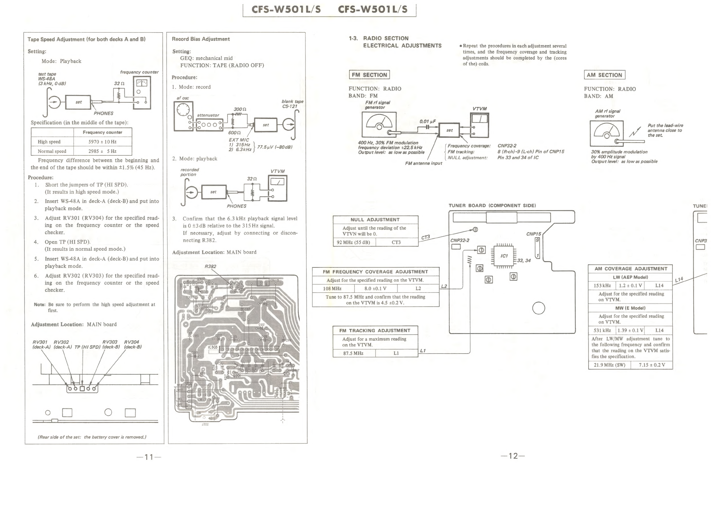
Sony CFS-W501L/S User manual
Other Sony Cassette Player manuals

Sony
Sony Walkman WM-EX615 User manual

Sony
Sony Walkman WM-WE1 User manual

Sony
Sony TCM-400DV User manual

Sony
Sony WM-AF62 User manual

Sony
Sony PVW-2650 User manual

Sony
Sony CFD-E75 Marketing User manual

Sony
Sony WM-GX90 User manual

Sony
Sony Sports Walkman WM-FS499 User manual

Sony
Sony Walkman WM-FX465 User manual

Sony
Sony WM-FS555 - S2 SPORTS WALKMAN User manual

Sony
Sony Walkman WM-EX194 User manual

Sony
Sony Walkman WM-EX162 User manual

Sony
Sony TCM-8EV User manual

Sony
Sony Walkman WM-FX473 User manual

Sony
Sony Walkman WM-FX275 User manual

Sony
Sony TCS TCS-30D User manual

Sony
Sony Walkman WM-EX615 User manual

Sony
Sony TC-W310 User manual

Sony
Sony Walkman WM-FX479 User manual

Sony
Sony CFM-20L User manual