manuals.online logo
Brands
  1. Home
  2. •
  3. Brands
  4. •
  5. Nakamichi
  6. •
  7. Cassette Player
  8. •
  9. Nakamichi CR-2 User manual

Nakamichi CR-2 User manual

Other manuals for CR-2

3

This manual suits for next models

3

Other Nakamichi Cassette Player manuals
Nakamichi CR-7 User manual

Nakamichi

Nakamichi CR-7 User manual

Nakamichi BX-125 User manual

Nakamichi

Nakamichi BX-125 User manual

Nakamichi 1000 User manual

Nakamichi

Nakamichi 1000 User manual

Nakamichi DRAGON User manual

Nakamichi

Nakamichi DRAGON User manual

Nakamichi BX-300 User manual

Nakamichi

Nakamichi BX-300 User manual

Nakamichi CR-2 User manual

Nakamichi

Nakamichi CR-2 User manual

Nakamichi TD-700 User manual

Nakamichi

Nakamichi TD-700 User manual

Nakamichi ZX-7 User manual

Nakamichi

Nakamichi ZX-7 User manual

Nakamichi BX-100 User manual

Nakamichi

Nakamichi BX-100 User manual

Nakamichi DR-1 User manual

Nakamichi

Nakamichi DR-1 User manual

Nakamichi RX-505 User manual

Nakamichi

Nakamichi RX-505 User manual

Nakamichi BX-300 User manual

Nakamichi

Nakamichi BX-300 User manual

Nakamichi MR-1 User manual

Nakamichi

Nakamichi MR-1 User manual
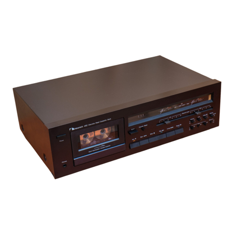
Nakamichi RX-505 User manual

Nakamichi

Nakamichi RX-505 User manual

Nakamichi RX-202E User manual

Nakamichi

Nakamichi RX-202E User manual

Nakamichi CR-4 User manual

Nakamichi

Nakamichi CR-4 User manual

Nakamichi CR-2 User manual

Nakamichi

Nakamichi CR-2 User manual

Nakamichi RX-202E User manual

Nakamichi

Nakamichi RX-202E User manual

Nakamichi 481 User manual

Nakamichi

Nakamichi 481 User manual

Nakamichi CR-3 User manual

Nakamichi

Nakamichi CR-3 User manual

Nakamichi 700ZXL User manual

Nakamichi

Nakamichi 700ZXL User manual

Nakamichi 480 User manual

Nakamichi

Nakamichi 480 User manual

Nakamichi 700ZXE User manual

Nakamichi

Nakamichi 700ZXE User manual

Nakamichi BX-100 User manual

Nakamichi

Nakamichi BX-100 User manual

Popular Cassette Player manuals by other brands

Ahuja CPA-360 Operation manual

Ahuja

Ahuja CPA-360 Operation manual

Sony Pressman TCS-60DV Specifications

Sony

Sony Pressman TCS-60DV Specifications

Philips AQ6485/14 Product information

Philips

Philips AQ6485/14 Product information

Sony TCM-200DV - Cassette Recorder operating instructions

Sony

Sony TCM-200DV - Cassette Recorder operating instructions

Panasonic RQ-E25V operating instructions

Panasonic

Panasonic RQ-E25V operating instructions

Aiwa TP-VS535 operating instructions

Aiwa

Aiwa TP-VS535 operating instructions

Yamaha MT8X Operation manual

Yamaha

Yamaha MT8X Operation manual

Sherwood Newcastle D-480 operating instructions

Sherwood

Sherwood Newcastle D-480 operating instructions

Manta MA408 user manual

Manta

Manta MA408 user manual

GPO W0162B user guide

GPO

GPO W0162B user guide

Marantz CP230 Service manual

Marantz

Marantz CP230 Service manual

Sony HST-471 Service manual

Sony

Sony HST-471 Service manual

Sharp JC-AV1 Operation manual

Sharp

Sharp JC-AV1 Operation manual

Pioneer CT-W103 Service manual

Pioneer

Pioneer CT-W103 Service manual

Sony CFS-B15 - Am/fm Stereo Cassette Recorder operating instructions

Sony

Sony CFS-B15 - Am/fm Stereo Cassette Recorder operating instructions

Sony WMFS220 - Portable Sports AM/FM Cassette... operating instructions

Sony

Sony WMFS220 - Portable Sports AM/FM Cassette... operating instructions

Aiwa HS-TA21 operating instructions

Aiwa

Aiwa HS-TA21 operating instructions

Sanyo MCD-ZX700F Service manual

Sanyo

Sanyo MCD-ZX700F Service manual

manuals.online logo
manuals.online logoBrands
  • About & Mission
  • Contact us
  • Privacy Policy
  • Terms and Conditions

Copyright 2025 Manuals.Online. All Rights Reserved.

Service
Manual
Nakamichi
Nakamichi
CONTENTS
Ne
mo
Se
10.
11.
12.
pe
1.1.
General
6
is2c6%,
Siecearad
oki
tirade
enersed
gabon
eiteus-
ba
Matis
PULA
WRAN
Ge
db
iatateig
doe
Sy
tas
Beat
ldr
hl
cad
Pe
ai
eae
one
the
1
Removal
Procedures
.........
0.002
eee
eeeneceee
acne
sear
Beebe
eto:
ep
CURIS
Br
cso
Maa
be,
Wee
thea
BLE
Soha
WS
3
2
21.
Top
Cover
Ass’y
and
Bottom
Cover
Ass’y
...
0.00.00
0c
ce
eee eee
ee
ee
eee
ee
eae
3
2.
(2.
Cassette.Case:
Cover
ASS’
Ys
joing
p85
a
o-2
Ms
aap
ee)
shield
ac
80.
kG
8
Pada
Hla
Sid
ow
Sdn
Wake
ae
eet
Sa
ee
3
2.
3.
Mechainism:
Ags)
ys.
525
02:
eta
deck
ae
esate
ta,
ohh
ae
Rice
b
yds
Sy
wap
eed
nd
MOPS
Sr
Baa
ate
ee
dW
ck
eecal
dees
hob
ace
Be
3
2.0
A;
Pin
Jack
P.C.B,
Ass’y
and
Main
P.C.B.
Ass’y
2.0...
ee
tee
ee
ee
nee
3
2. 5.
Front:Panel
5520-930
sae
psee:
hana
avis,
ig
ae
dpe
lateiere
Gok
HR
Buelavel
w
FG
RVR
we
Bw
ee
ee
ees
4
2. 6.
Bias
Tune
Volume
P.C.B.
Ass’y
2...
0.
ee
ee
ete
eee
eee
ae
4
25°
Ts
Control:
PC
IBM
Assy.
iccats
Seg
Pid
tase
so
ia
ies
Blea
olay
Oh,
Bae
ee
Oe
Re
RN
ay
al
tos
sca
cee
echo
det
4
2.
8.
Power
Switch
dome:
ais écsc.
soe
ob
aco.
dyer
eile
6
as
ale.
hive
dudes
SB
Gebel
Doteea!
Bote
aA
AS UE
eae
es
ndtias
%
4
est.
Tapes
and
Gauges
«5.0.00
oy
shar
sca
cease.
a
bee
ale
bedee
Ng
See.
Bla
we
Oh
aa
0
Sele
Ca
Bae
a
ed
ween
Weed
ae
ha
a
Ra
5
Mechanical
Adjustments
....
00.00.00
ccc
ee
ee ee
nee eee
eee
eee
ee
ee
enn
ee
eee
nen
5
4.
1.
Tape
Guide
Height
Check
for
Record/Playback
Head
and
Erase
Head
...............000004
5
4,
Head
Base
Stroke
Check
1...
0...
0.
cece
ee
ee
ee
ee
eee
eee
eee
eee
n
nes
5
4.
3
Record/Playback
Head
Azimuth
Alignment
and
Height
Check
.............0.0
0000
eeeeee
5
4,
4
Pressure
Adjustment
of
Pressure
Roller...
0...
ee
eee
ee
eee
eee
6
4,
5
Tape
Pravelling
Chee
225525,
sos
5a,
pide
iets
eid
so
aten
ae
tes
ne
ine
lag
ata
oleh
dae
Se
BO
Ie
te
Als
seemed
daha
Bhat
6
4.
6
Eject
Damper
Adjustment
........
0.0
cc
cc
ee
ee
eee
ew
eee
ee
eee
tet
e
en
ae
6
4.
7
Reel
Motor
Speed
Adjustment
in
Play
Mode
.......0.
0.0.00
eee
ence
ee
eee
eens
6
4,
;
Tape:
Speed:
Adjustment:
i:
3>5-
ste
lactase
d
h8
econo
evel
5,
28e-
erco tae.
Spe
Sat
eh
ends
ane
or
eluate
Soda
adi
weatk
6
4. 9.
TAM
DriC
atin
esd
scien
Setar
ate
feak
ha
Wer
cf
eco
Wal
bee
eteye
wow
a
ae
SVE
edb
a
Ae
WEE
tee
eee
hake
carly
6
Parts
Location
for
Electrical
Adjustment...
0.0.0.0...
2c
ee
ee
ee
eee
een
ee
teen
n
nee
q
Electrical
Adjustments
2.
3
6'o58.5.
0.5.46
sn
Que
Gave
5
cenit
p
Soe
oOo.
ee.
oo
Doar
een,
He
ouy
cortenier.
dear
hard
iw
Ghia!
abehar
ba
he
8
Mechanism
Ass’y
and
Parts
List...
0...
ee
ee
ee
eee
ee
teen
eee
een
n
nee
11
7
1.
DY
NUNSIS:.
4.4
«.
siece
cd
Seitid
GoM
faves
se
at
wore
ahow
hi
WEGR
EE
coe
ausah
re
ravine
alae
eB
MaNMG
Sa
Ba
Berd
Saas
here
aa
d
eA
g
dc
11
7
2,
Chassis:
Ass'y
(A010),
osteo
la
Aah
ecb
ete
Bales
Ga
EE
hou)
olf
enb ane
a
alata
bb
Le
etane
eee
2
12
7
3,
Bottom:
Cover
:Ass’y:
(A02)
icc
isacs.
trig
a
GS
seas
Saw
Bahn
WR
oo
Scale
“eS
a
eee
eke
12
7
4,
Mechanism
‘Ass’y
(B01):
<6.
2-4
¢
66
sees
Seo
ew
ele
ee
blab
oe
RS
oa
ee
a
alae
ek
5
13
7.
6.
Front
Escutcheon
Ass’y
(B02)
2.0...
2...
ec
ee
ee
eee
eee
ee ee
eee
eee
eee
14
Mounting
Diagrams
and
Parts
List
..
2.0.0...
2.
ec
ee
ee
eee
ee
ee
eee
ee
nn
eee
ane
eae
15
8
1.
Buge’P.C:B:
Assy
42:0
5.
shen
o5Syalerwcte
hae
aiecy
nce
se
We
tucenee
Wak
Bia
Gd,
OE Wa
ble
eo
aena
ete
ws
15
8.
2.
Pitt.
dack:
P.C.
Bz
Ass?¥.
23.05
set
ee
6
ge
ete
es
wd
Se
bee
0S
Oe
Sk
0
be
ata
eee
Se
Ee
ae
el
lacs
15
8.
3.
Input
Volume
P.C.B,
Ass’y
2...
0.
cc
eee
et
eee
eee
eee
nae
15
8
4
Output:
Volume’
P;C.B,
Ass’
Yo
55
96s
d
Sie
eg
ere,
8
New
Ga
voces
lee
adda
ae
Wn
Rod
ae
as
16
8.
5
Headphone
P.C.B.
Ass’y.
1...
ce
ee
ee
eee
ee
eee
eee
ere eee
eeeeeeenes
16
8.
6.
Bias
Tune
Volume
P.C.B,
Ass’y
1.
ee
eee
eee
ee
eee
eee
eee
ene
ee
16
82
1%
~Shutoft
PC
Bu
Ass
y's
g:cce-pat
ait
lee
a
deca
ee
Gas
Bete
a
ght
Seared
even:
acted
bak
eat
iia
hte.
a
lath
16
8.
8
Control
P-C-Bs
Ass’y
2
fen
K
tires
tie
koe
teen
eh
elt
Be
wend
dtd
dace
i
Seativin,
ae
OS
ee
es
ee
16
8
9.
Main.
PC)
B.
Ass’¥"
icine
dt
e7n
Sat
94,
ae
tyes
ott
ls
eco
ec
dha
Ee
aoe
Sone
LS
&
ae
eee
ve de
ise
dda
BH
be
17
Schematic:
Diagram...
«0.3.5.
d05
6b
Ach
ae
we
Rae
ek
Reno
ep
ee
een
8%
Abdel
eG
Ios
wae
idces
Be)
we
el
bee
19
ee
IC:
Block:
Diagrams!
onicti
2.234,
sh50
0
-aeidis
Sod
A
havaicds
dea
ele
ecw Bed
Peet
dws
oho
NS
ee ae
hw
ws
Geel
19
9o5
2;
Schematic:
Diagrann:
os.
p5
eee
otha.
ee
crite
asa
ina
Mahea
No,
oy
ib
bend
dn
gar
a
ween
lb
dab
beled
SOE
wth
dence
a
24
Wiring:
Diagram
ios.
ioe
escwa
olen
fee
oe
ebb
be
See
een
else
ace
wale
ow
APS
ob
glenda
Ties
Ba
ater
ose
Bieacdh
wy
abudlades
a
ghe
25
Block
Diagrams.
o-.5
isc.
eidie
oe
eae
oe
Fe
ee
oe
Re
ww
ale
Sedu
os
ade
ea
wet
eee
Vie
alee
gw
ea
Boers
ele
bua ose
26
1
oo.
Amplifier.
Section’
caine
ko
ted
hs
eek
ada
ek
ese
Ew!
aM
en
eR
Pa
Rte:
en
ta
be
UL
ge
te
Be
bee
eae
aw
26
11.
2.
Mechanism
Control
Section
.
2...
0...
0c
ee
ee
ee
eee
eet
ee
eee
eee
27
Timing
Charts
and
Eq.
Amp.
Frequency
Response
...........0.0
0c
cece
ee
eee
nee
ee
eee
ne
renee
28
12.
#1.
“Timing
Charts
®
j.2.0,:0%5
asc:
abou
te
lg
ooeta
SR
eh eb
we
ale
oe
Goa
eerns
W
elswa
eed
aed
4
Macken
bebe
Sides
28
12.
2.
Eq.
Amp.
Frequency
Response
..........0.0
00
ccc
ee
ne
ee
eee
eens
29
SDECHICATIONS:
|
5.4).55.56
ete.
Bidet
ered
co
Weg
Saw
acs
dy
oa
ete
on
By
oqec
Ble’
de
APD
a
0,
Bee
pea
we
eel
eter
oad
be
ot
380
GENERAL
Voltage
Selector
Voltage
selector
is
installed
on
the
rear
panel
for
Other
version
of
the
Nakamichi
CR-2.
This
voitage
selector
can
select
110,
127,
220,
or
240
V
at
customer’s
disposal.
1.2.
Schematic
Ref.
No,
Part
No.
Package
Ass*y
and
Accessory
Ass’y
Description
Fig.
1
Schematic
Ref.
No.
Description
01
OF04070A
OF04071A
OF
04072A
OF04100A
02
OF
04087C
03
OF
04088C
04
OF03684A
0D04046A
0D04047A
OM03457A
OM05101A
OM05070A
0OM05054A
OM05087A
OM05106A
OM05105A
OM05107A
OM05108A
0M05102A
0M05103A
Package
Ass’y
Carton
Box
(CR-2)
Caxton
Box
(CR-2A)
Carton
Box
(CR-2E)
Carton
Box
(CR-20)
Packing
L
Packing
R
Poly-Sheet
S
Warranty
Card
(CR-20)
User’s
Pack
(CR-20)
Voltage
Label
240V
(CR-2
(Australia)
&
CR
2E
(UK))
Voltage
Label
(CR-2
(Saudi
Arabia))
Serial
No,
Label
(CR-2A)
Serial
No.
Label
(CR-2,
CR-2E
&
CR-20)
Point
of
Sale
Label
(CR-20)
UL
Label
(CR-2A)
LA
Label
(CR-2A)
Canada
Label
(CR-2A)
UL/Canada
Label
(CR-2A)
Shipping
Label
Los
(CR-2A)
Shipping
Label
VAN
(CR-2A)
BRE
REE
BN
N
NEBR
RRR
eRe
Oe
0D03092B
0D04449A
0D04810A
O0D04766A
0D04780B
0D04781B
0D04785B
OD04796A
OD04795A
ODO04797A
0D04812A
0M03844B
DA04121A
Accessory
Ass’y
Poly-Bag
Important
Notice
(CR-2,
CR-2E
&
CR-20)
Important
Notice
(CR-2A)
General
Catalogue
(CR-2A)
Owner’s
Manual
(English/
German/French)
Owner’s
Manual
(Japanese)
Price
Card
(CR-20)
Tape
Catalogue
(CR-2A)
Tape
Catalogue
(CR-20)
Warranty
Card
(CR-2A)
Tape
Supplement
Power
Cord
Label
(CR-2E
(UK))
Pin
Cord
Ass’y
ee
Rte
Ft
fed
bd et
ee
2.
REMOVAL
PROCEDURES
2.1.
Top
Cover
Ass’y
and
Bottom
Cover
Ass’y
Refer
to
Fig.
2.1.
(1)
Loosen
FO1
and
remove
F02
(Top
Cover
Ass’y).
(2)
Loosen
F03
and
remove
F04
(Bottom
Cover
Ass’y).
2.2.
Fig.
2.1
Cassette
Case
Cover
Ass’y
Refer
to
Fig,
2,2,
ql)
(2)
Press
FO1
(Eject
Button)
to
open
FOQ2
(Cassette
Case
Cover
Ass’y).
Pull
FO2
(Cassette
Case
Cover
Ass’y)
upward,
Fig,
2.2
2.3.
Mechanism
Ass*y
Refer
to
Fig.
2.3.
ql)
(2)
(3)
Remove
the
Top
Cover
Ass’y
and
the
Bottom
Cover
Ass’y
referring
to
item
2.1.
Remove
the
Cassette
Case
Cover
Ass’y
referring
to
item
2.2.
Loosen
FO1
and
FO2,
remove
FO3,
and
disassemble
F04
(Mechanism
Ass’y).
Fig.
2.3
2.4,
Pin
Jack
P.C.B.
Ass’y
and
Main
P.C.B.
Ass’y
Refer
to
Fig.
2.4.
(1)
Remove
the
Top
Cover
Ass’y
and
the
Bottom
Cover
Ass’y
referring
to
item
2,1.
(2)
Loosen
FO1
and
remove
FO2
(Pin
Jack
P.C.B.
Ass’y).
(3)
Loosen
F083
and
FO4,
and
lift
FO5
(Main
P.C.B.
Ass’y).
Note:
When
installing
the
Main
P.C.B.
Ass’y,
to
facilitate
installation,
place
the
Main
P.C.B.
Ass’y
so
that
the
tops
of
switches
on
the
Main
P.C.B.
Ass’y
come
in
contact
with
the
ends
of
push
buttons
as
shown
in
Fig,
2.5.
Fig.
2.4
Fig.
2.5
2.5.
Front
Panel
2.7,
Control
P.C.B.
Ass’y
Refer
to
Fig.
2.6.
Refer
to
Fig.
2.8.
(1)
Remove
the
Top
Cover
Ass’y
and
the
Bottom
Cover
Ass’y
(1)
Remove
the
Top
Cover
Ass’y
and
the
Bottom
Cover
Ass’y
referring
to
item
2.1.
referring
to
item
2.1.
(2)
Remove
the
Cassette
Case
Cover
Ass’y
referring
to
item
2.2.
(2)
Remove
the
Mechanism
Ass’y
referring
to
item
2.3.
(3)
Pull
out
FO1,
FO2
and
FO3,
and
loosen
F04
and
F05,
(3)
Remove
the
Front
Panel
referring
to
item
2,5,
(4)
With
pushing
claws
by
hand
as
shown
in
the
figure,
remove
(4)
Loosen
FO1
and
F0O2
with
a
special
nut
driver
or
with
pliers
F06
(Front
Panel).
(5)
to
set
FO3
(Bias
Tune
Volume
P.C.B.
Ass’y)
free.
With
pushing
FO3
(Bias
Tune
Volume
P.C.B.
Ass’y)
in
the
direction
of
the
arrow,
loosen
F04,
unhook
F05,
and
remove
FO6
(Control
P.C.B.
Ass’y).
Fig.
2.8
2.6.
Bias
Tune
Volume
P.C.B,
Ass’y
2.8.
Power
Switch
Joint
Refer
to
Fig,
2.7,
Refer
to
Fig,
2,9.
(1)
Remove
the
Top
Cover
Ass’y
and
the
Bottom
Cover
Ass’y
(1)
Remove
the
Top
Cover
Ass’y
referring
to
item
2,1,
referring
to
item
2.1.
(2)
Pull
FO1
(Power
Switch
Joint)
upward
to
remove
it,
(2)
Remove
the
Main
P.C.B.
Ass’y
referring
to
item
2.4,
(3)
Remove
the
Front
Panel
referring
to
item
2.5.
(4)
Loosen
FO1
and
F02
with
a
special
nut
driver
or
with
pliers,
and
remove
F03
(Bias
Tune
Volume
P.C.B.
Ass’y).
Main
PC.8.Assy
Fig.
2.9
3.
TEST
TAPES
AND
GAUGES
(1)
400
Hz
Level
Tape
(DA09005B)
(2)
1kHz
Track
Alignment
Tape
(DA09007B)
(3)
10kHz
PB
Frequency
Response
Tape
(DA09003B)
(4)
15
kHz
PB
Frequency
Response
Tape
(DA09002B)
(5)
20
kHz
PB
Frequency
Response
Tape
(DA09001B)
(6)
15
kHz
Azimuth
Tape
(DA09004B)
(7)
3kHz
Speed
and
Wow/Flutter
Tape
(DA09006C)
(8)
Tape
Travelling
Cassette
(DA09071A)
(9)
Reference
EXII
Tape
(DA09111A)
(10)
Reference
SX
Tape
(DA09110A)
(11)
Reference
ZX
Tape
(DA09109A)
(12)
Head
Alignment
Gauge
(DA09092B)
(13)
Torque
Gauge
FWD
(DA09082A)
4,
MECHANICAL
ADJUSTMENTS
4.1.
Tape
Guide
Height
Check
for
Record/Playback
Head
and
Erase
Head
With
use
of
a
Head
Alignment
Gauge
(DA09092B),
tape
guide
height
check
for
the
Record/Playback
and
Erase
Heads
shall
be
made,
wherein
a
small
block
shall
be
pushed
straight
down
to
the
base
while
in
use
of
the
Head
Alignment
Gauge
(DA09092B),
Refer
to
Fig.
4,1.
(1)
Record/Playback
Head
Tape
Guide
Height
(a)
Load
the
base
of
the
Head
Alignment
Gauge
(DA09092B)
carefully
and
set
the
cassette
deck
in
Play
mode,
(b)
Piace
the
small
block
of
the
Head
Alignment
Gauge
(DAO-
9092B)
on
the
base,
:
(ec)
Slide
the
smali
block
against
the
tape
guide
of
the
Record/
Playback
Head,
and
check
to
insure
that
the
block
is
accepted
by
the
tape
guide,
(a)
If
not,
loosen
the
screw
and
insert
a
shim
(either
30
um
(0C80048A),
60
wm
(0C80038A),
or
100
um
(0C80039A))
to
raise
the
Record/Playback
Head,
then
tighten
and
apply
a
quantity
of
lock
tight
paint
to
the
screw.
(2)
Erase
Head
Tape
Guide
Height
(a)
Load
the
base
of
the
Head
Alignment
Gauge
(DA09092B)
carefully
and
set
the
cassette
deck
in
Play
mode,
(b)
Place
the
small
block
of
the
Head
Alignment
Gauge
(DA09092B)
on
the
base.
(c)
Slide
the
small
block
against
the
tape
guide
of
the
Erase
Head,
and
check
whether
the
block
is
accepted
by
the
tape
guide,
4.2.
Head
Base
Stroke
Check
Refer
to
Fig.
4.2.
(1)
Load
the
base
of
the
Head
Alignment
Gauge
(DA09092B)
carefully,
then
push
the
base
toward
the
Record/Playback
Head
to
eliminate
the
clearance
between
the
reference
pin
and
the
base,
(2)
Setthe
cassette
deck
in
Play
mode,
(3)
Piace
the
small
block
of
the
Head
Alignment
Gauge
(DAO-
9092B)
on
the
base.
(4)
Contact
the
small
block
with
the
Record/Playback
Head
surface
and
the
Erase
Head
surface,
and
check
whether
the
end
of
the
small
block
is
located
within
the
specified
toler-
ance
as
shown
in
Fig.
4.2.
4.3.
Record/Playback
Head
Azimuth
Alignment
and
Height
Check
Refer
to
Fig.
4.1.
(1)
Contact
an
AC
voltmeter
to
the
Output
Jacks.
(2)
Load
a
15
kHz
Azimuth
Tape
(DA09004B)
and
set
the
cassette
deck
in
Play
mode,
(3)
Tur
the
Azimuth
Alignment
Screw
until
the
outputs
of
both
channels
become
maximum.
(4)
Load
a
1
kHz
Track
Alignment
Tape
(DA09007B)
and
set
the
cassette
deck
in
Play
mode.
(5)
Check
to
insure
that
the
readings
of
both
channels
on
the
AC
voltmeter
are
below
—25
dB.
If
not,
replacement
of
the
Record/Playback
Head
will
be
required.
(6)
Apply
a
quantity
of
lock
tight
paint
to
the
Azimuth
Align-
ment
Screw.
Alignment
Alignment
Gauge
Gauge
4.4.
Pressure
Adjustment
of
Pressure
Roller
Refer
to
Fig.
4.3,
(1)
In
Play
mode,
measure
the
torque
of
the
Pressure
Roller
and
check
whether
the
torque
is
in
a
range
of
320
+50
g-cm,
(2)
If
torque
is
out
of
the
range,
correct
it
by
changing
the
instal-
lation
point
of
the
Pressure
Rolier
Spring.
4.5,
Tape
Travelling
Check
Load
a
Tape
Travelling
Cassette
(DA09071A)
and
set
the
cassette
deck
in
Play
mode
to
check
the
followings:
(1)
After
more
than
2
seconds,
the
fluctuation
of
the
tape
travel-
ling
on
the
Record
/Playback
Head
is
small,
(2)
Tape
isin
contact
with
the
head
sufficiently.
(3)
Tape
waving
is
small
on
the
heads
and
pressure
roller.
4.6.
Eject
Damper
Adjustment
Refer
to
Fig,
4.4.
Load
a
cassette
tape,
and
with
opening
the
Cassette
Case
by
pressing
the
Eject
button
and
closing
it
by
hand,
adjust
the
speed
of
damper
action
by
the
Damper
Adjustment
Screw,
CCW:
Damper
moves
fast,
CW:
Damper
moves
slowly.
4.7,
Reel
Motor
Speed
Adjustment
in
Play
Mode
(1)
Load
a
Torque
Gauge
FWD
(DA09082A)
and
set
the
cassette
deck
in
Play
mode.
(2)
After
5
to
10
seconds,
adjust
VR601
on
the
Main
P.C.B.
Ass’y
to
obtain
exactly
45
g-cm
on
the
torque
gauge,
4.8.
Tape
Speed
Adjustment
Refer
to
Fig,
4.5.
(1)
Connect
a
frequency
counter
to
the
Output
Jacks,
(2)
Load
a8
kHz
Speed
and
Wow/Flutter
Tape
(DA09006C)
and
play
it
back,
(3)
Adjust
the
Tape
Speed
Adjustment
Volume
incorporated
in
the
Capstan
Motor
to
obtain
3,000
Hz
on
the
frequency
couter,
CCW:
Motor
drives
slowly.
CW:
Motor
drives
fast.
4.9.
Lubrication
The
tape
transport
is
of
a
lubrication-free
type
mechanism,
When
the
following
parts
are
replaced,
apply
the
specified
lubricant,
(1)
Molykote
(R)
Grease
(X5-6020)
Cam
Motor
Pulley
Thrust
portion
on
the
Capstan
Shaft
(2)
FLOIL
GB-TS-1
Washer
between
Reel
Hub
Ass’y
and
Back
Tension
Spring
(3)
Diamond
Oil
(EP-56)
Reel
Hub
Shaft
(4)
Anderol
456
Capstan
Shaft
Note:
We
suggest
that
you
use
the
above
specified
lubricant
or
equivalent
type.
The
company
dealing
in
the
above
lubricant
is
as
follows:
(a)
Molykote
(R)
Grease
(X5-6020)
Dowcorning
Co.,
Ltd.,
1-15-1
Nishishinbashi,
Minato-
ku,
Tokyo,
Japan
(b)
FLOIL
GB-TS-1
Kanto
Chemicals
Co.,
Ltd.,
2-7
Kanda
Sakuma-cho,
Chiyoda-ku,
Tokyo,
Japan
(c)
Diamond
Oil
(EP-56)
Mitsubishi
Oil
Co.,
Ltd.,
1-2-4
Toranomon,
Minato-ku,
Tokyo,
Japan
(d)
Anderol
456
Toyo
Kokusai
Oil
Co.,
Ltd.,
3-3-5
Hatchobori,
Chuo-
ku,
Tokyo,
Japan
Fig.
4.3
Increase
Damper
Adjustment
Screw
Decrease
N
Increase
Capstan
Motor
on
Fig.
4.5
PARTS
LOCATION
FOR
ELECTRICAL
ADJUSTMENT
5.
?
GNS
z
©
4
QOHYA
(a)
3()
3
[1@]
cl
x2
—
vo
ray
=
G|
gozuA
XS
-——F
(ZHHOZ)
[8487
YODGADId
@
|
Aouanbas4
9S0
spIg
G|
60zuA
X3-——
rOEL
|
9024uA
ia)
G|
mae
XxZ—4
[a]
[a]
s0zdl
©
G@|
BOLYA
XS
ss)
os
®
[2]
(|
|
oie
G|
60I¥A
X3———S0IG
e027
¢€0r
43bi!4
XdW
doal
sepsiv
=|
juan
asol3
@)
pOEYNA
1d
d
uloW
@
id
ZOLA
ZOZUA
|
ssn
sell
(ZHOOP)
€OZUA
HOZYA
GOZBA
eae
(@a\@)
"y9°98y
EQOA
POLYA
SOYA
@|
[9a
lOZYA
FOLUA
(Kd]q)
paads
s0,0W
122y
(a)
[eAe7y
1a;3aW
HOSYA
Fig.
5
6.
ELECTRICAL
ADJUSTMENTS
Set
the
CR-2/2A/2E/20
as
shown
in
MODE.
Balance
-
Center
Bias
Tune
—
Center
Eq.
-
70
us
Tape
-
ZX
MPX
Filter
-
OFF
Dolby
NR
-
OFF
Playback
1.
Play
back
a
Torque
Gauge
FWD,
and
after
5
to
10
seconds,
adjust
VR601
to
obtain
44
+
1
g-cm
on
the
Torque
Gauge
at
25
degrees
(45
+
1
g-cm
at
20
degrees).
2.
Check
that
the
deviation
of
the
torque
value
is
within
+10
g-cm
of
the
center
value.
Note:
Torque
adjustment
must
be
done
after
leaving
the
CR-2/2A/2E/20
for
one
hour
with
the
power
switch
turned
OFF.
Reel
Motor
Speed
Adjustment
(Play)
Gauge
FWD
(DA09082A)
Tape
Speed
Frequency
|
Playback
Tape
Adjust
the
volume
incorporated
in
the
Adjustment
|Speed
Counter
to]
Eq.
-
70
ps
Speed
capstan
motor
to
obtain
3
kHz
+15
Hz
on
and
Wow/
Output
Adj.
the
frequency
counter,
Flutter
Jacks
Volume
Tape
(Capstan
(DA09006C)
Motor)
Record,
Pause
1.
Feed
in
400
Hz
and
adjust
the
Input
Level
control
to
obtain
500
mV
-1.2
dB
on
the
AC
voltmeter.
2.
Adjust
VR101
(VR201)
so
that
the
0
dB
segment
of
the
level
meter
starts
illuminating.
Meter
Level
Calibration
Record,
Pause
MPX
-
OFF/ON
MPX
Filter
Adjustment
1.
Adjust
the
Input
Level
control
to
obtain
500
mV
(0
dB)
on
the
AC
voltmeter.
2.
Set
the
MPX
Filter switch
to
ON
and
adjust
L101
(L201)
to
obtain
minimum
reading
on
the
AC
voltmeter
(minimum
reading
will
be
less
than
-30
dB).
Record/
15
kHz
AC
Volt-
Playback
Record/
|Adjust
the
Record/Playback
Head
Azimuth
Playback
Azimuth
meter
to
Eq.
-
70
ps
Playback|Alignment
Screw
to
obtain
maximum
Head
Tape
Output
Dolby
NR
-
Head
readings
for
both
channels
on
the
AC
Azimuth
(DA09004B)
|
Jacks
OFF
Azimuth
jvoltmeter.
Alignment
MPX
~-
OFF
Align-
ment
Screw
Playback
400
Hz
AC
Volt-
Same
as
Adjust
VR102
(VR202)
to
obtain
500
mV
on
Level
Level
Tape|meter
to
above
the
AC
voltmeter,
7
Jacks
Calibration]
(DA09005B)
|
Output
Playback
Frequency
Response
Adjustment
Bias
Oscillation
Frequency
and
Erase
Current
Adjustment
Level
Tape/meter
to
(DA09005B)
|
Output
10
kHz
PB
|Jacks
Frequency
Response
Tape
(DA09003B)
15
kHz
PB
Frequency
Response
Tape
(DA090028B)
20
kHz
PB
Frequency
Response
Tape
(DA090018B)
Frequency
Counter
between’
terminals
1
and
2
of
CN2
on
Main
P.C.B.
across
the
additional
0.1
ohm
resistor
None
AC
Volt-
Playback
Eq.
-
70
ps
Dolby
NR
-
OFF
MPX
-
OFF
Record,
Pause
|
Main
Eq.
-
70
ps
Tape
ZX
Dolby
NR
-
OFF
MPX
-
OFF
1.
Load
a
400
Hz
level
tape,
play
it
back,
and
read
the
playback
level.
Load
10
kHz,
15
kHz
and
20
kHz
PB
frequency
response
tapes
and
play
them
back.
Adjust
the
record/play-
back head
azimuth
to
obtain
maximum
readings
for
both
channels
on
the
AC
voltmeter
with
each
tape.
Check
that
the
playback
levels
are
as
follows
with
respect
to
the
level
for
400
Hz
level
tape.
10
kHz:
-20
dB
-2
to
+2
dB
15
kHz:
-20
dB
-2
to
+3
dB
20
kHz:
-20
dB
-2
to
+4
dB
If
the
level
at
20
kHz
is
out
of
the
range,
adjust
VR106
(VR206)
to
obtain
satisfactory
results.
VR106
(VR206)
compensates
the
playback
frequency
response
at
20
kHz
as
shown
below:
|
Approx.
5d8
10K
20K
Conduct
step
6
"Record/Playback
Head
Azimuth
Alignment",
Connect
an
additional
0.1
ohm
resistor
in
series
to
the
Erase
Head
and
connect
the
AC
voltmeter
across
it,
Adjust
T301
to
obtain
105
kHz
+1
kHz
on
the
frequency
counter.
If
bias
oscillation
frequency
is
above
106
kHz,
short-circuit
C317
and
C318,
and
re-adjust
T301
again.
Adjust
VR304
to
obtain
17.5
mV
(175
mA)
on
the
AC
voltmeter.
(16.5
+
1
mV
(165
+
10
mA
will
be
accepted.)
After
completion
of
the
erase
current
adjustment,
re-check
the
bias
oscillation
frequency.
Remove
the
additional
0.1
ohm
resistor.
Bias
Trap
Adjustment
(Record
Amp.)
Adjust
L103
(L203)
to
obtain
minimum
(remove
meter
to
reading
on
the
AC
voltmeter.
input
TP101,TP201
signals)
on
Main
P.C.B.