Nakanishi Sonic Cutter ZERO User manual


21
English
Thank you for your purchase of Sonic Cutter ZERO Ultrasonic Cutter. This product is a device that
can be used for cutting and deburring of plastic materials, rubber, urethane, etc. as well as for cutting
sheets, cloths, etc. Please read this manual carefully before use. We hope you will enjoy using this
product for many years to come. Please keep this manual in a place where the user can read or refer
to it at all times.
CONTENTS
1. Safety precautions ........................................... 22
2. Product information ......................................... 25
2–1 Bundled items ................................................25
2–2 Names of parts ...............................................26
3. Preparation before use .................................... 29
3–1 Connecting the main power cord ...........................29
3–2 Connecting the handpiece ..................................29
3–3 Connecting the foot switch (optional) ......................29
3–4 Replacing the blade .........................................30
4. How to use .......................................................31
5. Maintenance ................................................... 32
5–1 Fuse replacement ............................................32
5–2 Care ...........................................................32
6. Setup .............................................................. 33
6–1 User setting operations ......................................33
6–2 Setting the forced stop time when not in use .............34
6–3 Setting the notification volume .............................34
6–4 Setting the watt display and amplitude display ............34
6–5 Setting the foot switch ......................................35
6–6 Setting the handpiece heat protection function ...........35
6–7 Initializing Settings ...........................................35
7. Troubleshooting ............................................... 36
7–1 Error code ................................................................. 36
7–2 Failure causes and countermeasures ......................37
8. After sales service ........................................... 39
8–1 Warranty ......................................................39
8–2 Contact for inquiries .........................................39
8–3 Product disposal .............................................39
9. Specifications ................................................. 40
9–1 Specifications ............................................................ 40
9–2 Conforming standards .......................................40
9–3 Protection sircuitry ...........................................41
9–4 Symbol ..................................................................... 41

22
1 Safety Precautions
Please read the operation manual thoroughly, make sure you understand all warnings and cautions prior to operating
the system and only use the system in the manner intended.
These warnings and cautions are intended to avoid potential hazards that could result in personal injury or damage to
the device. These are classified as follows in accordance with the seriousness of the risk.
Class Degree of Risk
WARNING A hazard that could result in bodily injury or damage to the device if the safety
instructions are not properly followed.
CAUTION A hazard that could result in light or moderate bodily injury or damage to the
device if the safety instructions are not followed.
NOTICE Keep this manual in a safe place for future reference.
ŠGROUNDING INSTRUCTIONS
ƔIn the event of a malfunction or breakdown, grounding provides a path of least resistance for electric current to
reduce the risk of electric shock. This tool is equipped with a power cord having an equipment grounding conductor
and a grounding plug. The plug must be plugged into a matching outlet that is properly installed and grounded in
accordance with all local codes and ordinances.
ƔDo not modify the plug provided-if it will not fit the outlet, have the proper outlet installed by a qualified electrician.
ƔImproper connection of the equipment-grounding conductor can result in a risk of electric shock. The conductor with
insulation having an outer surface that is green with or without yellow stripes is the equipment grounding conductor.
If repair or replacement of the power cord or plug is necessary, do not connect the equipment-grounding conductor
to a live terminal.
ƔCheck with a qualified electrician or service personnel if the grounding instructions are not completely understood, or
if in doubt as to whether the tool is properly grounded.
ƔUse only 3-wire extension cords that have 3-prong grounding plugs and 3-pole receptacles that accept the tool's
plug.
Ɣ(120V) This tool is intended for use on a circuit that has an outlet that looks like the one illustrated in Sketch A in
Figure (below). The tool has a grounding plug that looks like the plug illustrated in Sketch A in Figure (below). A
temporary adapter, which looks like the adapter illustrated in Sketches B and C, may be used to connect this plug to
a 2-pole receptacle as shown in Sketch B if a properly grounded outlet is not available. The temporary adapter should
be used only until a properly grounded outlet can be installed by a qualified electrician. The green-colored rigid ear,
lug, and the like, extending from the adapter must be connected to a permanent ground such as a properly grounded
outlet box.
Ɣ(240V) This tool is intended for use on a circuit that has an outlet that looks like the one illustrated in sketch D in
figure.
ƔNOTE: Adapter in (Figure B) is not for use in Canada.
GROUNDING
PIN GROUNDING
CONTACT
METAL
SCREW
(A)
COVER OF GROUND
OUTLET BOX
(B)
(C)
(D)
ADAPTER
GROUNDING
MEANS
ƔUse proper extension cord. Make sure your extension cord is in good condition. When using an extension cord, be
sure to use one heavy enough to carry the current your product will draw. An undersized cord will cause a drop in line
voltage resulting in loss of power and overheating. Table (below) indicates the correct size to use depending on cord
length and nameplate ampere rating. If in doubt, use the next heavier gauge. The smaller the gauge number, the
heavier the cord.

23
Safety Precautions
English
Ampere Rating Volts Total length of cord
120V
240V 7.5m (25ft.)
15m (50ft.) 15m (50ft.)
30m (100ft.) 30m (100ft.)
60m (200ft.) 45m (150ft.)
90m (300ft.)
More Than Not More
Than
0 6 18 16 16 14
6 10 18161412
10 12 16 16 14 12
12 16 14 12 Not Recommended
Use the table above for your correct voltage.
WARNING
ƔFor safety reasons, always wear protective gloves and goggles when using this product.
ƔDo not drop or impact the product. Strong impacts may result in deformation or damage.
ƔDo not modify or disassemble this product in any way that is not described in the instruction manual. This can
have a significant impact on performance and safety. If the controller is disassembled, you may receive an
electric shock due to the high voltage section inside. In the event of malfunction or repair, please contact the
place of purchase for repair.
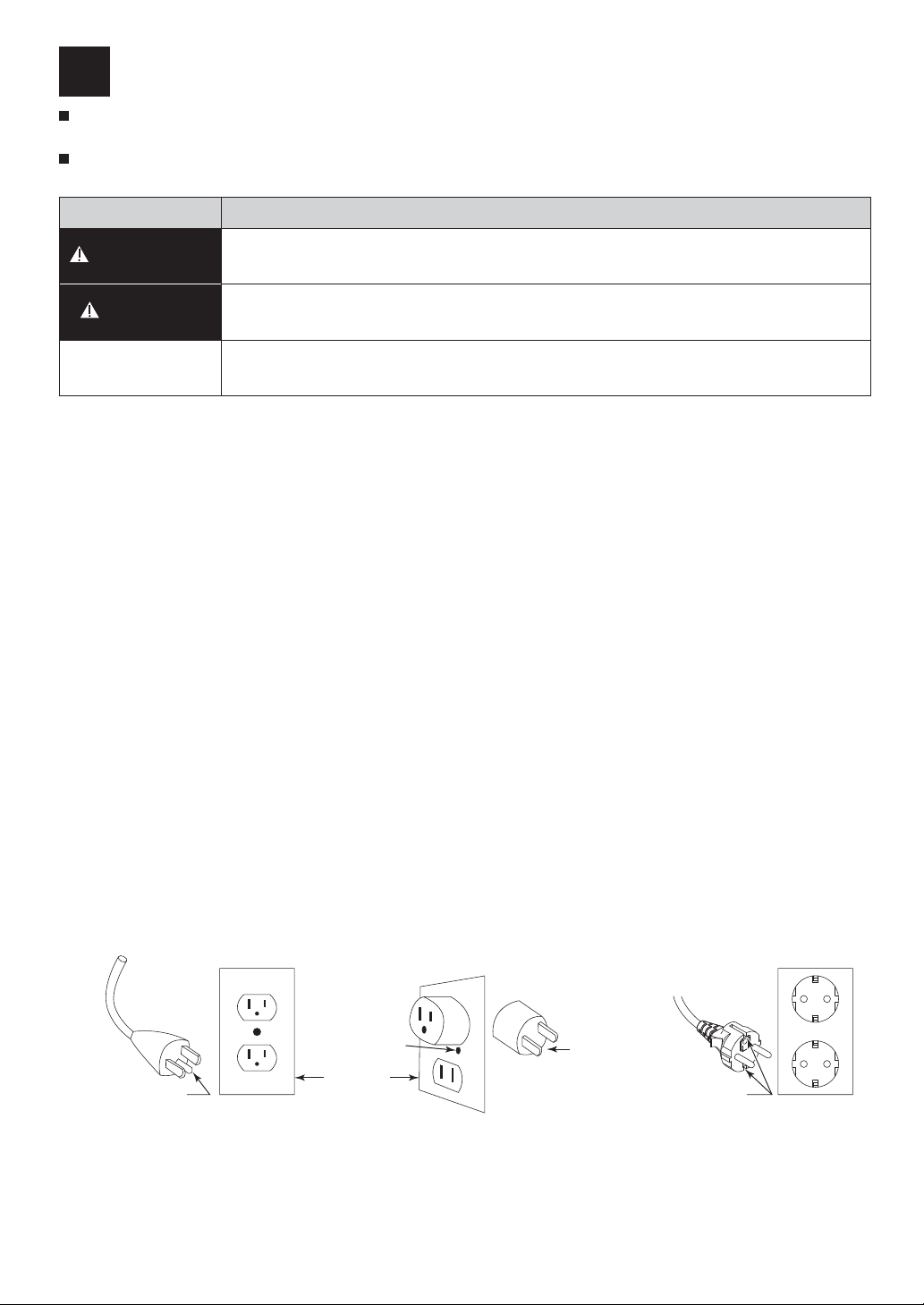
ƔBe sure to ground the grounding wire of the power cord before use. Failure to do so may result in a malfunction,
fire or electric shock.
ƔDo not use this product in an unventilated room where there is a risk of explosion or near flammable materials. If
the tool is in contact with flammable materials for a long periods of time in an oscillating state, it may ignite.
ƔUse the controller at room temperature in the range of 10 - 40°C (75 - 104ºF), with no condensation.
Condensation may cause a short circuit or an electric shock.
ƔAvoid installing the controller in the vicinity of high temperature, high humidity, condensation, corrosive or
explosive gases, flammable gases, salt damage, and direct sunlight. Failure to do so may result in a malfunction,
fire or electric shock.
ƔThe bottom of the controller also serves as a heat sink. Install it so that the space between it and the work desk
is not blocked. A temperature increase can occur inside the controller, causing failure.
ƔIf there is any dust or damage to the threaded part of the blade holder, handpiece, or blade mountings, normal
oscillation will not be possible. It can also cause the handpiece to heat up. In addition,the handpiece maygenerate
heat,so be sure to remove any dust before use.
ƔMake sure the blade is securely installed. If it is not secured firmly, it will cause a loss of power and heat in the
handpiece.
ƔDo not touch the blade or horn during ultrasonic vibration or immediately after the output stops. The blade and
horn parts may become hot and may cause injury or burns.
ƔIf oil or other contaminants get into the handpiece, it may cause a malfunction. Do not lubricate the handpiece.
ƔDamaged main power cord must be replaced with new cord as they may cause fires or electric shock due to a
short circuit. Please contact us or your local distributor for details.
ƔWhen shipped, the handpiece comes with a blade attached. Remove the cap to avoid touching the blade and
causing injury.
ƔIf the blade is over-tightened or cracked, turning the ON / OFF key to "ON" may cause the blade to break off and
fall out oftheholder.

24
Safety Precautions
CAUTION
ƔThe operating environment for this product is 10 - 40°C (75 - 104ºF),, humidity is 30 - 75% RH,, and air
pressure is 700 - 1,060 hPa. Also, use the controller in a non-condensing environment. If used beyond this
range, it may cause malfunctions or damage.
ƔStore the product in a place where the temperature is between 10 - 50°C, degrees Celsius, the humidity is
between 30 - 75% RH, the air pressure is between 500 and 1,060 hPa, and there is no dust, sulfur or salt air.
ƔWhen installing the controller, provide a space of 10 cm behind the controller to allow for smooth insertion and
removal of the power cord in the event of an emergency.
ƔBefore starting to use the product, please inspect it in advance and make sure that there is nothing wrong. If you
notice any abnormality, contact your dealer for repair.
ƔIf the blade or handpiece becomes hot or if a strange noise occurs suddenly during use, stop using it immediately
and check the entire system. If the blade is damaged, do not continue to use it. Replace the blade with a new
one.
ƔBefore turning on the Main power switch or the controller's ON / OFF key (foot switch), make sure that nothing is
in contact with the tip of the handpiece or the blade. Oscillation can be difficult to start if there iscontact. Re-
cuting in the middle of a cut may not be possible if material is stuck to the blade.
ƔIf you hear an abnormal noise coming from the tip of the handpiece, the blade may be broken in the groove at the
tip of the horn, or it may not be installed properly.
ƔDo not turn the ON / OFF key (foot switch) to "ON" with the cap on the handpiece tip.
ƔIf the blade breaks right off at the base after replacing it, the replacement blade may not be correctly installed.
Check the replacement blade for burrs, and replace it witha new blade. Do not use blades with holes inthem.
NOTICE
ƔThis product uses an ultrasonic oscillator. The proximity of computers and LAN cables may affect them. Also, if
there is a radio receiver nearby, there may be noise.
ƔWhen in use, if the operation sounds peculiar to ultrasonic vibration is generated. We recommend that you wear
earplugs.
ƔSet the power switch to OFF after use. Also, unplug the power cord when not in use for long periods of time.
ƔThe user is responsible for operation and maintenance.

25
English
2 Product Information
2–1 Bundled items
After opening the package, please check that the contents of "Table - 1 List of Contents " are inorder.
In the unlikely event that any of the contents of the package are inadequate, please contact " 8–2
Contact for inquiries " or the dealer from whom you purchased the product.
Table - 1 List of Contents
No. Name Code No. Quantity Note
Main power cord - 1 2m
Controller 7785 (120V) 1-
7786 (230V)
Handpiece 7787 1 Cord 3m
Fuse - 2 T1.6AH 250V
T:Time lag type
H:High interrupting capacity
Spare blades - 40 BDC-200P 30r
Made by NT Incorporated
Hexagon wrench - 2 2mm
Spare set screws - 4 M4 x P0.7 x L4
O-ring - 1 -
Operation manual - 1 -
The above items are included in the "standard set". When purchasing a controller, only items 1, 2, 4 and 9 are included in the
package.
Table - 2 List of Option
Name Code No. Description
Foot switch 8103 FC-24
ྲྀᢅㄝ᭩
OPERATION MANUAL

26
Product Information
2–2 Names of parts
Overall Structure
Handpiece
Main power switch
Controller
Control panel
Pedal
Handpiece
socket
Foot switch socketInlet with power
supply fuse
㸺Back of controller㸼㸺Foot switch㸼(Optional)

27
Product Information
English
Control panel
AB
C
G
EF
D
No. indication name function
APower level
indicator
Displays the power level.
About the display.
>0,1@ OLW ĺ EOLQNLQJ ĺ OLW ĺ
EOLQNLQJ OLW ĺ EOLQNLQJ ĺ
[MAX] (lit ).
Indicates the increase or decrease
of the output level by repeatedly lighting and
blinking in 21 step variable .
BIndicator
Displays the watt, amplitude, and ERROR
values.
Indication display of amplitude. Maximum
amplitude is displayed in 50 divisions. Please
use this as a guide for cutting.
CUP key Increase the power level.
Pressing and holding the UP key raises the
output level continuously.
DDOWN key
Reduce the power level.
Pressing and holding down the DOWN key
allows you to continuously lower the Power
level.
EWATT This is displayed when W units are set.
(See "6–4 Setting the watt display and amplitude
display")
FERROR This is displayed in case of an error.
GON / OFF Key Start and stop the handpiece.

28
Product Information
Handpiece
No. name Note
1 Blade Protector Cap This cap to protect the blade from direct contact with the hand. If
the inner O-ring is damaged or lost, please use the spare O-ring
included in the package.
2Blade Please purchase replacement blades at a tool store or stationery
store.
BDC-200P angle 30rMade by NT Incorporated.
3 Set screw Screws for attaching the blade.ࠉM4 x P0.7 x L4
4 Horn This is the part where the ultrasonic vibration is output from the
handpiece.
12
34

29
English
3 Preparation before use
3–1 Connecting the main power cord
1 Make sure the main power switch is in the OFF
position. 2 Insert the main power cord into the Inlet with power
supply fuse. Then plug it into a commercial power
outlet.
3–2 Connecting the handpiece
Align the plug of the handpiece with the handpiece socket on the back of the controller and insert it.
3–3 Connecting the foot switch(optional)
When using a foot switch, align the foot switch plug with the foot switch socket and insert.

30
Preparation before use
3–4 Replacing the blade
ڦThe blade is attached to the handpiece. Make sure the blade is securely attached before use.
1 Remove the cap by pulling it straight off.
2 Loosen the set screw at the end of the handpiece
with the supplied hexagon wrench, and remove the
old blade.
②
①
3 Insert the blade all the way into the Horn. The
correct orientation is having the set screw clamping
onto the Angled Flange Marks on the blade.
4 Tighten the set screws with a hexagon wrench.
When installing a new blade, tighten it in the center
so that both ends of the blade do not touch the horn.
The standard tightening torque is 1.5 N・m.
5 If less than 3.0W when the maximum output power is
displayed, the blade has been installed correctly. (See "6 -
4 Setting the Watt display and amplitude display.") 3.0W or
less is only a guide. It may increase or decrease depending
on the surrounding temperature and environment.
WARNING
ƔReplace the blade to avoid injury from touching it .
NOTICE
ƔUse the blade in a vertical position for easier and more efficient cutting.

31
English
4 How to use
Basic Operation
1, 4
2
3
1 Power ON
The LED on the control panel lights up.
2 Power level adjustment
Press and hold down the key
to activate the key repeat function.
UP key
DOWN key
3 Startup / Stop
You can start and stop the program in one of the following two ways
(1) Manual ON / OFF (2) When using the foot switch(Optional)
Press the ON / OFF key to activate
and Stop.
Activated the handpiece by
pressing the pedal.
Release the pedal to stop.
(See "6–5 Setting the foot switch")
If it is started by the ON / OFF key, it can only be
stopped by the ON / OFF key. If activated by a foot switch, it can only be stopped
by a foot switch.
The ON / OFF key and the LED on the handpiece light up when starting up.
As long as the LED is on, it is vibrating.
4 Power off
CAUTION
ƔSetting the WATT display (see "6–4 Setting the watt display and amplitude display."), use 8W or less for
continuous use.
ƔUsing the handpiece at high power can cause the blade to become very hot,which can cause handpiece failure
and injury.
ƔDo not plug or unplug the handpiece and foot switch while the foot switch is depressed. Failure to do so may
result in failure or malfunction.

32
5 Maintenance
5–1 Fuse replacement
1 The fuse box is set in a Inlet with power supply fuse.
Push the claws on both sides of the cap inward and
pull it out.
①
②
2 Two fuses are used. When replacing them, replace
both with the specified fuses.
3 Push the claws of the cap firmly into the inlet box.
WARNING
ƔWhen replacing the fuses, turn off the controller's power switch and then unplug the power cord from the power
your input power supply.
ƔUse fuses specified by us.ࠉDesignated fuses T1.6AH 250V
5–2 Care
When the controller and handpiece are dirty, wipe them up well with a dry cloth.

33
English
6 Setup
Various settings can be made for your use from below.
6–1 User setting operations
1 Set the Main power switch to OFF.
2 While holding down the ON / OFF key (1), turn on the
Main power switch (2).
Press the UP key (3) during the 2 seconds when "
" is displayed.
With a "beep" sound, " "*1 will appear on the
display.
①
③
②
3 Press the UP key to select the item you want to set.
The display unit will display the following order*2: "
" Ѝ" " Ѝ" " Ѝ" " Ѝ
"" Ѝ" " Ѝ... Press the DOWN key to change
the setting value.When the settings are complete,
turn the power off and then on again to complete the
settings.
6-2 Setting the forced stop time
when not in use 6-5 Setting the foot switch
6-3 Setting of notification volume 6-6 Setting the handpiece heat
protection function
6-4 Setting the watt display and
amplitude display
NOTICE
ƔMemory function
When the power is turned off and then on again, the settings before the power was turned off are retained.
ƔPressing the foot switch does not activate the controller during the 6–1 User setting operations.
*1 " " is displayed only when it is first set up.
After the second time, " ", " ", " ", " ", " ",
" ", or "oA", which are stored by the "memory
function", will be displayed.
*2 Display order " " Ѝ" " Ѝ" " Ѝ" " Ѝ
" " Ѝ" " Ѝ... is displayed only at the initial
setting.From the second time onwards, the settings are
retained by the "memory function".

34
Setup
6–2 Setting the forced stop time when not in use
This function forces the handpiece to stop if the handpiece has been left unused with the ON / OFF
key turned on.
Press the DOWN key to change the setting value.
The Indicator shows the following order
" " Ѝ" " Ѝ" " Ѝ" " Ѝ" " Ѝ" " Ѝ" " Ѝ...
No setup time 3 minutes. (factory setting)
one minute 5 minutes.
2 minutes. 10 minutes.
6–3 Setting the notification volume
Press the DOWN key to change the setting value.
The Indicator shows the following order
" " Ѝ" " Ѝ" " Ѝ" " Ѝ...
No sound.
Notification tone.
Loud notification (default setting)
6–4 Setting the Watt display and amplitude display
The LED display can be switched between "Amplitude" and "Watt".
Press the DOWN key to change the setting value.
The Indicator shows the following order
" " Ѝ" " Ѝ" " Ѝ" " Ѝ...
Amplitude display
Displayed in 1W increments
Displayed in 0.1W increments (default setting)
The "watt" will be displayed when the " " and " " are set to
display in W units.

35
Setup
English
6–5 Setting the foot switch
The setting can be changed from pressing the foot switch to start (ON) or release to stop (OFF), to
pressing the foot switch to start (ON) or pressing it again to stop (OFF).
Press the DOWN key to change the setting value.
The Indicator shows the following order
" " Ѝ" " Ѝ" " Ѝ...
Motion operation (depressing the foot switch turns ON
and releasing the foot switch turns OFF) (factory default
setting)
Alternate operation (press the foot switch to start up,
press it again to stop off)
6–6 Setting the handpiece heat protection function
The heat protection function can be set to work if an abnormal heat is detected on the tip of the tool.
Press the DOWN key to change the setting value.
The Indicator shows the following order
" " Ѝ" " Ѝ" " Ѝ...
unprotected
Protected (default setting)
6–7 Initializing Settings
You can restore the factory default settings.
While pressing the UP key and the DOWN key (1) at the same time, turn ON the power switch (2).
Release the UP key and DOWN key after "beep" and a beep sounds to initialize the user settings.
When the power switch is turned OFF and then ON again, the output display is set to MIN and the unit
starts up in normal mode.
②
①
Factory Default Settings
Forced stop time when not
in use 3 minutes.
Notification volume Notification Sound Loud
Amplitude display and watt
display Displayed in 0.1W
increments
Foot switch
Motion operation
(depressing the foot switch
turns ON and releasing it
turns OFF)
handpiece heat protection
function Protection Values

36
7 Trouble-shooting
7–1 Error code
If a problem occurs with the product, an error code will be displayed on the display unit on the
operation panel.
1 Stop the operation at once.
2 Press the ON / OFF key, or step on the footswitch again or turn it back on and see if the
error is resolved.
3 If the error appears again, please refer to the following table for solutions.
Error code Error Description How to remedy the Error
System error Please return complete unit for service.
Handpiece overload error
(
Excessive load or force on the blade.
) Reduce the cutting pressure or working force
applied to the blade.
Amplifier error
( Board heat generation error )
Allow the unit to cool and turn it back on. Do not put
excess load on the blade. Also, make sure that the
blade is not loose. If it is loose, tighten it securely.
Excessive input voltage Please return complete unit for service.
Under Input Voltage Please return complete unit for service.
Amplitude feedback residual voltage
error Please return complete unit for service.
Handpiece fever abnormality Check for loose blade. Tighten blade firmly.
Start frequency confirmation error Please return complete unit for service.
Resonance frequency search timeout
(This is an error if the resonant frequency
of the integral tool, tip holder, or tip that is
installed is not found.)
Check for loose blade. Tighten blade firmly.
Frequency pull-back anomaly
(This is an error when the resonance
frequency changes significantly during
operation.)
Check for loose blade. Tighten blade firmly.
Memory failure Please return complete unit for service.
Forced deactivation when not in use The factory default setting is "3 minutes". (See "6-2
Setting the Forced Stop Time When Not in Use".)
Excessive amplitude of the oscillator
feedback signal Please return complete unit for service.

37
Trouble-shooting
English
7–2 Failure causes and countermeasures
A malfunction? If you think that this is the case, please check the following again before you call for
repairs.
Symptoms Visual Checklist Cause Countermeasure
No vibration.
The control panel
is not illuminated.
Main power cord is not
plugged in. Plug the main power cord into
an outlet.
The main power switch is in
the OFF position. Turn the main power switch
to the ON position.
Main power cord breakage. Replace the main power
cord.
Faulty main power switch. Please return complete unit
for service.
Fuses are blown.
Replace the fuses. If it gets
disconnected again for
unknown reasons, please
send it to us.
The LED on the
ON / OFF key
does not light up.
The ON / OFF key is in the
OFF position. Turn the ON / OFF key to
ON.
The handpiece plug is not
fully connected to the
Handpiece socket.
Make sure the handpiece
plug is securely connected to
the handpiece socket.
Disconnection of the cable. Please return complete unit
for service.
The LED on the
ON / OFF key is
on.
Defects in the ultrasonic
transducer or controller.
Loose blade. Retighten the blade.
The vibration
stopped while I
was working.
The ERROR LED
is lit.
An abnormal load has
triggered the protective
function.
Reduce the cutting pressure
or working force applied to
the blade.
The output level of the UP
key is high. Use the DOWN key to lower
it slightly.
Abnormal heat generation
triggered the handpiece heat
protection function.
Turn the main power switch
off and let it cool for a while.
Loose blade. Retighten the blade.
Blade edge damaged, dull or
bending. Replace the blade.

38
Trouble-shooting
Symptoms Visual Checklist Cause Countermeasure
The vibration is
weak.
The LED on the
ON / OFF key is
on.
No standard blade are used. Replace it with a standard
blade.
Loose blade. Retighten the blade.
The Power level indicator is
in the minimum position.
Adjust the UP and DOWN
keys to the output appropriate
for your work.
There is dust on the blade
mounting area. Remove dust and debris from
the blade mounting area.
Strange noises or
sudden heat
buildup in the
handpiece.
The LED on the
ON / OFF key or
the LED for
ERROR is on.
Loose blade. Retighten the blade.
Blade edge damaged, dull or
bending. Replace the blade.
Non Standard blade is being
used. Replace it with a the correct
blade.
There is debris or dust on the
blade mounting area. Remove any dust from the
mounting area.
No vibration when
using the foot
switch.
The LED on the
ON / OFF key
does not light up.
The foot switch is not plugged
in properly. Make sure the foot switch is
plugged in correctly.
The handpiece plug is not
fully connected to the
Handpiece socket.
Connect the plug of the
handpiece to the handpiece
connection socket securely.
Faulty foot switch.
Please return complete unit
for service.
Disconnection of the cable.
Defects in the ultrasonic
transducer or controller.
The LED on the
ON / OFF key or
the LED for
ERROR is on.
Defects in the ultrasonic
transducer or controller.

39
English
8 After-sales service
8–1 Warranty
We provide a limited warranty for our products. We will repair or replace the products if the cause of
failure is due to the following manufactures defects. Please contact us or your local distributor for
details.
(1) Defect in manufacturing.
(2) Any shortage of components in the package.
(3) Where damaged components are found when initially opening the package.
(This shall not apply if the damage was caused by the negligence of a customer.)
8–2 Contact for inquiries
To ensure that you can purchase and use our products with confidence, we are happy to answer any
questions you may have about our products.
Please contact our "Contact Us" for information on how to use the product you purchased,
maintenance after purchase, malfunctions, etc.
Company Name
Business Hours
U.S. Toll Free No.
Telephone No.
Fax No.
Website
:Industrial Div.
: 8:00 to 17:00 (CST)
(closed Saturday, Sunday and Public Holidays)
: +1 800 585 4675
: +1 847 843 7664
: +1 847 843 7622
: www.nskamericacorp.com
Contact UsContact Us
For U.S. Market
Company Name
Business Hours
Telephone No.
e-mail
:
: 8:00 to 17:00 (JST)
(closed Saturday, Sunday and Public Holidays)
: +81 289 64 3520
For Other Markets
8–3 Product disposal
When disposal of products is necessary, follow the instructions from your local government agency for
proper disposal of industrial components.
Table of contents
Other Nakanishi Cutter manuals