Rayco RG74DXH User manual

RG74DXH
PARTS MANUAL
RAYCO MANUFACTURING © 2018 ALL RIGHTS RESERVED
PRINTED IN USA
INDEX: PMRG74DXH-18

RG74DXH Parts Manual
2
This manual is published by Rayco Manufacturing, Inc. for the
benefit of the users of Rayco products. Rayco Manufacturing,
Inc. has made every effort to ensure that this manual is
correct and up to date at the time of publication. However,
due to continuous improvements, Rayco Manufacturing, Inc.
reserves the right to make changes in the contents, at any
time, without notice or obligation.
Each machine shipped contains operation, maintenance
& parts manuals to familiarize the operator with the proper
operating, lubricating and maintenance instructions. This
helps to ensure the best possible performance and service
from the machine. Read and understand all instructions before
attempting to operate this machine. This manual should be
readily available for reference at all times. Additional copies
of this manual may be purchased from Rayco.
This Rayco machine was designed and manufactured by
Rayco Manufacturing, Inc., Wooster, Ohio. Due to continuous
improvements, Rayco reserves the right to make changes
in engineering, design and specifications, or discontinue
manufacture, at any time, without notice or obligation.
Always have a record of the model numbers and serial
numbers for your machine to specify when ordering parts.
Record your machine model and serial numbers on page 4
for your personal records.
Introduction
NOTICE:
Maintenance and Repairs should ONLY be performed by a trained
specialists or qualified personel.
Please contact Rayco Mfg for a listing of approved maintenance
facilities in your area.

RG74DXH Parts Manual
800.392.2686 3
Table of Contents
Literature Information
The operators manual should be stored in the operator’s
compartment in the literature holder storage area. Rayco
provides a binder to hold the Operator Service Manual, Parts
Manual, Engine Manual along with other component manuals.
These manuals contain safety information, operation
instruction, transportation information, lubrication information
and maintenance information.
Some photographs or illustrations in the publication show
details of attachments that can be different from your machine.
Guards and covers might have been removed for illustrative
purposes. Continuing improvementmay have caused changes
to your machine which may not be included in this publication.
Continuing improvement and advancement of product
design might have caused changes to your machine which
are not included in this publication. Read, study and keep
this manual with the machine.
Whenever a question arises regarding your machine, of this
publication, please consult your Rayco dealer for the latest
available information.
Safety
The safety section lists basic safety precautions. In addition,
this section may include text and locations of warning signs
and labels used on the machine.
Read and understand the basic precautions listed in the
safety section before operating or performing lubrication,
maintenance and repair on this machine.
Parts
Parts are readilyfound through illustrations withaccompanying
Rayco part numbers. The machine assembly is listed by basic
groups to enable ease of finding parts.
Please consult your local Rayco Dealer or local Engine
Manufacturer Dealer for obtaining engine parts and service
Operation
The operation section is a reference for the new operator
and a refresher for the experienced operator. This section
includes a discussion of gauges, switches, machine controls,
attachment controls, transportation and towing information.
Photographs and illustrations guide the operator through
correct procedures of checking, starting, operating and
stopping the machine.
Operating techniques outlined in this publication are basic.
Skill and techniques develop as the operator gains knowledge
of the machine and its capabilities.
Maintenance
The maintenance section is a guide to equipment care.
The Maintenance Interval Schedule lists the items to be
maintained at a specific service interval. The Maintenance
Interval Schedule lists the page number for the step-by-
step instructions required to accomplish the scheduled
maintenance procedure.
Maintenance Intervals
Use the service hour meter to determine servicing intervals.
Calendar intervals shown (daily, weekly, monthly, etc.) can be
used instead of service hour meter intervals if they provide
more convenient servicing schedules and approximate the
indicated service hour meter reading. Recommended service
should always be performed at the interval that occurs first.
Under extremely severe, dusty or wet operating conditions,
more frequent lubrication than is specified in the maintenance
intervals chart might be necessary.
Perform service on items at multiples of the original
requirement. For example, at every 100 service hours, also
service those items listed under every 50 service hours and
every 10 service hours or daily.
Certified Engine Maintenance
Proper maintenance and repair is essential to keep the engine
and machine systems operating correctly. As the heavy duty
off-road engine owner, you are responsible for the required
maintenance listed in the Engine Owner Manual & Machine
Operator, Maintenance & Service Manual.
Attach a “Do Not Operate” warning tag or a similar warning
tag to the start switch or to the controls before you service
the equipment or before you repair the equipment.
Know the width of your equipment in order to maintain proper
clearance with you operate the equipment near fences or
near boundary obstacles.
Be aware of high voltage power lines and power cables
that are buried. If the machine comes in contact with these
hazards, serious injury or death may occur from electrocution.
Wear a hard hat, protective glasses, and other protective
equipment, as required.
Do not wear loose clothing or jewelry that can snag on
controls or on other parts of the equipment.
Make sure that all protective guards and all covers are secured
in place on the equipment.
Keep the equipment free from foreign material. Remove
debris, oil, tools, andother items from the deck, from walkways,
and from steps.
CALIFORNIA
Proposition 65 Warning
Diesel engine exhaust and some of its constituents are known
to the State of California to cause cancer, birth defects, and
other reproductive harm.
Battery posts, terminals and related accessories contain lead
and lead compounds. Wash hands after handling.

RG74DXH Parts Manual
4
Machine Description
Secure all loose items such as lunch boxes, tools, and other
items that are not a part of the equipment.
Know theappropriate work site handsignals and the personnel
that are authorized to give the hand signals. Accept hand
signals from one person only.
Do not smoke when you service an air conditioner. Also, do
not smoke if refrigerant gasmay be present. Inhaling the fumes
that are released from a flame that contact air conditioner
refrigerant can cause bodily harm or death. Inhaling gas
from air conditioner refrigerant through a lighted cigarette
can cause bodily harm or death.
Never put maintenance fluids into glass containers. Drain
all liquids into a suitable container.
Obey all local regulations for the disposal of liquids.
Use all cleaning solutions with care. Report all necessary
repairs.
Do not allow unauthorized personnel on the equipment.
Unless you are instructed otherwise, perform maintenance
with the equipment in the servicing position. Refer to
Operation and Maintenance Manual for the procedure for
placing the equipment in the servicing position.
When you perform maintenance above ground level, use
appropriate devices such as ladders or man lift machines.
If equipped, use the machine anchorage points and use
approved fall arrest harnesses and lanyards.
Machine Description
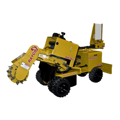
The Rayco RG74DXH is a high-production stump cutter
powered by a massive 3.8L Cummins 74hp diesel engine that
generates peak torque of 295ft-lbs. The large displacement
diesel engine delivers more cutting power than most 100hp-
class stump cutters and meets Tier 4 Final emissions
without complex after-treatment systems. Compared to the
competition, the difference is clear.
• Cummins QSF3.8 diesel engine meets Tier 4 Final/
Stage IV emissions
• Does not require Diesel Exhaust Fluid (DEF)
• Does not utilize Diesel Particulate Filter (DPF)
• Large displacement engine produces 74hp / 295ft-
lbs torque

RG74DXH Parts Manual
800.392.2686 5
Machine Specs
General
Weight: 5920 Lbs Maximum
Length: 190” Maximum
Height: 97” Maximum
Width: 83” Maximum
Chip Collection Capacity: 86cu. ft. (2435 liters) Minimum
Chassis Design: Electrically welded 4”x6”x3/8” (102x152x9.5
mm) wall rectangular steel tubing
Axle Capacity: 7000 lbs (3175 kg)
Telescoping Tongue (coupling) Extension: 60” 152.5 cm)
Minimum
Hitch: Adjustable height 2-5/16” (58.7 mm) Ball
Jack Stand: Hydraulic
Tires: (2) 235-75R-17.5H 6000LB
Engine
Model: Cummins 3.8L, Tier 4/Stage IV, Vertical 4-cycle, Turbo-
charged, Intercooler, Liquid Cooled, diesel
Number of cylinders: 4
Displacement: 229 cu. in
Maximum no load RPM: 2500
Gross HP at maximum no load RPM: 74 HP
Maximum rated torque: 295ft lbs @1300 RPM
Cooling medium: liquid cooled
Air Cleaner: Dry type with Pre-Cleaner
Oil Filter: Spin-on type
Fuel Tank Capacity: 24 gallons
Electrical System: 12 volts/135 AMP Alternator
Safety: Elastometric engine mounts required
Engine: to be operable on (up to) a 30° slope with the cutter
wheel in the full up or down position
Engine: must remain level with machine frame and not tilt
upward or downward while in operation. Also, engine must not
move left or right while in operation.
Hydraulic System - Cutter
Cutter Pump: Variable displacement axial piston
Cutter Motor: Fixed displacement axial piston
Cutter Pump Displacement: Electronic controlled with neutral
start
Command Cut: Swing speed control and horsepower optimizer
Filter: Easy access suction filter and pressure filter
Aux System Pressure Relief: 2250 psi (155 bar)
Lift & swing cylinders: 2 ½” bore x 7-3/8” stroke, 1-1/8” rod
Oil Type: Tellus T46
Hydraulic Tank Capacity: 24 Gallons
Cutting Wheel
Wheel Diameter: 28” Maximum
Wheel Thickness: 1” Minimum
Cutting Wheel Bearings: 2-3/16” diameter double row spherical
roller
Cutter Wheel RPM: 1000 RPM @ 2200 RPM Engine Speed
Drive Belt: MBL GigaTorque®
Cutting Teeth: RAYCO Super tooth™ forged, one piece, with
tungsten carbide tips.
Cutter Teeth Quantity: 40 Maximum
Belt Guard: Steel, one piece
Chip Retaining Curtains: Fabric impregnated rubber
Cutter Wheel: Must come to a stop in less than three seconds
without shutting off engine
Cutter Wheel Engagement: Hydrostatic pump. No clutch
necessary
Cutting Range (without repositioning)
Below Ground Level: 26”
Above Ground Level: 31”
Forward – Backward: 60” (152.4 cm) Minimum

RG74DXH Parts Manual
6
Serial Number Location & Information
VIN Numbers Location
Whenever communicating with Rayco or your Rayco dealer,
have your machine serial number handy, as it can help
pinpoint most exactly what information is needed in caring
for your machine.
It is attached to the machine at the location shown. For
ready reference, record it in the boxes provided on the
inside front cover of this manual.
For reference on communication regarding the engine,
record its model and serial numbers also in the boxes
provided on the inside front cover of this manual. See the
Engine Operator Manual for assistance in locating the
numbers on the engine.

RG74DXH Parts Manual
800.392.2686 7
Serial Number Location & Information
Identification Numbers
Model Number Serial Number
Machine
Engine
Implement
Implement
Dealer Information
Name
Address
Dealer Contact Phone Number Hours
Sales
Parts
Service
Serial number is located as shown.
Use the below table to record identification numbers and dealer information.

RG74DXH Parts Manual
8
Frame Assembly 37486 Rev A.
11 12
16 17 18
3
2
6
15
5
7
4
8
9
10
14
13
11920
ITEM QTY. PART # DESCRIPTION
1 1 760129 VALVE-ONE BANK JACKSTAND
2 1 3506 TONGUE CYL ASSY-TELESCOP
3 1 4100 TELE TONGUE WELD
4 1 38026 DECK PLATE ASSY
5 1 20540 WELD MAIN FRAME 140DXH
6 1 3515-01 FENDER ASSY-RH
7 1 3515-02 FENDER ASSY-LH
8 1 3504 HITCH ASSY 2 5/16
9 1 730036-132 CHAIN 3/8 HI TEST x 132”
10 15172 TRAVEL BLOCK ASSY
11 1 3501 PIN, TONGUE LOCK
12 1 728007 PIN-HAIR 3/4” X 1-1/16”
13 2 730037 GROMMET-RUBBER 7/8” ID
14 1 3713 TONGUE LIFT CYL ASSY
15 1 374 85 AXLE ASSY RG74DXH
16 1 805100 VALVE-CHECK DUAL PILOT PISTON
17 2 722306 BOLT HEX 3/8-16X1-3/4GR8
18 2 760261 NUT-HNNL 3/8-16 INS
19 2 722201 BOLT HEX 5/16-18 X 2 GR8
20 2 726202 WASHER LOCK 5/16” PLATED

RG74DXH Parts Manual
800.392.2686 9
Travel Block Assembly 5172
ITEM QTY. PART # DESCRIPTION
1 2 5237 TRAVEL BLOCK UHMW
2 1 5410-20 SHIM TRAVEL BLOCK
3 8 750383 BOLT-SHCS 3/8-16 X 1” SS
13
2

RG74DXH Parts Manual
10
Hitch Assembly 3504
5
4
6
2
3
1
ITEM QTY. PART # DESCRIPTION
1 1 3505 HITCH WELDMENT 2 5/16
2 1 728028 PIN-SAFETY SNAP 1/4 X 2 1/2
3 4 722506 BOLT HEX 1/2 - 13 X 2 GR8
4 8 726501 WASHER FLAT 1/2
5 4 724501 NUT HEX 1/2-13 GR8
6 4 726502 WASHER LOCK 1/2

RG74DXH Parts Manual
800.392.2686 11
Tongue Cylinder Assembly Telescope 3506
ITEM QTY. PART # DESCRIPTION
1 1 2719 CYLINDER WELD-TONGUE
2 2 2235 PIN, CYL. , TONGUE
3 1 3501 PIN, TONGUE LOCK
4 4 728004 PIN-COTTER 3/16 X 1-1/2
5 1 728007 PIN-HAIR 3/4” X 1-1/16”
6 2 761288 HOOK-SLIP W/LATCH 3/8”
2
1
6
4
3
5

RG74DXH Parts Manual
12
RH Fender Assembly 3515-01 Rev A.
35 6
1
587
2
4
ITEM QTY. PART # DESCRIPTION
1 1 3516-01 WELDMENT FENDER RH 120
2 1 1884-01 LIGHT BOX BRKT RH 72D
3 4 722110 BOLT WHIZ 1/4-20 X 3/4
4 4 722539 BOLT CARR 1/2”-13 X 1-1/2
5 4 724501 NUT HEX 1/2-13 GR8
6 4 726502 WASHER LOCK 1/2
7 1 73 0100 GROMMET-RUBBER 9/16” ID
8 1 73 0103 ELBOW-FLEX 3/8 90 DEGREE

RG74DXH Parts Manual
800.392.2686 13
LH Fender Assembly 3515-02 Rev A.
ITEM QTY. PART # DESCRIPTION
1 1 3516-02 WELDMENT FENDER LH 120
2 1 1884-02 LIGHT BOX BRKT LH 72D
3 4 722110 BOLT WHIZ 1/4-20 X 3/4
4 4 722539 BOLT CARR 1/2”-13 X 1-1/2
5 4 724501 NUT HEX 1/2-13 GR8
6 4 726502 WASHER LOCK 1/2
7 1 730100 GROMMET-RUBBER 9/16” ID
8 1 730103 ELBOW-FLEX 3/8 90 DEGREE
365
2
1
8
7
4

RG74DXH Parts Manual
14
Tongue Lift Cylinder Assembly 3713
1
2
4
6
5
6
3
3
ITEM QTY. PART # DESCRIPTION
1 1 RETRACTED CYLINDER-2 X 12
2 4 2721 LUG - CYLINDER 3-7/8
3 1 3501 PIN, TONGUE LOCK
4 1 728007 PIN-HAIR 3/4” X 1-1/16”
5 4 728012-HAIRPIN HAIR PIN
6 2 728012-PIN CYLINDER PIN

RG74DXH Parts Manual
800.392.2686 15
Axle Assembly 37485 Rev A
ITEM QTY. PART # DESCRIPTION
1 1 802570 AXLE-TORFLEX #12
2 2 765277 WHEEL/TIRE ASSY BAL
3 2 2033 GUARD, SEAL
4 2 800918 RING-CLAMPING LUG
WHEEL/AXLE
3.695
A
A
2
1
90°
1.388
7.398
SECTION A-A
3
3
4

RG74DXH Parts Manual
16
Deck Plate Assembly 6898 Rev A.
1
5
4
11
7
9
12
13
10
3
6
4
2
8
5
ITEM QTY. PART # DESCRIPTION
1 1 5045W DECK PLATE LH WELD
2 1 5046W DECK PLATE RH WELD
3 1 2689 BRACKET,CURTAIN LH
4 1 3189 CURTAIN-LH SIDE
5 14 750399 BOLT WHIZ 3/8-16 X 1” GR8.2 ZP
6 1 3190 CURTAIN-RH SIDE
7 1 2690 BRACKET,CURTAIN LH
8 8 722114 BOLT WHIZ 3/8-16 X 3/4 GR8.2 ZP
9 2 12422 DECK PLATE COVER
10 4750765 BOLT WHIZ 1/4-20 X 1/2
11 4 761219 PLUG-HOLE 3/8 PLASTIC
12 2 750089 PLUG-PANEL, 2IN. BLACK
13 4 722725 BOLT BHCS 3/8-16 X 3/4 ZP

RG74DXH Parts Manual
800.392.2686 17
Tail Section Front Assembly 37504 Rev B.
ITEM QTY. PART # DESCRIPTION
1 4 722307 BOLT-HEX 3/8-16 X 2
2 4 803487 WASHER-FENDER 3/8” X 1.5”
3 9 760261 NUT-HNNL 3/8-16 INS
4 6 750768 NUT-WHIZ 1/4-20 SERR FLANGE L/N
GR8 ZN
5 1 761641 TRIM-EDGE TRIM-LOK 1/4”
6 7 750399 BOLT WHIZ 3/8-16 X 1” GR8.2 ZP
7 7 750061 NUT-WHIZ 3/8-16 SERR FLANGE L/N
GR8 ZN
8 2 722110 BOLT WHIZ 1/4-20 X 3/4
9 6 722999 BOLT CAR 1/4-20 X 3/4
10 2 801361 KNOB 1/4-20
11 1 5174 KING PIN ASSY
12 1 37487 TAIL SECTION FRONT RG74DXH
13 1 3715-01 CYLINDER SWING-RH ASSY
14 1 3715-02 CYLINDER SWING-LH ASSY
15 1 5182 LIFT CYLINDER ASSY
16 1 1200015 VALVE-OVERCENTER
17 2722724 BOLT HEX 1/4-20 X 2 1/4
18 4 726101 WASHER FLAT 1/4 USS
19 2 726102 WASHER-LOCK, 1/4”
20 2 724101 NUT HEX 1/4-20 GR8
21 1 730025 CLAMP-VINYL COVERED 1”
22 1 37495 BATTERY BOX WELD RG74DXH
23 1 37498 BATTERY COVER WELD
24 1 37501 ECU MOUNT
25 1 37502 ECU BACK PLATE
26 1 760086 RELAY-STARTER T185/T275
27 1803760 RELAY-STARTER T185/T275
28 1 801240 FUSEHOLDER-FMG
29 1 805222 FILTER-HEAD DIFFERENTIAL 50PSI
30 1 805075 FILTER-HYD OIL RAYCO LOGO
31 1 805223 INDICATOR-DIFFERENTIAL
CLOGGING 36PSI
32 1 36304 ASSEMBLY, BATTERY RG74T-R
33 4 805385 CUMMINS ECU ISOLATOR
34 4 722306 BOLT HEX 3/8-16X1-3/4GR8
35 1 804956 FUSE
36 8.625”
X 13” 726959 RUBBER-MASTICATED 3/16”
37 136657 HARNESS, JUMPER OIL PRESSURE
38 1803667 RELAY-MINI 12V SPDT 40A SEALED
39 1 722308 BOLT-HEX 3/8-16 X 2-1/4
40 1 730038 STRAP-TARP W/S-HOOK 10”
41 2 726300 WASHER FLAT 3/8 SAE
51
79
80
81
9 4
9 4
9 4
585
72
58
44
78
67
6667686970
95
96
CUT RUBBER PAD TO
8.625" X 13"
107
97
75
10
7794
32
943
8382884
71
67
93
51
1
11
64
10887

RG74DXH Parts Manual
18
LH Swing Cylinder Assembly 3715-02 Rev A.
1
3
2
5
4
ITEM QTY. PART # DESCRIPTION
1 1 3514-02 WELDMENT CYL-SWING LH
2 2 2215 PIN, CYLINDER SWING
3 2 722201 BOLT HEX 5/16-18 X 2 GR8
4 2 730085 ZERK-GREASE 1/4-28 90DEG
5 2 750050 NUT LOCK 5/16-18 NYLON

RG74DXH Parts Manual
800.392.2686 19
RH Swing Cylinder Assembly 3715-01 Rev A.
ITEM QTY. PART # DESCRIPTION
1 1 3514-01 WELDMENT CYL-SWING RH
2 2 2215 PIN, CYLINDER SWING
3 2 722201 BOLT HEX 5/16-18 X 2 GR8
4 2 750050 NUT LOCK 5/16-18 NYLON
5 2 730085 ZERK-GREASE 1/4-28 90DEG
3
4
1
2
5

RG74DXH Parts Manual
20
Battery Assembly 36304 Rev A.
534
6
9
9
KEY SWITCH 12 AWG WIRE
CONNECTS TO 20 AMP FUSE
887
NOTE BATTERY ORIENTATION:
DO NOT CLAMP ACROSS VENT CAP!
1
2
8
20 AMP
FUSE
ITEM QTY. PART # DESCRIPTION
1 1 801476 BATTERY-C31S-XHD
2 1 36083 BATTERY TIE DOWN
3 2 726300 WASHER FLAT 3/8 SAE
4 2 760261 NUT-HNNL 3/8-16 INS
5 2 36084 J-HOOK, BATT TIE DOWN
6 1 804933 FUSE-BLOCK ATC/ATO 4 WAY
7 1 750109 FUSE-ATC, 20 AMP
8 3 750110 FUSE-ATC, 30 AMP
9 2 804607 NUT-3/8-16 STUD NUT SS
Other manuals for RG74DXH
1
Table of contents
Other Rayco Cutter manuals