Nakanishi PLANET600 Series User manual

0pt
取扱説明書 / OPERATION MANUAL
日本語 : P1 - P15 / English : P17 - P32 OM-K0679
PLANET600
高速ジグ研削用エアータービンスピンドル / High-Speed JIG Grinding Air Turbine Spindle
OM-K0679_PLANET600_(A5x)_JA_170710発注先変更準備(住所変更).indd 1 2017/07/18 13:54:58

OM-K0679_PLANET600_(A5x)_JA_170710発注先変更準備(住所変更).indd 2 2017/07/18 13:54:59

ENGLISH
17
Thank you for purchasing the High-Speed JIG Grinding Air Turbine Spindle " PLANET 600 ". This
Air Turbine Spindle is designed for I.D. grinding and can be installed on milling machines, jig boring
machines or special purpose machines. The Air Line Kit (with Lubricator) and a compressor are
required to drive this Air Turbine Spindle. Read this and all the associated component Operation
Manuals carefully before use. Always keep this Operation Manual in a place where a user can referred
to for reference at any time.
CONTENTS
1. CAUTIONS FOR HANDLING AND OPERATION ········································· P17
2. BASIC PACKAGE ················································································· P20
3. WARRANTY ························································································· P21
4. CONTACT US ······················································································· P21
5. FEATURES··························································································· P21
6. SPECIFICATIONS AND DIMENSIONS ······················································ P22
7. REPLACING THE GRINDSTONE ····························································· P23
8. REPLACING THE COLLET ····································································· P24
9. CONNECTION TO THE AIR LINE KIT ······················································· P25
10. BREAK-IN PROCEDURE········································································ P26
11. CAUTIONS WHEN USING GRINDSTONES················································ P27
12. DRESSING GRINDSTONES ( WA AND GC TYPE )······································ P28
13. USING THE ANTI-ROTATION BAR··························································· P28
14. JIG GRINDING METHOD IN A VERTICAL MILLING MACHINE······················ P29
15. CONFIRMING THE PART BORE DIAMETERS, COLLET DIAMETER AND
GRINDSTONE DIAMETER ······································································ P31
16. TROUBLESHOOTING ············································································ P31
17. DISPOSAL OF THE AIR TURBINE SPINDLE ············································· P33
CAUTIONS FOR HANDLING AND OPERATION
Class Degree of Risk
DANGER Existence of a hazard that could result in personal death or
serious injury, if the safety precautions are not followed.
WARNING
A safety hazard could result in bodily injury or damage
to the device if the safety instructions are not properly
followed.
CAUTION
A hazard that could result in light or moderate bodily injury
or damage to the device if the safety instructions are not
followed.
1.
■Read these warnings and cautions carefully and only use in the manner intended.
■These warnings and cautions are intended to avoid potential hazards that could result in personal
injury to the operator or damage to the device. These are classified as follows in accordance with
the seriousness of the risk.
OM-K0679_PLANET600_(A5x)_EN_170710発注先変更準備(住所変更).indd 17 2017/07/18 13:55:30

18
①Always install the Anti-Rotation Bar to the Air Turbine Spindle when installing this
spindle into the main spindle of the milling machine or jig boring machine. If the Anti-
Rotation Bar is not mounted to the Air Turbine Spindle, the supply air / oil hose will
become twisted and tangled, causing serious bodily harm and damage.
②Installation and operation the Air Turbine Spindle should be performed by a person
with experience with milling machines, jig boring machines, or special purpose
machines as well as the installation and plumbing of compressed air.
DANGER
①The Air Turbine Spindle is not a hand tool. It is designed to be used on milling
machines, jig boring machines or special purpose machines.
②Do not touch the grindstone while it is rotating. It is very dangerous.
③Wear safety glasses, dust mask, and use a protective cover around the Air Turbine
Spindle whenever the Air Turbine Spindle is rotating.
④Never handle or operate the Air Turbine Spindle until you have thoroughly read the
Operation Manuals and safe operating conditions have been confirmed.
1) To prevent injuries / damages, check the Air Turbine Spindle and grindstone for
proper installation, before operating the Air Turbine Spindle.
2) Before disconnecting the Air Turbine Spindle, always turn the control power off and
turn off the compressed air supply to the Air Line Kit. It is then safe to remove the
Air Turbine Spindle from the machine.
⑤When installing a grindstone, tighten the collet correctly, then re-check the collet
and collet nut before starting rotation. Do not over-tighten the collet. This may cause
damage to the spindle.
⑥Do not use bent, broken, chipped, out of round or sub-standard grindstones or shanks,
as this may cause them to vibrate, shatter or explode. Grindstones with fractures or a
bent shank will cause injury to the operator. When using a new grindstone, rotate it at
a low speed and increase speed gradually for safe operation.
⑦Do not exceed the recommended maximum allowable speed of the grindstone. For
your safety, use speeds below the grindstone manufacturers maximum allowable
speed.
⑧Do not apply excessive force. This may cause injury to the operator by slippage of the
shank or damage to the grindstone, causing a loss of concentricity and precision to
the Air Turbine Spindle.
WARNING
①Do not drop or hit this Air Turbine Spindle, as shock can damage to the internal
components.
②Before use, carefully read " Air Line Kit Operation Manual " regarding the correct
connection, operation and cautions when using the Air Line Kit.
③Be sure to clean the collet, collet nut and the inside of the spindle before installing a
grindstone. If ground particles or metal chips stick to the inside of spindle or the collet,
damage to the collet or spindle can occur due to the loss of precision.
CAUTION
OM-K0679_PLANET600_(A5x)_EN_170710発注先変更準備(住所変更).indd 18 2017/07/18 13:55:30

ENGLISH
19
④When cleaning the Air Turbine Spindle, stop the Air Turbine Spindle and remove
debris with a soft brush or a cloth. Do not blow air into the end of spindle area (refer
to section " 6 - 2 Outside View " ) with compressed air as foreign particles or grinding
debris may get into the ball bearing.
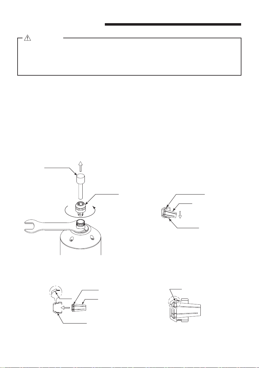
⑤Always clean the shank of the grindstone before installing the grindstone into the
spindle.
⑥When choosing the correct collet size to fit the shank of the grindstone, the collet size
tolerance of
-
0 〜+0.1mm maximum is strongly recommended. If the shank diameter
is any amount larger than the collet diameter, or, more than .1mm smaller than the
collet diameter, clamping will be improper and accuracy will be compromised.
⑦Operating the Air Turbine Spindle with insufficient Oil Lubrication will cause low
rotational speed, damage to the internal components and shorter life of the Air Turbine
Spindle.
⑧Be sure to drain moisture and condensation from the Air Line Kit (air filter bowl)
regularly to avoid moisture being carried to the Air Turbine Spindle. This may cause
damage to the Planet Air Turbine Spindle.
⑨Check to make sure the Air Turbine Spindle Shank is properly and securely mounted
in the machine prior to use. If the Air Turbine Spindle is not properly aligned or there is
excessive play, do not use the Air Turbine Spindle until this situation is corrected.
⑩Select suitable products or grindstones for all applications. Do not exceed the
capabilities of the Air Turbine Spindle or the grindstone.
⑪Do not stop the Air Turbine Spindle while coolant spray is being applied to the
grindstone. Removing the air pressure from the Air Turbine Spindle causes a loss of
purging, allowing the Air Turbine Spindle to ingest coolant and debris. This will cause
damage to the Air Turbine Spindle.
⑫Carefully direct coolant spray directly on the grindstone. Do not spray directly on the
Air Turbine Spindle body or the collet nut. Large amounts of coolant sprayed directly
on the Spindle end of the Air Turbine Spindle may cause excess load of the Spindle,
causing a loss of durability and longevity of the Air Turbine Spindle.
⑬Stop the Air Turbine Spindle immediately when extreme rotation fluctuations or
unusual vibration is observed. Immediately, check the content of section
" 16. TROUBLESHOOTING ".
⑭
Always check if the grindstone, collet, collet nut, connection hose and supply / oil hose
for damaged before and after operating.
⑮If the collet or collet nut show signs of wear or damage, replace them before a
malfunction or additional damage occurs.
⑯After installation, repair, initial operation, or long periods of non operation, please refer
to section " 10. BREAK-IN PROCEDURE ". When checking the Air Turbine Spindle, no
vibration or unusual sound should be observed during rotation.
⑰Do not disassemble, modify or attempt to repair the Air Turbine Spindle. Additional
damage will occur to the internal components. Service must be performed by NSK
NAKANISHI or an authorized service center.
⑱
When using this Air Turbine Spindle for mass production, please consider the purchase
of an additional Air Turbine Spindle to be used as a back-up in case of emergency.
CAUTION
OM-K0679_PLANET600_(A5x)_EN_170710発注先変更準備(住所変更).indd 19 2017/07/18 13:55:31

20
Table. 1 Packing List Contents
Air Turbine Spindle・・1pc.*1Collet Nut (K - 265)・・1pc.*2
Wrench (12 x 14)・・2pcs.
12
14
Supply Air / Oil Hose (K - 254:2m)
(with Filter Joint (FJ - 01))・・1pc.
Silencer・・1pc. Anti-Rotation Bar・・1set
Anti-Rotation Bar 1
Anti-Rotation Bar 2
Inspection Card・・1pc.
検査成績表
Inspection Card
Operation Manual・・1set
取扱説明書
OPERATION MANUAL
*1 Collet is sold separately. Please select the suitable collet size for your application.
*2 The collet nut is attached to the Air Turbine Spindle.
BASIC PACKAGE
2.
When opening the package, check if it includes all items listed in " Table. 1 Packing List Contents ".
In the event of any shortage, please contact either NAKANISHI (see the " 4. CONTACT US " section)
or your local dealer.
⑲Securely connect the compressor supply connection hose to the Air Line Kit, and,
connect the supply / oil hose to the Air Line Kit and the Air Turbine Spindle to avoid
accidental disconnection during use.
CAUTION
OM-K0679_PLANET600_(A5x)_EN_170710発注先変更準備(住所変更).indd 20 2017/07/18 13:55:32

ENGLISH
21
If the silencer is clogged or extremely dirty, the silencer is replaceable by the end-user (Refer to Table. 2).
Table. 2
Name Model Manufacturer
Silencer ANB1 - C08 SMC
Company Name
Business Hours
U.S. Toll Free No.
Telephone No.
Fax No.
Web Address
:
Industrial Div.
: 8:30am to 17:00pm (CST)
(closed Saturday, Sunday and Public Holidays)
: 800-585-4675
: 847-843-7664
: 847-843-7622
: www.nskamericacorp.com
Contact UsContact Us
For U.S. Market
Company Name
Business Hours
Telephone No.
e-mail Address
:
: 8:00am to 17:00pm
(closed Saturday, Sunday and Public Holidays)
: +81 (0) 289-64-3520
For Other Markets
WARRANTY3.
We provide a limited warranty for our products. We will repair or replace the products if the cause
of failure is due to the following manufactures defects. Please contact us or your local distributor for
details.
(1) Defect in manufacturing.
(2) Any shortage of components in the package.
(3) Where damaged components are found when initially opening the package.
(This shall not apply if the damage was caused by the negligence of a customer.)
CONTACT US4.
For your safety and convenience when purchasing our products, we welcome your questions.
If you have any questions about operation, maintenance and repair of the product, please contact us.
FEATURES5.
①
Air consumption is 175Nℓ/ min (6.18 CFM) and can be used with air compressor of 3HP (2.2 kW).
②This Air Turbine Spindle is designed to be used with adjustable boring heads.
③This Air Turbine Spindle is designed for inside surface grinding (I.D. Grinding) and can be installed
on milling machines, jig boring machines or special purpose machines.
④Various sizes of collets are available 0.5mm - 6.35mm (Refer to the " 6 - 1 Specifications
<Option>" ).
OM-K0679_PLANET600_(A5x)_EN_170710発注先変更準備(住所変更).indd 21 2017/07/18 13:55:32

22
6 - 2 Outside View
(18.87)
(16.1)
90
(148.9)
40
φ15.9
φ64
φ32
φD
End of Spindle Area
Model PL600 - M2040 PL600 - H3440
φDφ20 φ19.05
SPECIFICATIONS AND DIMENSIONS6.
6 - 1 Specifications
Model PL600 - M2040 PL600 - H3440
Rotation Speed 65,000min-1 (rpm) ±10% (55,000 - 72,000min-1 (rpm))
Appropriate Air Pressure 0.4MPa (58psi) (0.3 - 0.5MPa (43.5 - 72.5psi))
Air Consumption 175Nℓ/ min (130 - 210Nℓ/ min)
Shank Type φ20 Straight φ19.05 Straight
Weight 1,740g 1,735g
Noise Level at 1m distance Less than 80dB (A)
Temperature Humidity
Atmospheric Pressure
Operation Environment 0 - 40°CMAX.75%
(No condensation) 800 - 1,060hPa
Transportation and
Storage Environment -10 - 50°C 10 - 85% 500 - 1,060hPa
<Option>
Collet (CHK- □□ )φ0.5 - φ6.0mm in 0.1mm increments and φ2.35mm, φ3.175mm,
φ4.76mm, φ6.35mm
Collet Nut K - 265
Fig. 1
OM-K0679_PLANET600_(A5x)_EN_170710発注先変更準備(住所変更).indd 22 2017/07/18 13:55:33

ENGLISH
23
Loosen
Grindstone
Spindle Shaft
Tighten
Collet Nut
14
14
12
12
REPLACING THE GRINDSTONE7.
Do not tighten the collet without inserting the test bur or the tool shank into the collet, as
this will damage the collet, spindle or collet nut, causing difficulty removing the collet.
CAUTION
Please set the grindstone to minimize the overhang amount. 13mm is the maximum amount
of overhang to maintain high accuracy and safety.
RECOMMENDATION
①Set the provided 12mm wrench on the spindle shaft.
②Place the provided 14mm wrench on the collet nut and turn it counterclockwise to loosen the collet
and remove the grindstone (The first turn will loosen the collet nut, but the grindstone will not
release and turning will become stiff. Keep turning through the stiffness and the collet will open).
③Clean the collet, collet nut and spindle taper, then insert the new grindstone and tighten the collet
by turning clockwise. Do not over-tighten.
Fig. 2
OM-K0679_PLANET600_(A5x)_EN_170710発注先変更準備(住所変更).indd 23 2017/07/18 13:55:33

24
12
14
Loosen
Grindstone
Collet Nut
Latch
Latch
Groove
Collet
Collet Nut
Collet Nut
DOWN
Collet
Wrench Seat
Fig. 3 Fig. 4
Fig. 5 Fig. 6
REPLACING THE COLLET8.
When installing the collet into the collet nut, be sure to fully engage the latch inside the
collet nut to the groove on the collets outer diameter area. It is very important to note that
if the collet is attached without being engaged with the latch of the collet nut, the collet will
stick inside the spindle taper, and this may cause damage to the collet and or the spindle.
CAUTION
①Remove the grindstone according to the section " 7. REPLACING THE GRINDSTONE "
procedure above and remove collet nut assembly (Fig. 3).
②The collet and collet nut are secured by a groove in the collet and a flange in the collet nut. To
remove the collet hold the collet nut in one hand and push diagonally down on the collet. The
collet should be released (Fig. 4).
③To install the collet, hold the collet at a slight angle, and insert it into the collet nut (Fig. 5).
Press the collet in the collet nut by positioning the collet in the collet nut and pressing down on flat
surface (Fig. 4).
Be sure to fully engage the latch inside the collet nut into the groove on the collet's outer
circumference area (Fig. 6).
OM-K0679_PLANET600_(A5x)_EN_170710発注先変更準備(住所変更).indd 24 2017/07/18 13:55:34

ENGLISH
25
Lubricating Oil
Use ISO VG15 Liquid Paraffin (Shell Ondina Oil #15) in the Air
Line Kit lubricator bowl (For U.S.A. specification, use Chevron
Superla #9).
Model
・Lubricating Oil (K - 211) 70cc
・Lubricating Oil (K - 202) 1ℓ
Make sure to turn the compressed air supply to the Air Line Kit OFF, before replacing the
Lubricating Oil or draining the water in Lubricating Oil.
CAUTION
①Connect the air hose to the φ6 One - Touch Joint on the Air Line Kit.
②Connect the silencer to the φ8 One - Touch Joint of the Air Turbine Spindle.
③Connect the Filter Joint of the supply air / oil hose to the Secondary Joint (
φ6 One - Touch Joint)
of the Air Line Kit (Fig. 7 ①).
④Fill Oil Reservoir through the Oil Filler Cap with recommended NAKANISHI Lubricating Oil
(K - 211 : Air Line Kit's Standard Accessories) to Upper Limit. Disconnect from air supply prior to
opening Oil Filler Cap. Do not over or under fill.
⑤Connect the connection hose (Air Line Kit's Standard Accessories) to the Primary Joint of the Air
Line Kit and Compressor (Fig. 7 ②).
⑥Supply air from the air compressor and turn the Regulator Knob to set air pressure between
0.3 - 0.5 MPa (43.5 - 72.5psi).
⑦Turn the ON / OFF Valve to ON and rotate the Air Turbine Spindle according to the recommended
proper air pressure.
Adjust the Oil Drip Rate of the AL - M1202 to the recommended volume which is 1drop / min.
(Commercially Air Line Kit has the same Oil Drip Rate).
* Refer to the Operation Manual of the Air Line Kit for detailed information.
⑧Be sure to adjusted to proper Oil Drip Rate before using the Air Turbine Spindle.
⑨Variations in rotational speed may occur due to the instability of the oil amount at the beginning of
use. When initially starting the Air Turbine Spindle, the rotational speed of the Air Turbine Spindle
may fluctuate. The rotation must be stable before using.
If the Oil Bowl of the Lubricator is overfilled, fluctuation in rotation will occur. Incorrect Oil Type will
also cause rotation fluctuations.
・When connecting the Compressor and Air Line Kit, it is recommended install an Air
Filter and Air Dryer to between Compressor and Air Line Kit in order to supply clean
dry air to the Air Turbine Spindle. Using compressed air containing excessive moisture
could result in malfunction or failure of the Air Turbine Spindle. If excessive moisture
or condensation are found in Air Filter Bowl, it will be necessary to install an Air Dryer
and larger air filter on the Primary Joint side of the Air Line Kit to prevent and remove
excessive moisture.
・Connect the input air supply connection hose and supply air / oil hose securely to avoid
accidental disconnection during use. Input air pressure should never exceed 1.0MPa
(145psi). Air pressure exceeding 1.0MPa (145psi) may cause the supply connection hose
and or air / oil hose supply to rupture.
CAUTIONS IN USING AIR LINE KIT
CONNECTION TO THE AIR LINE KIT9.
OM-K0679_PLANET600_(A5x)_EN_170710発注先変更準備(住所変更).indd 25 2017/07/18 13:55:34

26
Regulator Knob
Adjusting Dome ON / OFF Valve
To Air Compressor
Connection Hose
Connector for Air Hose
Primary Joint
φ6 One - Touch
Joint
Filter Joint
Silencer
Supply Air /
Oil Hose
Secondary Joint
①
②
Oil Filler Cap
・Make sure operation air pressure is less than 1.0MPa (145psi) before connecting the
input supply connection hose and air / oil supply hose. If operation air pressure is
exceeds 1.0MPa (145psi), injury to the operator may occur by accidental disconnection
before or during use.
・Before use, carefully read " Air Line Kit Operation Manuals " regarding the correct
connection, operation and cautions when using the Air Line Kit.
CAUTIONS IN USING AIR LINE KIT
Fig. 7 Connection of Air Line Kit " AL - M1202 (Sold Separately) "
BREAK-IN PROCEDURE10.
During transportation, storage or installation, the oil inside the bearings may settle. If the Air Turbine
Spindle is suddenly run at high-pressure, the bearings may not have sufficient lubrication, causing
excessive heat that will cause bearing damage.
After installation, repair, initial operation, or long periods of non operation, please carry out break-in as
follow. Slowly supply the air pressure to the Air Turbine Spindle over a period of 10 minutes, increasing
the supply air pressure until working pressure is reached.
OM-K0679_PLANET600_(A5x)_EN_170710発注先変更準備(住所変更).indd 26 2017/07/18 13:55:35

ENGLISH
27
13
Fig. 8
CAUTIONS WHEN USING GRINDSTONES11.
3.14 x Diameter (mm) x Rotation Speed (min-1) (rpm)
Surface Speed (m / s) = 1,000 x 60
The maximum surface speed or rpm is always specified for a grindstone. Do not exceed
the maximum speed with reference to the calculating chart below. Always follow the
grindstone manufacturer's recommendations.
CAUTION
①The proper surface speed for general grindstones is 10 - 30m / s.
②Do not exceed 13mm of overhang for mounted grindstones as shown in Fig. 8. If the overhang
must exceed 13mm, reduce the Air Turbine Spindle rotation speed in accordance with Table. 3.
③Dress the grindstone prior to use.
④Do not use grindstones with bent or broken shanks, cracks or excessive run-out.
⑤For grinding, the maximum depth of cut should not exceed 0.005mm radially or axially.
Reciprocate the grindstone several times after each pass to eliminate grindstones tool pressure.
⑥Keep the shank of the grindstone, collet and collet nut clean. If contaminants are left in the collet
or collet nut, excessive run-out will cause damage to the grindstone and or Air Turbine Spindle.
⑦Do not strike or disassemble the Air Turbine Spindle.
⑧Always set the grindstone to minimize the amount of overhang. 13mm is the maximum amount of
overhang to maintain high accuracy and safety.
Table. 3 Overhang and Speed
Overhang (mm) Max. Speed (min-1) (rpm)
20 N x 0.5
25 N x 0.3
50 N x 0.1
*N=Max. Operating Speed with 13mm overhang.
OM-K0679_PLANET600_(A5x)_EN_170710発注先変更準備(住所変更).indd 27 2017/07/18 13:55:35

28
Tighten
Anti-Rotation Bar 2
(female thread)
Anti-Rotation Bar 1
(male thread)
Fig. 10
Diamond Tool
8 - 18°
DRESSING GRINDSTONES ( WA AND GC TYPE)12.
The grindstone's center-core is runout before dressing. Be sure to dressing the grindstone
before grinding work.
CAUTION
<When using Grindstone with a center hole (shankless), always dress the stone>
①Mount the grindstone that will be used for Jig Grinding in the Air Turbine Spindle.
②Install the Air Turbine Spindle into the main spindle of the Milling Machine.
③Rotate the Air Turbine Spindle to a rotation speed of approximately 30,000 - 40,000min-1 (rpm).
Place dressing tool near the grindstone at an approximate angle of 8 - 18 degrees.
④Gradually move the diamond dresser tool until it lightly comes in contact with the grindstone.
⑤Dress the grindstone by moving the main spindle of the milling machine up and down.
⑥Gradually move the diamond dresser tool toward the grindstone until outer circumference of the
grindstone is completely uniform and free of vibration and run-out.
Fig. 9
USING THE ANTI-ROTATION BAR13.
Use the Anti-Rotation Bar (Included) and Block (Not Included) for your safety. Should the main spindle
be accidentally rotated, the Anti-Rotation System will prevent tangling of the supply air / oil hose.
①Thread the Anti-Rotation Bar 1 (male thread)
into the Anti-Rotation Bar 2 (female thread)
(Fig. 10).
②Thread the Anti-Rotation Bar into the Outward
Rotation Ring of the Air Turbine Spindle before
use. Refer to Fig. 11.
OM-K0679_PLANET600_(A5x)_EN_170710発注先変更準備(住所変更).indd 28 2017/07/18 13:55:35

ENGLISH
29
Block (Not Included)
(not included / provided
by the end-user)
Anti-Rotation Bar
(Standard Accessories)
Reducer
Boring Head
Outward Rotation
Ring
Fig. 11
JIG GRINDING METHOD IN A VERTICAL MILLING MACHINE14.
・Be sure to rotate the main spindle of the milling machine in less than 120min-1 (rpm).
Rotating the main spindle in more than 120min-1 (rpm) may cause the Air Supply Hose
to disconnect from the Air Turbine Spindle that can lead to tool breakage, a serious
accident and severe injury.
・Be sure to mount the Anti-Rotation Bar to the Air Turbine Spindle when installing it on
a vertical milling machine. If you do not attach the Anti-Rotation Bar to the Air Turbine
Spindle, it may cause the supply air / oil hose to become tangled, causing a serious
accident and or injury.
DANGER
When installing the Air Turbine Spindle to a vertical milling machine, ensure that the
vertical milling machine is grounded in order to avoid risk of an electric shock.
WARNING
When installing the Air Turbine Spindle in the machine spindle, do not hit, drop or cause
shock to it at any time. This may cause damage to internal components and result in
malfunctions and loss of accuracy.
CAUTION
OM-K0679_PLANET600_(A5x)_EN_170710発注先変更準備(住所変更).indd 29 2017/07/18 13:55:36

30
①Installing the work materials onto the holder.
②Align and indicate the center of the milling machines main spindle to the center of the hole on the
work material.
③Install the adjustable boring head into the main spindle of the vertical milling machine.
④Install the Air Turbine Spindle into the adjustable boring head.
⑤Thread the Anti-Rotation Bar into the Outward Rotation Ring of the Air Turbine Spindle before use.
Refer to section " 13. USING THE ANTI-ROTATION BAR ".
⑥Rotate the main spindle of the milling machine by hand. Place and mount the Block (provided
by the end-user) in a position where the Anti-Rotation Bar will come in contact with the block
completely.
⑦Rotating the Air Turbine Spindle, adjust the eccentricity amount of the adjustable boring head until
the grindstone lightly comes in contact with the work material to be ground.
⑧Rotate the main spindle on the milling machine a maximum of 120 min-1 (rpm) and begin to grind
the work piece.
⑨Reciprocate the grindstone several times after each pass to eliminate grindstone tool pressure.
⑩Stop the rotation of the main spindle on the milling machine.
Adjust the eccentricity amount of the adjustable boring head then repeat the procedure (Refer to
" 11. CAUTIONS WHEN USING GRINDSTONES " ).
Anti-Rotation Bar
(Standard Accessories)
Reducer
Outward Rotation Ring
Block (Not Included)
(not included / provided
by the end-user)
φB
φC
A
Boring Head
Fig. 12
2A (Eccentricity amount) + B (Outside diameter of the grindstone axis) = C (Bore of Work)
OM-K0679_PLANET600_(A5x)_EN_170710発注先変更準備(住所変更).indd 30 2017/07/18 13:55:36

ENGLISH
31
TROUBLESHOOTING16.
If a problem or concern occur, please check the following items prior to consulting your dealer.
Trouble Cause Inspection / Corrective Action
The Air Turbine Spindle
does not rotate or rotate
smoothly.
Air flow does not reach the
Air Turbine Spindle.
Check if input supply connection hose
or air / oil supply hose is broken, bent or
disconnected.
Check connection of the input supply
connection and air / oil supply hoses.
Check the compressor power supply and
the air compressor output.
Check the Regulator and set to the correct
air pressure.
Check all connections input supply and air /
oil supply hose.
The spindle ball bearings
have been damaged.
Replace the ball bearings.
(Return to NAKANISHI dealer service.)
Air Turbine Spindle
rotation speed is too
slow.
The connection hose or air /
oil supply hose have been
damaged.
Replace the input supply and or air / oil
supply hoses.
Poor connection of input
supply or air / oil supply
hose.
Check all threaded joints and re-tighten if
necessary.
Low air pressure. Check the Compressor, Air Circuit, and
Regulator.
Low Lubricating Oil. Check lubricator for proper lubricant level.
Set the Oil Drip Rate 1 drops / min. if using
the AL - M1202 Air Line Kit or commercially
available Air Line Kit.
Water, dirt and debris are
collected in the Air Filter.
Drain water, dirt and debris from the Air
Filter Bowl.
Work Hole Diameter Collet Diameter Recommended Grindstone Diameter
Less than φ13.0mm φ3.0mm Less than φ6.0mm
Less than φ70.0mm φ6.0mm Less than φ16.0mm
Be sure to confirm the grindstone manufactures maximum rotation speed for that
grindstone before rotating the spindle. If using the grindstone beyond the maximum
rotational speed of the grindstone, damage to the grindstone, spindle or malfunction to the
collet or spindle will occur.
CAUTION
When using a grindstone, select the correct collet diameter for the corresponding shank size and
grindstone diameter according to diameter of the bore to be ground (Refer to Table. 4).
Table. 4
CONFIRMING THE PART BORE DIAMETERS, COLLET DIAMETER AND
GRINDSTONE DIAMETER
15.
OM-K0679_PLANET600_(A5x)_EN_170710発注先変更準備(住所変更).indd 31 2017/07/18 13:55:37

32
Trouble Cause Inspection / Corrective Action
Air Turbine Spindle
rotation speed is too
slow.
Water in Lubricating Oil
reservoir.
Drain water from Lubricating Oil reservoir
and replace with clean Lubricating Oil.
Air Turbine Spindle
is Oscillating during
rotation.
Lubricator inclined or
upside down.
Inclined or upside down lubricator will flood
spindle with Lubricating Oil.
Excessive Oil Drip Rate
flooding the bearings.
Oil drip rate exceeds the recommended
amount.
Adjust for the proper Oil Drip Rate.
Over filled lubricator. Drain the Lubricating Oil from Reservoir to
meet indicated levels. Excess lubricant will
flood spindle.
Draining the Lubricating Oil until upper
limit below by opening the Drain Valve.
Overheating during
rotation.
Cutting debris has
contaminated the ball
bearings, and the ball
bearings are damaged.
Replace the ball bearings.
(Return to NAKANISHI dealer service.)
Abnormal vibration or
noise during rotation.
The shank of the grindstone
is bent or the grindstone
need to be dressed.
Replace or dress the grindstone.
Cutting debris has
contaminated the ball
bearing.
Replace the ball bearings.
(Return to NAKANISHI dealer service.)
The spindle ball bearings
have been damaged.
Grindstone slippage. Collet or collet nut is not
correctly installed.
Check and clean the collet and collet nut.
Reinstall the collet and collet nut.
The collet and the collet
nut are worn.
Incorrect collet size for the
grindstone shank.
Replace the collet and collet nut.
High run-out. The grindstone shank is
bent.
Change the grindstone.
Collet nut is not correctly
installed.
Secure the collet and the collet nut
correctly.
The collet and the collet
nut are worn.
Incorrect collet size for the
grindstone shank.
Replace the collet and the collet nut.
Inside of the spindle is
worn.
Replace the spindle shaft.
(Return to NAKANISHI dealer service.)
High run-out. Contaminants inside the
collet and the collet nut or
the spindle.
Clean the collet, collet nut and the inside
of the taper and spindle.
The spindle ball bearings
have been damaged.
Replace the ball bearings.
(Return to NAKANISHI dealer service.)
Refer to the Air Line Kit (AL - M1202) Operation Manual.
OM-K0679_PLANET600_(A5x)_EN_170710発注先変更準備(住所変更).indd 32 2017/07/18 13:55:37

ENGLISH
33
DISPOSAL OF THE AIR TURBINE SPINDLE17.
When disposal of this Air Turbine Spindle is necessary, follow the instructions from your local
government agency for proper disposal of industrial components.
OM-K0679_PLANET600_(A5x)_EN_170710発注先変更準備(住所変更).indd 33 2017/07/18 13:55:37

2017.07.18 001
OM-K0679_PLANET600_(A5x)_EN_170710発注先変更準備(住所変更).indd 34 2017/07/18 13:55:37
This manual suits for next models
2
Table of contents
Other Nakanishi DC Drive manuals