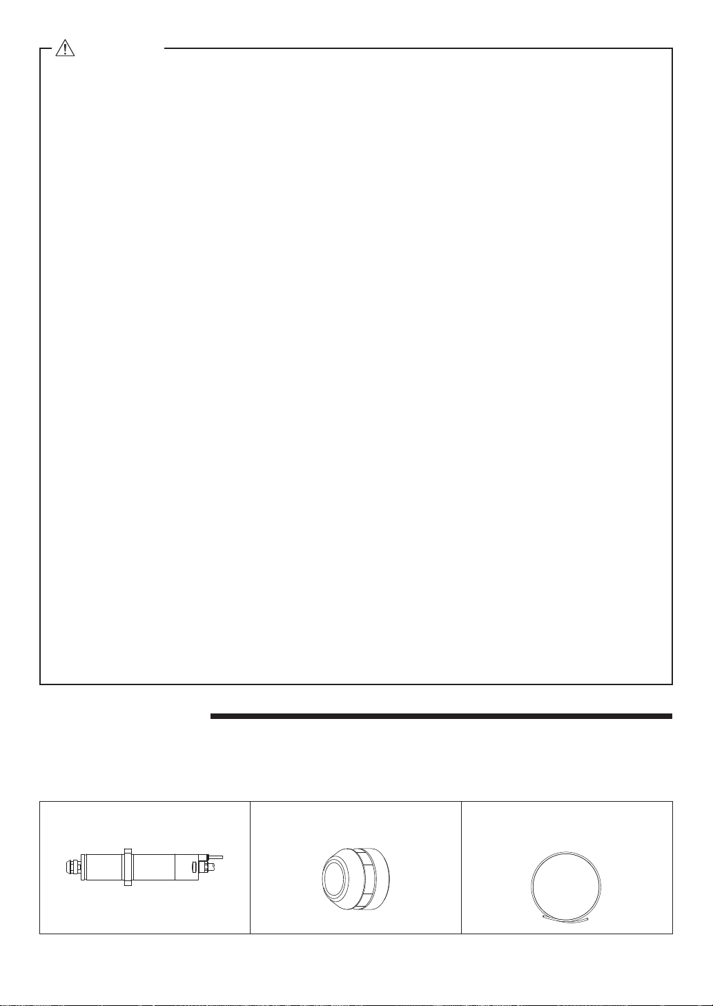
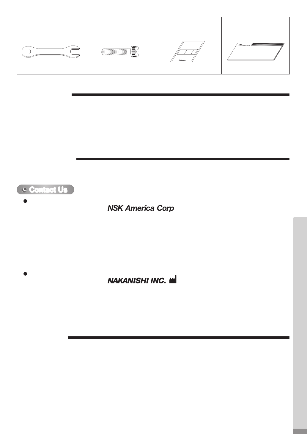
Nakanishi EMSF-3060K-RBT User manual

このたびは、モータスピンドル「EMSF-3060K-RBT」をお買い求め頂きまして、誠にありがとうございます。
本製品は、研削・小径エンドミル・小径ドリル加工等に使用できるモータスピンドルです。本製品をご使用頂くた
めには、E3000 コントローラおよびエアーラインキットが必要です。ご使用前に本取扱説明書および上記製品の
取扱説明書をよくお読み頂き、末永くご愛用くだされば幸いです。また、本取扱説明書は、ご使用になられる方が
いつでも見ることができる場所に保管してください。
1. 安全上の注意事項・表示について
■ 使用前に必ずこの安全上の注意をよくお読み頂き、正しくお使いください。
■ ここに示した注意事項は、製品を安全にお使い頂き、あなたや他の人への危害や損害を未然に防止するものです。
危害や損害の大きさと切迫の程度に分類しています。いずれも安全に関する内容ですから、必ずお守りください。
注意区分 危害や損害の大きさと切迫の程度
警 告 「人が傷害を負ったり、物的損害の発生がある注意事項」を説明しています。
注 意 「軽傷または中程度の傷害、または、物的損害が発生する可能性がある注意事項」を
説明しています。
警 告
① 本製品は、ハンドツールではありません。お手持ちの工作機械および専用機に取り付けてご使用ください。
② 危険ですので回転中は回転体に手を触れないでください。
③ 安全のため、回転中は保護覆い、保護メガネ、防塵マスクを使用してください。
④
濡れた手で電源コードプラグの抜き挿しおよびモータコードに触れないでください。感電のおそれがあります。
⑤ 安全を確認するまでは、本製品の取り扱い・取り外しを絶対にしないでください。
1)本製品を取り扱うときは、各種の損害を防止するため、設置機器の安全を確認してから取り扱ってく
ださい。
2)本製品を取り外すときは、設置機器の安全を確認し、エネルギー源である電源や供給エアーを遮断し、
該当する設備システム内の圧縮エアーを排気してから取り外してください。
⑥ 本製品を取り付ける際は、ホルダが機械のアースに接続されていることを確認してください。接続されて
いないと故障や漏電のときに感電のおそれがあります。
⑦
工具を取り付けるときは、コレットの締め付けを確実におこない(コレットの締めすぎには注意してくださ
い。締めすぎによりスピンドルが破損することがあります。)ご使用前にもう一度コレットとコレットナット
をご確認ください。
⑧ 粗悪な工具(バランスが悪い、芯振れが大きい、シャンクの曲がり等のあるもの)は使用しないでください。
使用するとシャンクが曲がったり、折れたりし、けがをするおそれがあります。初めて使用する工具を回
転させる場合は、始めに低速で回し、安全を確認しながら徐々に回転速度を上げてください。
⑨ 工具は、許容範囲内の回転速度で使用してください。許容範囲を超えた回転速度での使用は、工具破損に
よるけが、物的損害のおそれがあります。
⑩ 加工中に極端な負荷(切り込み量、送り量の過多)をかけないでください。極端な負荷により工具の破損
によるけが、物的損害のおそれがあります。
EMSF - 3060K - RBT
モータスピンドル / Motor Spindle
取扱説明書/ OPERATION MANUAL
日本語:P1 - P8 / English:P9 - P16 001
OM-KK0902JA
1
OM-KK0902JA001_モータスピンドル EMSF-3060K-RBT 取説 日英_下版_200420.indd 1 2020/04/20 10:56:30

Thank you for purchasing the Motor Spindle " EMSF-3060K-RBT ". This Motor Spindle is designed for grinding,
small diameter drilling and milling, etc. The E3000 CONTROLLER and Air Line Kit are rquired to drive this Motor
Spindle.
Read this and all the associated component Operation Manuals carefully before use. Always keep this Operation
Manual in a place where a user can referred to for reference at any time.
1. CAUTIONS FOR HANDLING AND OPERATION
■Read these warnings and cautions carefully and only use in the manner intended.
■These warnings and cautions are intended to avoid potential hazards that could result in personal injury to the
operator or damage to the device. These are classified as follows in accordance with the seriousness of the risk.
Class Degree of Risk
WARNING A safety hazard could result in bodily injury or damage to the device if
the safety instructions are not properly followed.
CAUTION A hazard that could result in light or moderate bodily injury or damage
to the device if the safety instructions are not followed.
①This Motor Spindle is not a hand tool. It is designed to be used on CNC machines or special purpose
machines.
②Do not touch the cutting tool while it is running. It is very dangerous.
③Wear safety glasses, dust mask, and use a protective cover around the Spindle whenever the Spindle
is rotating.
④Never connect, disconnect or touch the Power Cord Plug or Motor Cord Plug with wet hands. This
may cause an electric shock.
⑤Never operate or handle the Motor Spindle until you have thoroughly read the Operation Manuals
and safe operation has been confirmed.
1) To prevent injuries / damages, check the Motor Spindle and cutting tool for proper installation,
before operating the Motor Spindle.
2) Before disconnecting the Motor Spindle, always turn the control power off and turn the
compressed air supply to the CONTROLLER off. Then it is safe to remove the Motor Spindle.
⑥Whenever installing a Motor Spindle to a fixed metal base, ensure that the fixed metal base is
grounded in order to avoid risk of an electric shock.
⑦When installing a tool, tighten the collet correctly and check again the collet and collet nut before
use. Do not over-tighten the collet. This may cause damage to the spindle.
⑧Do not use bent, broken, chipped, out of round or sub-standard tools, as this may cause them to
shatter or explode. Tools with fractures or a bent shank will cause injury to the operator. When using
a new tool, rotate it in a low speed and increase speed gradually for safety.
⑨Do not exceed the recommended maximum allowable speed of the tool. For your safety, use speeds
below the maximum allowable speed.
⑩Do not apply excessive force. This may cause injury to the operator by slippage or damage of
the tool, or loss of concentricity and precision of the Motor Spindle.
WARNING
9
English
OM-KK0902JA001_モータスピンドル EMSF-3060K-RBT 取説 日英_下版_200420.indd 9 2020/04/20 10:56:34

Motor Spindle・・1pc.
EMSF - 3060K - RBT
Collet Nut (K - 265)・・1pc.* Air Hose・・1pc.*
EMSF - 3060K - RBT : 0.3m
CAUTION
①Do not drop or hit this Motor Spindle, as shock can damage to the internal components.
②Be sure to clean the collet and collet nut, the inside of the spindle before replacing the tool
(cutting tool). If ground particles or metal chips stick to the inside of spindle or the collet,
damage to the collet or spindle can occur due to the loss of precision.
③When cleaning a Motor Spindle, stop the Motor Spindle and remove debris with a soft brush or
a cloth. Do not blow air into the dust proof cover area (refer to section " 6 - 2 Outside View ")
with compressed air as foreign particles or cutting debris may get into the ball bearing.
④Always clean the tool shank before installing the tool in the Motor Spindle.
⑤
When sizing the correct collet size to the tool shank diameter, a tolerance of +0 〜
-
0.01mm is
strongly recommended. A tool shank within the +0 〜
-
0.1mm range is mountable, however,
this may cause poor concentricity and or insufficient tool shank gripping force.
⑥
Select suitable products or tools for all applications. Do not exceed the capabilities of the Motor
Spindle or tools.
⑦Do not stop the supply cooling air for motor during operation of the machine.
Removing the air pressure from the Motor Spindle causes a loss of purging, allowing the Motor
Spindle to ingest coolant. This will cause damage to the Motor Spindle.
⑧Carefully direct coolant spray directly on the tool. Do not spray directly on the Motor Spindle
and collet nut. Large amounts of coolant sprayed directly on the Motor Spindle may cause
excess load of the Motor Spindle causing a loss of durability and longevity of the Motor
Spindle.
⑨Stop working immediately when abnormal rotation or unusual vibration are observed.
Immediately, please check the content of section " 13. TROUBLESHOOTING ".
⑩Always check if the tool, collet, collet nut, connection hose and supply air hose for damaged
before and after operating.
⑪If the collet or collet nut show signs of wear or damage, replace them before a malfunction or
additional damage occurs.
⑫After installation, repair, initial operation, or long periods of non operation, please refer to
section " 11. BREAK-IN PROCEDURE " detailed in Table 2. When checking the Motor Spindle,
no vibration or unusual sound should be observed during rotation.
⑬
Do not disassemble, modify or attempt to repair this Motor Spindle. Additional damage will
occur to the internal components. Service must be performed by NSK NAKANISHI or an
authorized service center.
⑭When using this Motor Spindle for mass production, please consider the purchase of an
additional Motor Spindle to be used as a back-up in case of emergency.
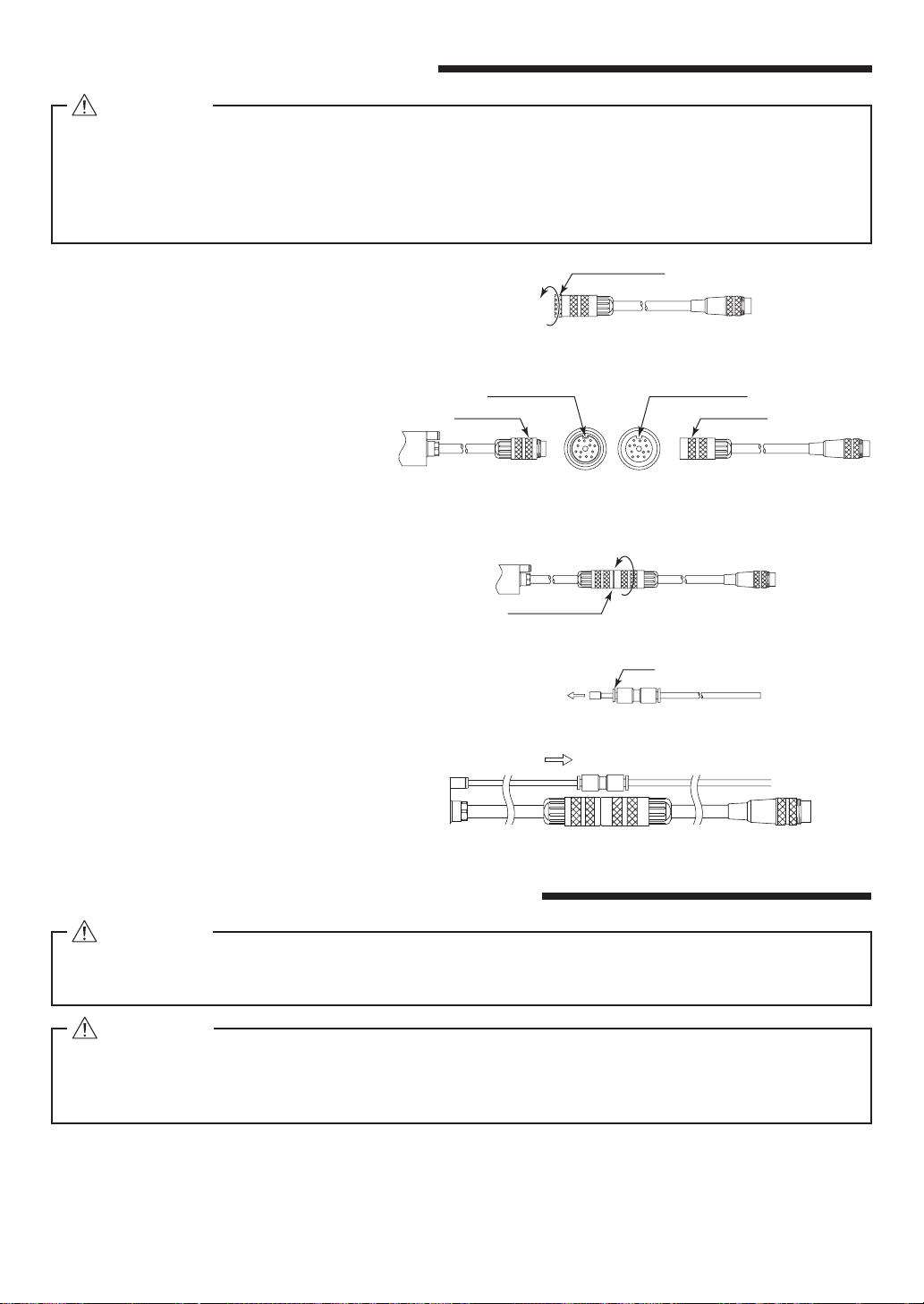
⑮Securely connect the compressor supply connection hose and the air hose to the Air Line Kit
and the Motor Spindle to avoid accidental disconnection during use.
Table 1. Packing List Contents
When opening the package, check if it includes all items listed in " Table.1 Packing List Contents ".
In the event of any shortage, please contact either NAKANISHI (see the " 4. CONTACT US " section) or your local dealer.
2. BASIC PACKAGE
10
OM-KK0902JA001_モータスピンドル EMSF-3060K-RBT 取説 日英_下版_200420.indd 10 2020/04/20 10:56:35

* The collet nut and Air Hose are attached to the Motor Spindle.
Wrench (12 ×14)
・・2pcs.
Hexagon Socket Head
Screw (M4 x 16)
・・4pcs.
Inspection Card
・・1pc.
Operation Manual
・・1set
検査成績表
Inspection Card
○○○○○○○○○○○
○○○○○○○○○
□□
○○○○
□□.
□□□□
□ □
□□□□□□□
□□□□□□
□□□□□□□
□□□□□□
□□□□□□□
□□□□
□□□□□□□
□□□□
□□□□□□
□ □ □
□□□
□□□
□□□□□□□□□□□□□□□□□□□□□□□□
□□□□□□□□□□□□□□□□□□□□□□□□
□□□□□
□□□□□□□□□□
□□□□□□□□□□□□□□□□□□□□□□□□
□□□□□□□□□□□□□□
□□□□□□□□□□
取扱説明書
OPERATION MANUAL
12
14
3. WARRANTY
We provide a limited warranty for our products. We will repair or replace the products if the cause of failure is due
to the following manufactures defects. Please contact us or your local distributor for details.
⑴Defect in manufacturing.
⑵Any shortage of components in the package.
⑶Where damaged components are found when initially opening the package.
(This shall not apply if the damage was caused by the negligence of a customer.)
4. CONTACT US
For your safety and convenience when purchasing our products, we welcome your questions.
If you have any questions about operation, maintenance and repair of the product, please contact us.
Company Name
Business Hours
U.S. Toll Free No.
Telephone No.
Fax No.
Web Address
:
Industrial Div.
: 8:30am to 17:00pm (CST)
(closed Saturday, Sunday and Public Holidays)
: 800-585-4675
: 847-843-7664
: 847-843-7622
: www.nskamericacorp.com
Contact UsContact Us
For U.S. Market
Company Name
Business Hours
Telephone No.
Web Address
:
: 8:00am to 17:00pm
(closed Saturday, Sunday and Public Holidays)
: +81 (0) 289-64-3520
For Other Markets
①The Motor Spindle housing is made from precision ground, hardened, stainless steel (SUS) with an outside
diameter of φ30mm.
②Excellent durability and high reliability are obtained by using a high-speed brushless motor, which eliminates
the need for brush replacement and frequent maintenance.
③A quick disconnect cord is available for easy brushless motor removal.
④Various sizes of collets are available CHK 0.5mm - 6.35mm. Standard collet is CHK 3.0mm or CHK 3.175mm.
(For U.S. market CHK 3.175mm.)
5. FEATURES
11
English
OM-KK0902JA001_モータスピンドル EMSF-3060K-RBT 取説 日英_下版_200420.indd 11 2020/04/20 10:56:35

33
43
35°
R23
φ39
(50.5)
8
50
(11)
(300)
(27.8)
108.5
12.5
(16.9)
136.3
(153.2)
Body mounting hole
4-φ4.2 Through hole
φ15.9
φ29.9
φ18.5
No clampingNo clamping
φ30
Dust proof cover area
- 0.01
0
6 - 2 Outside View
Fig. 1
6 - 3 Torque Characteristics
Torque (cN・m)
Output (W)
Continuous Duty AreaContinuous Duty Area
Torque
Output
450
400
350
300
250
200
150
100
50
0
9
8
7
6
5
4
3
2
1
0 10 20 30 40 50 60
Torque
Output
Speed (×103min-1) (rpm)
Model EMSF-3060K-RBT
Maximun Motor Rotation Speed 60,000min-1 (rpm)
Spindle Accuracy Less than 1µm
Max. Output 350W
Weight 600g
Noise Level at 1m distance Less than 65dB
IP Code IP57 (When air is supplied.)
6. SPECIFICATIONS AND DIMENSIONS
6 - 1 Specifications
Motor Cord
*Note 1
3m, 4(3.7)m, 6(5.7)m, 8(7.7)m
(The Air Hose (φ4.0mm)of the same length is attached.)
Collet(CHK - □□)
*Note 2
φ0.5mm - φ6.0mm in 0.1mm increments and
φ2.35mm, φ3.175mm, φ6.35mm
<Options>
*Note 1 : Motor Cord is sold separately.
Please select the suitable motor cord length for your application.
*Note 2 : Collet is sold separately. Please select the suitable collet size for your application.
Fig. 2
Temperature Humidity Atmospheric Pressure
Operation Environment 0 - 40℃MAX.75%
(No condensation) 800 - 1,060hPa
Transportation and Storage Environment
-10 - 50℃10 - 85% 500 - 1,060hPa
12
OM-KK0902JA001_モータスピンドル EMSF-3060K-RBT 取説 日英_下版_200420.indd 12 2020/04/20 10:56:36

RECOMMENDATION
Please set the cutting tools to minimize the overhang amount. 13mm is the maximum amount of
overhang to maintain high accuracy and safety.
7. CHANGING THE TOOL
CAUTION
Do not tighten the collet without inserting the test bur or the tool shank into the collet, as this will
damage the collet, spindle or collet nut, causing difficulty removing the collet.
14
12
14
12
Collet Nut
Spindle Shaft
Tool Loosen
Tighten
①
Set the provided 12mm wrench on the spindle shaft.
②Place the provided 14mm wrench on the collet nut
and turn it counterclockwise to loosen the collet and
remove the tool. (The first turn will loosen the collet
nut, but the tool will not release and turning will
become stiff. Keep turning through the stiffness and
the collet will open.)
③Clean the collet and collet nut, then insert the new
tool and tighten the collet by turning clockwise. Do not
overtighten.
Fig. 3
8. REPLACING THE COLLET
①Remove the tool according to the section
" 7. CHANGING THE TOOL " procedure above
and remove collet nut assembly (Fig. 4).
②The collet and collet nut are secured by a
groove in the collet and a flange in the collet
nut. To remove the collet hold the collet nut in
one hand and push diagonally down on the
collet. The collet should be released (Fig. 5).
③
To install the collet, hold the collet at a slight
angle, and insert it into the collet nut (Fig. 6).
Press the collet in the collet nut by positioning
the collet in the collet nut and pressing down on
flat surface (Fig. 5).
Be sure to fully engage the latch inside the
collet nut into the groove on the collets outer
circumference area (Fig. 7).
14
12
Collet Nut
Spindle Shaft
Tool
Wrench Seat
Collet Nut
Collet
DOWN
Loosen
Fig. 4 Fig. 5
CAUTION
When installing the collet into the collet nut, be sure to fully engage the latch inside the collet nut
to the groove on the collets outer diameter area. In addition, remember that if the collet is attached
without being engaged with the latch of the collet nut, the collet cannot be removed and this may
cause damage to the collet or the spindle.
Groove
Latch Collet
Collet Nut
Latch
Fig. 6 Fig. 7
13
English
OM-KK0902JA001_モータスピンドル EMSF-3060K-RBT 取説 日英_下版_200420.indd 13 2020/04/20 10:56:36

Push
Take Out
Insert
Motor spindle side Motor Cord side
④Remove the protective air plug.
⑤Insert the provided air hose.
9. CONNECTION OF MOTOR CORD
Protective Cap
Take Out
Fig. 8
Alignment Hole
Alignment Pin
ConnectorConnector
Motor spindle side Motor Cord side
Fig. 9
Fig. 10
Tighten
Connector Nut
①Remove the Protective Cover of the
Motor Cord Plug and keep it for use
when not using the Motor / Spindle to
keep the connector pins safe and clean.
②Carefully insert the Alignment Pin on
the Motor Spindle Cord Connector into
the Alignment Hole on the Motor Cord
Connector, then push straight into the
Motor Cord.
③Tighten the Connector Nut of the Motor
Cord in a clockwise direction.
Fig. 11
Fig. 12
10. INSTALLATION OF THE MOTOR SPINDLE
WARNING
When installing a Motor Spindle to a fixed base, make sure the fixed base is grounded in order to
avoid the risk of an electric shock.
CAUTION
Do not allow set screws and the slit to come directly in contact with the Motor Spindle body
as shown in Fig. 14, as this will result in damage to the Motor Spindle housing and internal
components. Do not hit, drop or cause shock to the Motor Spindle when installing.
This flange designed to eliminate deformation / damage of the Motor Spindle when performing the installation.
When install a Motor Spindle, refer to Fig. 13.
①Insert the Motor Spindle housing diameter section into the machines tool plate bore.
②Secure the Motor Spindle through the counter-sunk holes (4locations) on the flange using Hexagon
Socket Head Screw (M4x 16) as shown in Fig. 13.
・Before connecting to the Motor Cord to the Motor and CONTROLLER, verify the Main Power
Switch on the CONTROLLER is turned OFF. If the Main Power Switch on the CONTROLLER is ON
while connecting the Motor Cord, damage to the CONTROLLER is possible.
・Install the protective cover (Protective Cover etc.) to prevent damage or contamination to the
Motor Cord Plug when not in use.
CAUTION
14
OM-KK0902JA001_モータスピンドル EMSF-3060K-RBT 取説 日英_下版_200420.indd 14 2020/04/20 10:56:37

Fig. 13
Hexagon Socket Head Cap Screw
(M4 x 16)
Fastening Bolt
Bushing with Slit
Split Type Holder
Fastening Bolt
Slit of Bushing
Fastening Bolt
Slit
Fig. 14
Steps 1 2 3 4 5
Rotation Speed
(min-1) (rpm) 15,000 30,000 40,000 50,000 60,000
Rotation Time(min)15 10 10 10 10
Items to Check
No Abnormal
Noises.
The Motor Spindle housing temperature during the
break-in process should not exceed 20 degrees C
(36 degrees F) above ambient temperature. Should
the Motor Spindle exceed this limit, rest the motor
spindle for at least 20 minutes and re-start the break
in procedure from the beginning. If the housing
temperature rises again and exceeds 20 degrees C
(36 degrees F) above ambient temperature, check
the Motor Spindle for proper installation.
The Motor Spindle
housing temperature
during the break-in
process should not
exceed 25 degrees
C (45 degrees F)
above ambient
temperature.
Table 2.
11. BREAK-IN PROCEDURE
During transportation, storage or installation, the grease inside the bearings will settle. If the Motor Spindle is
suddenly run at high-speed, the grease will be ejected from the bearings, causing excessive heat that will cause
bearing damage.
After installation, repair, initial operation, or long periods of non operation, please follow the break-in procedure
detailed in Table 2.
①The proper surface speed for general grindstones is 10-30m / s.
②Do not exceed 13mm of overhang for mounted grindstones as shown in Fig. 15. If the overhang must exceed
13mm, reduce the brushless motor speed in accordance with Table 3.
③Dress the grindstone prior to use.
④Do not use cutting tools with bent or broken shanks, cracks or excessive run-out.
⑤For grinding, the maximum depth of cut should not exceed 0.01mm radially or axially. Reciprocate the tool
several times after each pass to eliminate tool pressure.
⑥
Always operate cutting tools within the allowable recommended speed of the cutting tools. Use of a cutting tool
outside of the allowable speed of the cutting tools could cause damage to the Spindle and injury to the operator.
3.14 x Diameter (mm) x rotation speed (min-1) (rpm)
1,000 x 60
Surface Speed (m/s)
=
12. CAUTIONS WHEN USING GRINDSTONES AND TOOLS
CAUTION
The maximum surface speed or rpm is always specified for a grindstone. Do not exceed the
maximum speed with reference to the calculating chart below. Always follow the grindstone
manufacturer's recommendations.
15
English
OM-KK0902JA001_モータスピンドル EMSF-3060K-RBT 取説 日英_下版_200420.indd 15 2020/04/20 10:56:38

Trouble Cause Inspection / Corrective Action
Motor Spindle
does not rotate or
rotate smoothly.
The spindles ball bearings have been damaged. Replace the ball bearings.
(Return to NAKANISHI dealer service.)
The motor has been damaged. Replace the motor.
(Return to NAKANISHI dealer service.)
Overheating
during rotation.
Cutting debris has contaminated the ball
bearings, and the ball bearings are damaged.
Replace the ball bearings.
(Return to NAKANISHI dealer service.)
Low air pressure. Check air hose connection and air pressure.
Abnormal
vibration or noise
during rotation.
The tool shank is bent. Replace the tool.
Cutting debris has contaminated the ball bearing.
Replace the ball bearings.
(Return to NAKANISHI dealer service.)
The spindles ball bearings have been damaged.
Tool slippage. Collet or collet nut are not correctly installed. Check and clean the collet and collet nut.
Reinstall the collet and collet nut.
The collet and the collet nut are worn. Replace the collet and collet nut.
High run-out. The tool is bent. Change the tool.
Collet nut is not correctly installed.
Secure the collet and the collet nut correctly.
The collet and the collet nut are worn. Replace the collet and the collet nut.
Inside of the spindle is worn. Replace the spindle shaft.
(Return to NAKANISHI dealer service.)
Contaminants inside the collet and the collet
nut or the spindle.
Clean the collet, collet nut and the inside of the
taper and spindle.
The spindle ball bearings has been damaged. Replace the ball bearings.
(Return to NAKANISHI dealer service.)
Refer to the E3000 CONTROLLER Operation Manual.
⑦Keep the cutting tool shank and collet clean. If contaminants are left in the collet or collet nut, excessive run-
out will cause damage to the cutting tool and or Spindle.
⑧Do not strike or disassemble the Motor Spindle.
⑨Please set the cutting tools to minimize the overhang amount. 13mm is the maximum amount of overhang to
maintain high accuracy and safety.
Fig. 15
13
Table 3. Overhang and Speed
Overhang (mm) Max. Speed (min-1) (rpm)
20 N x 0.5
25 N x 0.3
50 N x 0.1
※N = Max. Operating Speed with 13mm overhang.
13. TROUBLESHOOTING
If a problem or concern occur, please check the following items prior to consulting your dealer.
14. DISPOSAL OF THE MOTOR SPINDLE
When disposal of a Motor Spindle is necessary, follow the instructions from your local government agency for
proper disposal of industrial components.
2020.04.20 0005
OM-KK0902JA001_モータスピンドル EMSF-3060K-RBT 取説 日英_下版_200420.indd 16 2020/04/20 10:56:38
Table of contents
Other Nakanishi DC Drive manuals