Nakanishi E2530 SYSTEM User manual

OM-K0495E
E2530 SYSTEM
contents
1.Cautionsforhandlingandoperation
2.Features
3.Specifications
4.Torque/OutputCharacteristics
5.Nomenclature
6.Diagrams
7.InputVoltageSwitching
8.ChangingFuses
9.PowerCordConnection
10.BracketInstallation
11.MotorCordConnection
12.AirHoseConnection
13.OperationProcedures
14.
ExternalInput/OutputControlSignalSpecifications
15.ProtectFunction
16.Break-InProcedure
17.TroubleShooting
18.E2530SystemChart
19.SettingofOperatingParameters
2
3
3
4
4
6
7
8
8
9
10
10
11
13
17
19
19
20
20
INSTRUCTIONSANDWARNING-ElectricDevices
1

1
Whenusingelectrictools,basicsafetyprecautionsshouldalwaysbefollowedtoreducetheriskoffire,electrical
shockandpersonalinjury,includingthefollowing.
Readalltheseinstructionsbeforeoperatingthisproductandsavetheseinstructions.
IMPORTANTINSTRUCTIONSANDWARNING-ElectricDevices
WARNING!
GROUNDINGINSTRUCTIONS
1.Intheeventofamalfunctionorbreakdown,groundingprovidesapathofleastresistanceforelectriccurrent
toreducetheriskofelectricshock.Thistoolisequippedwithanelectriccordwithagroundingconductor
andagroundingplug.Theplugmustbepluggedintoamatchingoutletthatisproperlyinstalledand
groundedinaccordancewithalllocalcodesandordnances.
2.Don'tmodifytheplugprovided-ifitwillnotfittheoutlet,havetheproperoutletinstalledbyaqualified
electrician.
3.Improperconnectionofthegroundingconductorcanresultinelectricshock.Theconductorwithinsulation
havinganoutersurfacethatisgreenwithorwithoutyellowstripesisthegroundingconductor.Ifrepairor
replacementoftheelectriccordorplugisnecessary,donotconnectthegroundingconductortoalive
terminal.
4.Checkwithaqualifiedelectricianorservicepersonifthegroundinginstructionsarenotcompletely
understood,orifindoubtastowhetherthetoolisproperlygrounded.
5.Useonly3-wireextensioncordsthathave3-pronggroundingplugsand3-polereceptaclesthatacceptthe
tool'splug.
6.Repairorreplacedamagedorworncordimmediately.
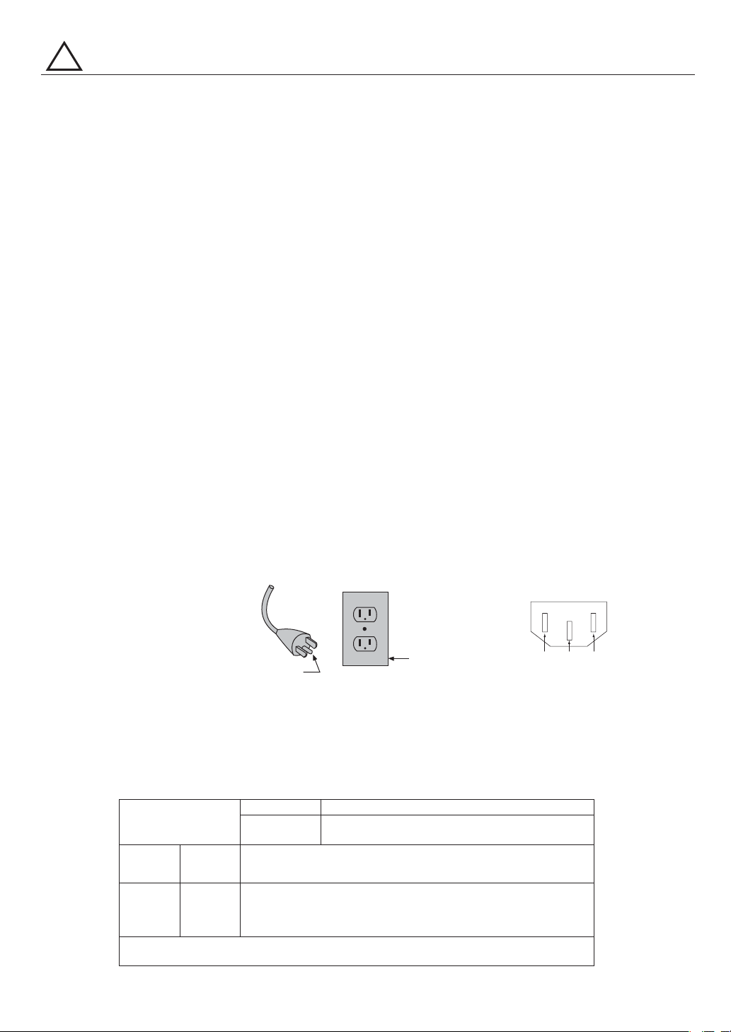
7.ThistoolisintendedforuseonacircuitthathasanoutletthatlooksliketheoneillustratedinSketchAin
Figure(below)(115V).ThetoolhasagroundingplugthatlooksliketheplugillustratedinSketchAinFigure
(below).
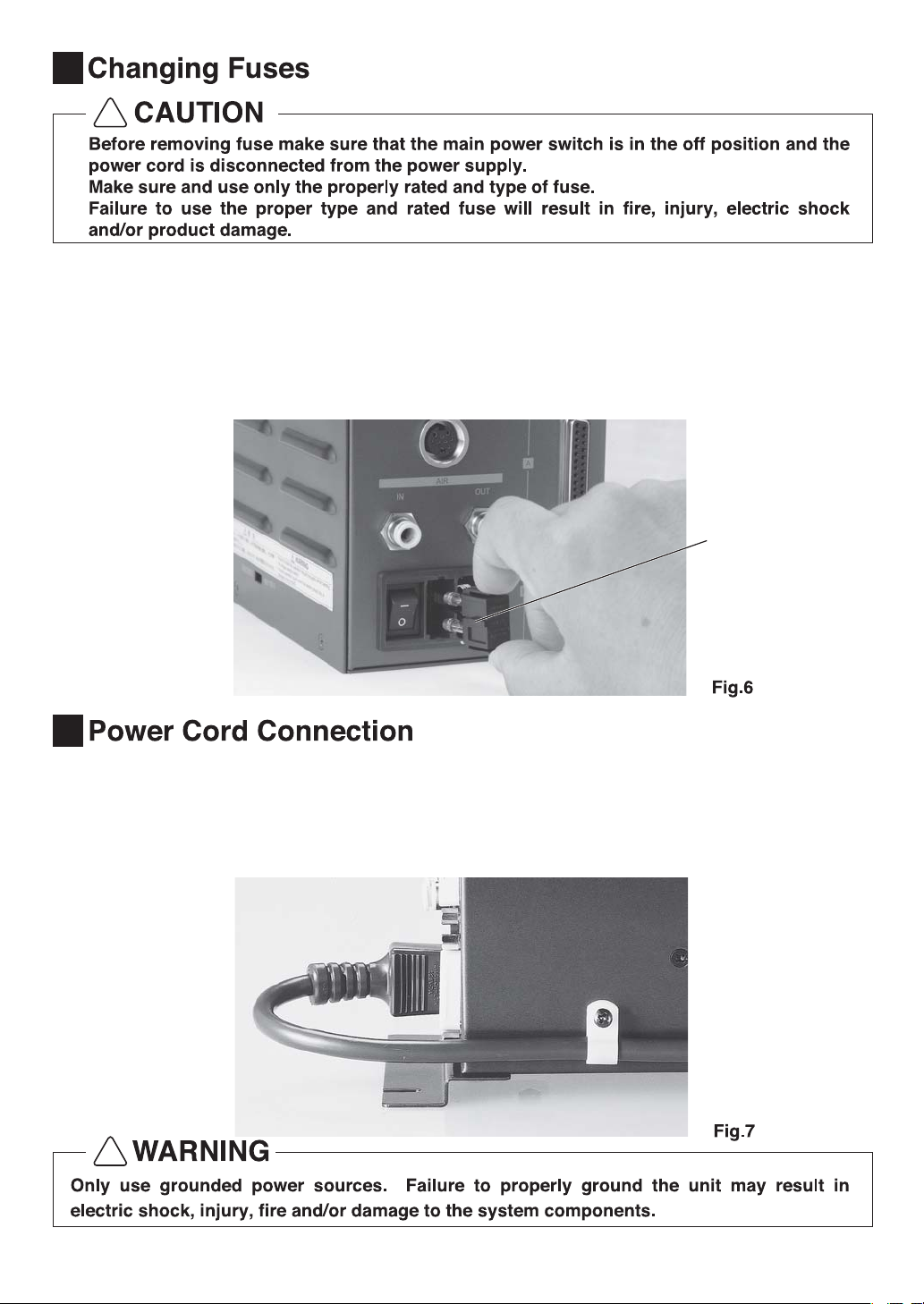
8.ForInstallationinMachineElectricalCabinetorwhenwiringdirectrytomachineinternalpowerterminalstrip:
1)Preaserefertothepindiagrambelowfortheproperwiringconfiguration.Theplugshownisthefemaleplug
thatattachestotheE2530mainpowerinlet.
2)Makesureyoutesteachindividualwiretoverifypropercircuitpriortoattachinganywiretotheterminal
block.Donotassumewirecolorsarethesameforallpowercords.
9.Installanovercurrentprotectivedeviceofmaximum10Ampon
theE2530mainpowercircuit.
10.USEPROPEREXTENSIONCORD.Makesureyourextensioncordisingoodcondition.Whenusingan
extensioncord,besuretouseoneheavyenoughtocarrythecurrentyourproductwilldraw.
Anundersizedcordwillcauseadropthelinevoltageresultinginlossofpowerandoverheating.
Table(below)showsthecorrectsizetousedependingoncordlengthandnameplateampererating.
Ifindoubt,usethenextheaviergage.Thesmallerthegagenumber,theheavierthecord.
!
GROUNDING
PIN
(A) (B)
COVEROFGROUND
OUTLETBOX
GroundingMethod Powercordconnector
AmpereRating
More
Than
Not
More
Than
0
6
10
12
6
10
12
16
Volts
120V
240V
Totallengthofcord
7.5m(25ft.)
15m(50ft.)
15m(50ft.)
30m(100ft.)
30m(100ft.)
60m(200ft.)
45m(150ft.)
90m(300ft.)
18
18
16
14
16
16
16
12
16
14
14
14
12
12
NotRecommended
OnlytheapplicablepartsoftheTableneedtobeincluded.Forinstance,
a120-voltproductneedincludethe240-voltheading.
Minimumgageforcord
LEN
L : Line
N : Neutral
E : Earth

2
1
■Readthesecautionscarefullyandonlyuseinthemannerintended.
■Safety instructions are intended to avoid potential hazards that could result in personal injury or
damage to the device. Safety instructions are classified as follows in accordance with the
seriousnessoftherisk.
ThankyouforpurchasingtheUltra-Precision,High-Speedspindlesystem,E2530.TheE2530System
wasdesignedforuseonCNClathes,robots,NClathesandspecialpurposemachines.Themotor,
spindleandcontrolunit aredesignedtoworkasan integratedsystemcapableof5,000-30,000min
−
1.
Thissystemutilizes air to cool themotorandprotectthespindle, please use an airlinekittoensure
clean,dry,properlyregulatedairissuppliedtothemotorandspindle.TheE2530systemiscapableof
beingusedwithcoolantsandcuttinglubricants.
PleasereadthisOperationManualcarefullypriortouse.
!
①
②
③
④
⑤
⑥
⑦
⑧
!
!
!
①
②
③
④
⑤
⑥

3
⑨
⑩-1
⑪
⑫
⑬
⑭
⑮
3
Input
※Note1
Output
※Note1
Model
Input
Output
OperatingTemperature
AmbientHumidity
OverVoltageCategory
PollutionDegree
SpeedRange
Control
Signal
ProtectionCircuits
Dimensions
Weight
ControlUnit
AC115V/230V,50/60Hz,1PHASE,1.0A/0.5A
AC12V,3PHASE,2.8A
0-40℃
MAX.85%
Ⅱ
2
5,000-30,000min
−
1(500min
−
1forcenteringonly)
TransistorActivationConnections:5
AnalogConnections:2
TransistorActivationConnections:9
AnalogOutputConnections:3
3.6kg
W108㎜×D156㎜×H175㎜
Over-Voltage,Over-Current,OverLoad,SensorMalfunction,Overheat,Brake
Malfunction,SpindleLock,LowAirPressure,Start-UpError,Over-Speed
NE236
2
①TheE2530systemisdesignedto bemountedinaCNClathe,robot,NClathe or specialpurpose
machinefordrilling,milling,slitting,grindingorothersimilarapplication.
②Ahigh-speedbrushlessmotorisusedtoachieveamaximumspeedof30,000min-1andeliminatethe
nuisanceofbrushmaintenance.
③Speedcontrolandprotectionfunctionsutilizeahighperformancemicroprocessor.
④Automaticcontrolandmonitoringofspindlefunctionsarepossible.
⑤Widespeedrange,5,000-30,000min-1makeshighprecisionmachiningpossible.
⑥Compactcontrolunitdesignallowseasyinstallationinspacerestrictedmachines.Connectorsand
controlpanelarefrontmountedforeasyaccess.
⑦Control Unit is capable of being connected to 120V or 230V power sources. The control unit
incorporates a voltage selection switch; make sure this switch is set to the proper position for the
voltagebeingused.
※Note1:ProtectivelySeparated
・PowerCord・AirHosewithFilter・ConnectorCap・ConnectorCoverA・ConnectorCoverB
・Bracket(2pcs.)・NylonTensionRelief・Screw(7pcs.)・OperationManual
StandardAccessories

4
4
※Outputcurveshownis
intermittentuseCurve
−
13
MotorSpeed(x10min)
Torque(cN・m)
Output(W)
E2530Characteristics
Output
IntermittentUseArea
ContinuousUseArea
Torque
Torque
7
2
3
0
4
5
2010
140
120
100
80
60
40
20
0
1
30
6
②
①
③ ④
⑤
⑥
⑦
⑩
⑧
⑨
5
(1)System
①Unit(NE236Shown)
②PowerSwitch
③FuseHolder
④MainPowerInlet
⑤ControlPanel
⑥MotorConnector
⑦AirInputJoint
Supply clean, dry, regulated air for motor cooling.
Regulate air to between 0.15MPa-0.25MPa. Air
mustbesuppliedtooperatethesystem.
⑧Coolingairoutputjointformotor
Connect 4㎜ air hose from motor to output joint
using4㎜to6㎜adaptor.
Ifthispositionisnotbeingused,pleaseinstallthe
airplugtopreventcontamination.
⑨Input/OutputConnectorA
Connector for automatic control and monitoring of
motor/spindlesystem.
Whennotinusepleaseinstalltheconnectorcover
to prevent damage or contamination of connector
orpins.
⑩Input/OutputConnectorB
Whennotinusepleaseinstalltheconnectorcover
to prevent damage or contamination of connector
orpins.

5
(2)ControlPanel
⑪
⑫
⑬
⑭
⑱
⑳
⑲
@1
⑯ ⑮
⑰
⑪DigitalSpeedIndicator(Speed)
Preset Speed, Actual Speed, Warning and Error
Codesaredisplayedto2digits.Whenthemotoris
stopped the Preset Speed is displayed, when the
motorisrotatingtheactualspeedisdisplayed.The
displayalsodisplaystheerrorcodeswhenanerror
hasoccurred.
⑫Speedadjustmentknob
Steplessly adjustable speed control. Rotating the
knobclockwisewillincreaserotatingspeed.Speed
isadjustablefrom5,000-30,000min-1.
⑬StartSwitch
Startsandstopsmotorrotation.
⑭Forward/ReverseSwitch
Right hand rotation(FWD) and left hand
rotation(REV) are as viewed with the cutting tool
facingtheoperator.Withthecuttingtoolfacingthe
operatorrighthandrotation(FWD)willbeclockwise
rotation.
⑮ControllerSwitch(Auto-Manual)
This switch selects motor/spindle control from the
ControlPanelorfromanexternalsource.
●MANUAL:ControlPanel
●AUTOqq:Externalcontrolthrough
theinput/outputconnector.
⑯CenteringModeSwitch(500min-1)
This switch activates the centering mode, which
maintains a constant 500min-1 spindle speed for
centeringthetool.
⑰ResetSwitch(Reset)
This switch resets and allows restarting of the
motor/spindle after an error has been corrected.
Someerrorcodeswillnotallowtheunittobereset
untilafterthepowerswitchhasbeenturnedoff.
⑱LoadMonitorLED(Load)
Themotor/spindleloadisdisplayed by6LED,s (3
Green,2Yellowand1Red).Continuousoperation
ispossiblewithuptoall3greenLED,slit.Ifoneof
theyellowLED,sislitthemotor/spindlecanonlybe
runforashorttime.PleaserefertoSection⁄5 part
4ofthismanualforallowabledurationofhighload
operation.

6
6Diagrams
ControlUnitDiagram
Fig.3 Fig.4
When any of the yellow or red LEDs are lit the
warningLED(Warning)⑳willflash,ifthiscondition
iscontinuedbeyondtheallowableintervaltheerror
LED(Error)⑲willflash andthemotor/spindle will
beshutdown.
⑲ErrorLED(Error)
When a serious problem with the system is
detectedthisLEDblinks,the motor/spindleisshut
down and the Digital Speed Indicator ⑪ displays
theerrorcode.
⑳WARNINGLED(WARNING)
Theoperatingandworkingconditionsofthesystem
are constantly monitored and the warning LED
blinks when a hazardous condition has been
detected.Whenahazardousconditionisdetected
the warning LED blinks and the Digital Speed
Indicator ⑪ alternates between the warning code
and the actual or preset speed, depending on
whetherornotthemotor/spindleisrotating.
@1RotatingLED(RUN)
WhenthemotorisrotatingthisLEDwillflash.
Mountingbracketsareprovidedformountingthecontrolunit.
Thecontrolunitcanbemountedeitherverticallyorhorizontally.
PleasereviewthemountingcautionsonP9⁄00priortomounting
thecontrolunit.
Bracketsinstalled
onthebottom
207.6
193.8
25 20
219.8
68
108
174.8
25 25
156
174.8
10
206
10 156
108
4.5
4.5
68
Bracketsinstalled
ontherear

7
7
・TheControlUnitiscompatiblewith120V-230Vmainsupplyvoltageandisequippedwithaswitchfor
voltageselection.
・Beforeconnectingthecontrolunittothepowersupply,pleasecheckthemainfusesandverifythat
theyarecompatiblewiththevoltagebeingsupplied.Pleaserefertotheflowchartbelowforvoltage
switchingprocedures.
!
!
200/230V 100/115V
200/230V 100/115V
SwitchthemainpowerswitchonthecontrolunittoOFF
Disconnectthemainpowercordfromtheelectricaloutlet
InputVoltageSupply120V InputVoltageSupply230V
Fuse:T3.15A(250V)
OrderNo.U195-152 Fuse:T1.6A(250V)OrderNo.U197-152
MovetheVoltageSelectionSwitch
totherighthandposition
MovetheVoltageSelectionSwitch
tothelefthandposition
Referto,ChangingFuses Referto,ChangingFuses
Concave Concave
※SwitchLocationDiagram
・Thevoltageselectionswitchis
locatedonthelower,rearportion
oftheleftsidepanel.
・Pleaseuseastandardscrew
drivertochangetheselector
switchposition.

8
8
9
・
・
・
!
!
・Pushontheclipsonthetopandbottomofthefuseholderandremovethefuseholderandfuses.
・Removethebadfuseorfusesandreplacewiththepropertypeandratingoffuseaslistedbelowand
determinedbytheinputvoltagebeingused.
Therearetwodifferenttypesoffusesdependingontheinputpowersourcevoltage.
115V T3.15A(250V)U195-152
230V T1.6A(250V)U197-152
・Replacethefuseholdercontainingthefusesintothefuseinletboxandmakesureitsnapsinplace.
・Insertthefemaleplugintothemainpowerinletbox④inthefrontoftheunit.
・Ascrewholeisprovidedonthelower,rightsideofthecontrolunitforattachingthetensionrelief.
UsetheprovidedNylonTensionRelieftoattachthepowercordtothesideofthecontrolunit.
cap

9
10
・
・
!
・Twomountingbracketsareprovidedwiththesystem.
・Thebracketscanbeinstalledonthebottomoronthebackofthecontrolunit.
・Afterinstallingthebracketsyoucanusethescrewcutoutstomountthecontrolunit.
・Attachthebracketsusingthesixholeson
thebottomoftheunitusingtheprovided
screws.
・Attachthebracketsusingthesixholeson
thebackoftheunitusingtheprovided
screws.
①BottomInstallation
Wheninstalling2ormorecontrolunitsinthemachinecabinetmakesuretocheckthateachsingle
controlunithastheproperclearanceonallsides.
③ProperClearance
Bracket
②BackSideInstallation
Bracket
20㎜20㎜
30㎜
30㎜30㎜
30㎜ 30㎜ 30㎜ 30㎜
30㎜

10
12
・
・
・
!
・Inserttheprovidedφ6㎜filteredairhosefromtheAL-0201airlinekitintotheinletjoint⑦onthe
frontofthecontrolunit.(IfyouarenotusingtheAL-0201airlinekit,makesurethattheincoming
airsupplyisdry,cleanair.)
・Insertoneendoftheprovidedφ4㎜coolingairhoseintothebackofthemotor.
・
Inserttheotherendoftheφ4㎜
coolingairhoseintotheoutputjoint⑧onthefrontofthecontrol
unitusingtheprovided6㎜to4㎜adaptor.
・Regulateairpressurebetween0.15-0.25MPa.
11
・AligntheguidepinAonthemotor
plugwiththekeywayBonthemotor
socketonthefrontofthecontrolunit.
・ScrewinthecouplingnutCofthe
motorplugtothemotorsocketDon
thefrontofthecontrolunit. C
D
AB
⑦ ⑧
AirHosewithfilterAirHosewithfilter
Reducer
(φ6
―
φ4)
Reducer
(φ6
―
φ4)
AirHoseforthecoolantofmotor
(Outsidediameterφ4㎜,length4m)
AirHoseforthecoolantofmotor
(Outsidediameterφ4㎜,length4m)

11
13
(1)Selectingcontrolmode
・Usingthecontrolswitch(⑮in )youcanselectbetweenManual(FrontPanelControl)orAuto
ExternalSignalSourcecanbeusedtocontrolMotorStart/Stop,RotationalDirection,
500min-1centeringrotation.
・ManualMode-FrontPanelOperation.
・AutoMode-ControlbyExternalSignalSource.
(2)RotationDirection,500min-1centeringrotation,MotorStart/Stop.
①ManualControlMode
・Setrotationdirection Pushtherotationaldirectionswitch⑭
・Select500min-1centeringrotation
Pushthe500min-1switch⑯
(Neveruse500min-1rotationforcutting,thismodeisonlyfor
centeringonamachiningcenter)
・MotorStart/Stop PushStartswitch⑬,the'Start'LEDwilllightandthespindlewill
rotate.PushtheswitchagaintostopthespindletheLEDwillturnoff
andthespindlewillstoprotating.
⑮ControlSwitch
⑯500min-1Switch
⑭RotationaldirectionSwitch
⑬StartSwitch
②AutoControlMode
UsetheInput/OutputConnectorA⑨toinputcontrolsignalstotheunit.
・Setmotorrotatingdirection InputthemotorrotatingdirectionsignaltoPinNo.2:DIRIN
RighthandrotationisOFF'Open'("F.W.D"LEDwilllight)
LefthandrotationisON'Closed'("R.E.V"LEDwilllight)
・Set500min-1rotation InputthecenteringrotationsignaltoPinNo.16:500min-1
500min-1LEDwilllight
Neveruse500min-1centeringrotationforcutting

12
・MotorStart/Stop InputthemotorstartsignaltoPinNo.14:START
MotorrotatingisON'Closed'(STARTLEDwilllight)
MotorstoppedisOFF'Open'(StartLEDisOff)
IfthemotorstartsignalisON'Closed'andthepowerswitchis
turnedonorthecontrolmodeischangedfromMANUALto
AUTOerrorcode'EA'willbedisplayed.Thisisasafetyfeature
topreventunintendedrotation.
(3)SettingMotorSpeed
①ControlModeissettoMANUAL
SetthespeedbyrotatingtheSPEEDKnob⑫.Clockwiseincreasesspeed,counterclockwise
decreasesspeed.
・MotorSpeedRangeis5,000-30,000min
−
1.
Iftheairpressureistoolowthecontrolunitwillnotoperate.
・Themotorspeedisdisplayedin1,000min-1.30equals30,000min-1
⁄9
・ ・ ・
・ ・
!
⑫Knob
②ControlModeissettoAUTO
InputExternalSignalSourcetoInput/OutputConnectorA⑨
・MotorrotationspeedissetbyvoltageinputtoMotorSpeedControlSignal(PinNo.23:VR1)
・0VDCequals5,000min-1andmorethan8VDCequals30,000min-1.
・Themotorspeedisdisplayedin1,000min-1.30equals30,000min-1.
(4)SettingotherMotorSpeedParameters
ThefollowingMotorSpeedParameterscanalsobepreset.
・Fixthemotorspeedofmotor.
・Setthemaximummotorspeedofmotor.
・WhenusingAUTOcontrolmodethemotorspeedofmotorcanbeseteitherelectronicallyorbythe
potentiometeronthefrontpanel.
・MotorStartCommandSignalMethod
・AirInputmonitoringoverride
・IfanerroroccursanerrorsignalisoutputtotheInput/OutputConnectors.Thedefaultsettingis
ON('Closed')andOFF('Open'),thissettingcanbereversedifdesired.PleaserefertotheSettingof
Parameterssectionofthismanualfordetailsonreversingthesesignals.

13
14
①OutsideINPUT-OUTPUTConnectorSignalDetail
(1)Input/OutputConnectorA
Pin
No. PinName Description Input/
Output Signal Function
※1Theerrorsignaloutputcanbereversed.Pleaserefertothesettingofparameterssectionofthismanual.
※2
・
・
!
1 COM(+)
2 DIRIN
3 −
4 RESET
5 −
6 RUN
7 DIROUT
8 ERR
9 −
10 GND
11 VCC
12 MOTORI
13 GND
14 START
15 −
16 500min-1
17 OPIN
18 COM(-)
19 PULSE
20 WARNING
21 COIN
22 −
23 VR
24 LOAD
25 SPEEDV
24VDCPowerSourcefor
ExternalControlInputs
Rotationdirected
signal
NotUsed
ErrorReleaseSignal
NotUsed
RotatingSignal
RotatingDirection
Signal
ErrorSignal
NotUsed
PowerSourceGND
10VDCPowerSourcefor
ExternalControlInputs
MotorCurrentMonitor
PowerSourceGND
RotateCommand
Signal
NotUsed
RotatesMotorat
CenteringSpeed
ReservedSignal
ExternalPowerSourceGND
RotatingPulse
WARNINGSignal
SpeedAchievement
Signal
NotUsed
MotorSpeedControl
Signal
TorqueLoadMonitor
RotatingSpeed
MonitorVoltage
PowerSourcetobeusedforExternalInputs.+24Vor0V
DC(*2).
Controlsthedirectionofrotationofthemotor.
NotUsed
Errorcodecanbereleasedandthesystemrestartedby
switchingthissignalOFFandON.
NotUsed
Voltageoutputshowsthatthemotorisrotating.
Voltageoutputshowsthedirectionthemotorisrotating.
Errorhasoccurred.(*1).
ErrorCodeisdisplayedontheDigitalSpeedDisplay.
NotUsed.
InternalGround(*2).
PowerSourceforExternalSpeedControlSignal.
VoltageOutputshowsthemotorcurrentconsumption.
Outputvoltageisproportionaltothemotorcurrent
consumption.
InternalGround.
StartsandStopsmotorrotation.
NotUsed
Maintainsconstant500min-1motorspeedforcentering
ReservedSignalDONOTUSE
ConnecttoGNDofexternalPowerSource
1revolutionofthemotorgeneratesonepulse.Duty50%
ThisoutputshowsaWARNINGhasoccurred.The
WARNINGCodeisshownontheDigitalSpeedIndicator
Voltageoutputshowsthatthemotorhasachievedmore
than90%ofthesetspeed.
NotUsed
SetsrotatingspeedofMotor
VoltageOutputisproportionaltothemotorspeed.
Voltageoutputshowsthetorquebeingappliedtothe
motor.Loadmonitorvoltagex20equalsthetorqueload%.
20V=Load%
VoltageOutputisproportionaltothemotorspeed
Input
Input
−
Input
−
Output
Output
Output
−
Output
Output
Output
Output
Input
−
Input
−
Input
Output
Output
Output
−
Input
Output
Output
+24Vor0VDC
OFF(Open):FWD
ON(Closed):REV
ON(Closed)
OFF(Open)
ON(Closed):MotorRotating
OFF(Open):MotorStopped
OFF(Open):FWD
ON(Closed):REV
ON(Closed):Normal
OFF(Open):Error
InternalGND
+10VDC
0-10VDC
0V:0A
10V:20A
InternalGND
ON(Closed):Rotation
OFF(Open):Stop
ON(Closed):500
min-1
OFF(Open):NormalOperation
−
ExternalGround
1pulse/rotation
OFF(Open):NormalOperation
ON(Closed):WARNING
ON(Closed):Ordered
SpeedAchieved
OFF(Open):Ordered
SpeedNotAchieved
0-10VDC
0V:5,000min-1
8V:30,000min-1
0-10VDC
0V:0%
10V:200%
0-10VDC
1V:10,000min-1
3V:30,000min-1

14
②Input/OutputSignals
●InputSignal
Thereare4kindsofinputsignals:rotationcommand,rotationdirection,500min-1speedcommand.
Thesesignalsare+24VDcsignalsfromanexternalsignalsource.
Pleaseuseaseparatepowersourcethatiscapableofsupplying24VDC±10%,20mA(5mA/circuit).
RefertoFiguresbelowforconnections.
+24V
1
0V
1
Thesideofunit Thesideofunit
COM:+24V
PIN1(COM)connectedto+24VDC PIN1(COM)connectedto0VDC
COM:0V
+24V
Thesideofunit
R
R
18
−
COM:0V
●OutputSignal
Thereare6kindsofoutputsignals:rotating,rotatingdirection,rotatingpulse,rotatingspeed
achieved,warning,anderror.Thesesignalsarepulsedtransistoractivationsignals.
VoltageandCurrentSpecifications
AppliedVoltage(Vmax)≦30VDC
WorkingCurrent(Ip)≦100mA(RotationalPulse50mA)
Useanexternalpowersourceforoutputcircuits.Itisrecommendedtousethesame24VDCpower
sourceusedforinputsignals.Pleasereferto forconnections.

15
●MotorSpeedControlSignal
RefertoFig.21forconnections.
Fig.21
0V
10
11
Potentiometer
5KΩ
23
Thesideofunit
10VDCPowerSourcefor
ExternalControlInputs
MotorSpeedControlSignal
●MonitoringSignals
Thereare3kindsofanalogmonitoringsignals:
MotorCurrent,TorqueLoadMonitorandRotating
SpeedMonitor.PleaserefertoFig. 22for
connections.
Fig.22
Thesideofunit
V
V
V 1KΩ
1KΩ
1KΩ
0V
13
25
24
12 MotorCurrent
Monitor
TorqueLoad
Monitor
RotatingSpeed
MonitorVoltage
Pin
No.
PinName
Description Input/
Outpu Signal Function
1 −
2 MT
−
CNA
3 −
4 −
5 AUTO+
6 PWON+
7 −
8 −
9 −
10 MT
−
CNB
11 −
12 −
13 AUTO
−
14 PWON
−
15 ―
NotUsed
MotorSignalConnect
ContactA
NotUsed
NotUsed
AUTOMode
Signal(+)
UnitPowerSource
Monitor(+)
NotUsed
NotUsed
NotUsed
MotorSignalConnect
ContactB
NotUsed
NotUsed
AUTOModeSignal(-)
UnitPowerSource
Monitor(-)
NotUsed
Whenthereiscontinuity,OFF,betweenPIN2andPIN10the
motorisconnected,ifnocontinuitythemotorisdisconnec-
tedorthemotorcordisbroken.
NotUsed
NotUsed
NotUsed
WhenAUTOModeisbeingusedthisPinisON(Closed)
NotUsed
Ifthemainpowersupplytotheunitisconnectedthisoutput
isON(Closed)
Whenthereiscontinuity,OFF,betweenPIN2andPIN10the
motorisconnected,ifnocontinuitythemotorisdisconnec-
tedorthemotorcordisbroken.
WhenAUTOModeisbeingusedthisPinisON(Closed)
Ifthemainpowersupplytotheunitisconnectedthisoutput
isON(Closed)
NotUsed
NotUsed
NotUsed
NotUsed
NotUsed
Continuity,OFF(Open),
betweenPIN2andPIN10
themotorisconnected.
AutoModeOperation
ON(Closed)
ON(Closed):MainPowerSup-
plyisconnected
OFF(Open):MainPowerSup-
plyisdisconnected
Continuity,
OFF(Open)
,
betweenPIN2andPIN10
themotorisconnected.
AutoModeOperation
ON(Closed)
ON(Closed):MainPower
Supplyisconnected
OFF(Open):MainPower
Supplyisdisconnected
Output
Output
Output
Output
Output
Output
・When using 0V DO NOT connect to PIN10 or 13(Internal Ground) of Input/Output
Connector A.
!
※1
(2)Input/OutputConnectorB
①OutsideINPUT-OUTPUTConnectorBSignalDetails
Caution

16
+24V
0V
TheSideofunit
13
10
2
5
0V
R
②Input/OutputSignals
●OutputSignal(PINNo.2-10,5-13,6-14)
Thereare3kindsofoutputsignals:MotorSignalConnectDetector,AUTOMODEandUnit
PowerSourceMonitoring.
Thesesignalsarepulsedtransistoractivationsignals.
VoltageandCurrentSpecifications
AppliedVoltage(Vmax)≦30VDC
WorkingCurrent(Ip)≦100mA(RotationalPulse50mA)
Useanexternalpowersourceforoutputcircuits.Itisrecommendedtouseaseparatepowerfrom
theoneusedforInput/OutputConnectorA.Pleasereferto forconnections.
R
R
0V
14
6R
(3)Input/OutputSignalConnectorSpecifications
Input/OutputConnectorA
PlugPartNumber:XM2A-2501OMRON(orothersimilarhigh-qualityproduct)
CoverPartNumber:XM2S-2511OMRON(orothersimilarhigh-qualityproduct)
Input/OutputConnectorB
PlugPartNumber:XM2A-1501OMRON(orothersimilarhigh-qualityproduct)
CoverPartNumber:XM2S-1511OMRON(orothersimilarhigh-qualityproduct)
・ThePlugandCoverarenotprovidedwiththesystem.Pleasepurchasethespecifiedplugandcover
fromlocalsuppliers.
・UseonlyshieldedcablestominimizeRFinterferenceandnoise.Connecttheshieldtotheplugcover.
・Differentmakersusedifferentnamesforthecover.
!

17
15
(1)WARNINGFunction
Alwayscheckthecontrolunit,motor,spindleandtheconditionofthecoolingairpriortouse.This
willhelppreventsystemerrorsthatwillresultinundesiredoperatingconditions.
・TheWARNINGLED⑳willflash.
・TheWARNINGCode(listedinTable1)willbedisplayedontheDigitalSpeedIndicator⑪.
・A WARNING Signal is output to the WARNING Signal(PIN No. 20:WARNING) of Input/Output
ConnectorA.
Note:WhenusingtheInput/OutputConnectorandexternalmonitoring,pleasecheckandresolvethe
sourceofthetroubleanytimeaWarningCodeisdisplayed.
WARNINGCode
A0
A1
A3
WarningFunction
MotorCord
LowAirPressure
OverLoad
Trouble
MotorCordorConnectorisdisconnectedormisaligned
LowAirPressure
MotorTorqueloadexceedingsafelimits
(2)Detectionofunsafeoperatingconditions
Alwayscheckthecontrolunit,motor,spindleandtheconditionofthecoolingairpriortouse.This
willhelppreventsystemerrorsthatwillresultinundesiredoperatingconditions.
・Motorstops
・TheErrorLED⑲willflash.
・ErrorCode(listedinTable2)willbedisplayedontheDigitalSpeedIndicator⑪.
・AnErrorsignalisoutputtotheErrorSignal(PINNo.8:ERR)ofInput/OutputConnectorA.
Table1
(4)Input/OutputConnectorA,BPinConfiguration
1
2
3
4
5
6
7
8
9
10
11
12
13
14
15
16
17
18
19
20
21
22
23
24
25
1
2
3
4
5
6
7
8
9
10
11
12
13
14
15
ConnectorA ConnectorB

18
(3)ResettingSystemafterErrorCodes
Thereare2methodsofreleasingerrorcodes.
・PushErrorResetSwitch⑰ RESETonthefrontpanel.
・SwitchthesignalonPIN4(RESET)ofInput/OutputConnectorAOFF(Open)-ON(Closed)-
OFF(Open).
(4)TorqueOverload
WhentheLoadMonitorLED(Load)⑱lights4ormoreLEDs(3greenLEDsand1ormoreyellow
LEDs)anoverloadconditionexists.Duringoverloadoperationthefollowoccurs.
・WARNINGLED(Warning)⑳ flashes
・WARNINGCodeA3isdisplayedontheDigitalSpeedIndicator⑪
・WARNING
SignalisoutputtotheWARNINGSignalPIN20(Warning)ofInput/OutputConnectorA
Overloadoperationisconsideredshorttermoperationmode.Theallowableoperationtimedepends
onthenumberoflightedLEDsontheLoadMonitorLED(Load)⑱.Theallowabletimeisdetailed
below.
・LoadMonitorLED4LEDs:40Seconds
・LoadMonitorLED5LEDs:20Seconds
・LoadMonitorLED6LEDs:10Seconds
Whentheallowabletimeisexceededthemotorwillstopandthefollowingoccurs.
・ErrorLED(Error)⑲flashes
・ErrorCodeE8isdisplayedintheDigitalSpeedIndicator⑪.
・ErrorSignalisoutputtotheerrorsignalPIN8(ERR)ofInput/OutputConnectorA.
ErrorCode
E1
E2
E3
E4
E5
E6
E7
E8
E9
EA
EC
EH
ProblemArea
ExcessCurrent
Overvoltage
MotorSensor
ControlUnitOverheat
BrakeCircuitTrouble
RotorLock
LowAirPressure
TorqueOverload
TroublewithPowerSource
ExternalControlSignalError
InternalMemoryError
OverSpeed
Trouble
MotorCurrentbeyondsafelimits.
MotorVoltagebeyondsafelimits.
Troublewiththesensorsignalinthemotor.
InternalTemperatureoftheControlUnittooHigh.
Troublewiththemotorbrakecircuit.
Motorstalledformorethan3seconds.
Inadequateairsuppliedformorethan4secondsduringrotation
orinadequateairsupplywhenmotorstartcommanded.
Torquelimitsexceededfortoolongaperiodoftime.See(4)onPage24.
Troublewiththepowersourceinsidethecontrolunit.
Externalcontrolsequencingproblem.
Troublewithmemory(EEPROM).
Rotatingspeedisbeyondthesetspeedfortoolong.
Note:・WhenusingtheInput/OutputConnectorandexternalmonitoring,pleasecheckandresolve
thesourceofthetroubleanytimeaWARNINGCodeisdisplayed.
・ThefollowingErrorCodescannotbereleased:E4(ControlUnitOverheat),E5(BrakeCircuit
Trouble),E9(TroublewithPowerSource),EC(InternalMemoryError).Oncethesourceof
theerroriscorrected,turnthesystemoffandtheErrorCodewillbereleasedwhenthe
systemisturnedon.
!
Table2

19
16
TheE2530isahigh-precision,high-speedmotor-spindle,thefollowingproceduremustbefollowedto
ensureproperoperationandlongevity.
During transportation, storage or installation the grease inside the bearings will settle. If the
motorspindle is suddenly run at high-speed excessive heat will cause bearing damage. After
installation, repair, initial operation, or long periods of non operation please follow the break-in
proceduredetailedinTable3.
2
10,000
10min
SpindleHousingno
hotterthan20℃.If
hotterthan20℃
checkinstallation
andrestartBreak-In
procedure.
SpindleHousingno
hotterthan20℃.If
hotterthan20℃stop
foratleast20
minutes,check
installationand
restartBreak-In
procedure.
SpindleHousingless
than20℃.
1
5,000
10min
NoAbnormalNoises
3
20,000
10min
4
30,000
15min
Steps
RPM(min-1)
RunningTime
ItemstoCheck
Table3
17
Trouble Cause Inspect/CorrectiveAction
AbnormalVibration
orNoiseduring
Operation
HighRun-Out
Motordoesnot
reachthepreset
speed
MotorDoesNot
Run
Powerisnotsupplied ChecktheMainPowerInletconnectiononthefront
oftheunit
ControllerSwitchissettoMANUALbuttrying
tostartwithanexternalcommandsignalthrough
Input/OutputConnectorA
StartwiththeStartSwitchontheControlPanel,or
settheControllerSwitchtoAuto
ControllerSwitchissettoAUTObuttrying to
startwiththeStartSwitchontheControlPanel
Startwithanexternalcommandsignalorsetthe
ControllerSwitchtoManual
TooloutofBalance Changethetool
ColletNutisnotproperlypositioned Positionthecolletnutproperly
BallBearingsWorn SendtoNAKANISHIforRepair
ForeignParticlesstuckinthecolletchuckorspindle
Cleantheinsideofthecolletchuckandspindle
MaximumMotorSpeedissetintheP4
parameters.
ChecktheP4parametersettingsandadjustas
needed.
MotorFixedSpeedissetintheP3parameters. ChecktheP3parametersettingsand
adjustasneeded.
500min
-1
CenteringRotationModeisselected.
Checkthefrontpanelsettingsandinputon
Input/OutputConnectorA
PINNo.16(500min
-1
)andcorrectasnecessary.
ErrorCodeIndicated CheckandcorrectthesourceoftheErrorCode
LowAirPressure Adjustairpressuretobetween0.15MPa-0.25MPa
MotorCordorConnectorDisconnected ConnecttheMotorCordtotheconnectororcheck
theMotorCable
ForeignParticlesintheballbearings.
BallBearingsWorn
SendtoNAKANISHIforRepair
AutoModeMotorSpeedControlsetting,inthe
'P2'parameters,issettoexternalcommand
signalandtryingtoadjustspeedwith
potentiometerorAutoModeMotorSpeedControl
setting,inthe'P2'parametersissetto
potentiometerandtryingtoadjustspeedwith
externalcommandsignal.
ResettheAutoModeMotorSpeedControl
parameters.
Table of contents