Nakanishi E3200 Series User manual

'09.05.003 A
NE261
E3200 SERIES SELECTOR UNIT
OM-K0582E

1 2
WARNING !
When using electric tools, basic safety precautions should always be followed to reduce the risk of fire, electrical
shock and personal injury, including the following.
Read all these instructions before operating this product and save these instructions.
A. GROUNDING INSTRUCTIONS
1. In the event of a malfunction or breakdown, grounding provides a path of least resistance for electric current
to reduce the risk of electric shock. This tool is equipped with an electric cord with a grounding conductor
and a grounding plug. The plug must be plugged into a matching outlet that is properly installed and
grounded in accordance with all local codes and ordinances.
2. Do not modify the plug provided - if it will not fit the outlet, have the proper outlet installed by a qualified
electrician.
3. Improper connection of the grounding conductor can result in electric shock. The conductor with insulation
having an outer surface that is green with or without yellow stripes is the grounding conductor. If repair or
replacement of the electric cord or plug is necessary, do not connect the grounding conductor to a live
terminal.
4. Check with a qualified electrician or service person if the grounding instructions are not completely
understood, or if in doubt as to whether the tool is properly grounded.
5. Use only 3-wire extension cords that have 3-prong grounding plugs and 3-pole receptacles that accept the
tool's plug.
6. Repair or replace damaged or worn cord immediately.
7. This tool must be used on a circuit that has an outlet that looks like the one illustrated in Sketch A in Figure
(
below
)(
115V
)
. The tool has a grounding plug that looks like the plug illustrated in Sketch A in Figure
(
below
)
.
8. FOR Installation in Machine Electrical Cabinet or when wiring
directly to machine internal power terminal strip:
1) Please refer to the pin diagram below for the proper wiring
configuration. The plug shown is the female plug that attaches
to the NE261 main power inlet.
2) Make sure you test each individual wire to verify proper circuit
prior to attaching any wire to the terminal block. Do not assume
wire colors are the same for all power cords.
9. Install an over current protective device of maximum 10 Amp on
the NE261 main power circuit.
IMPORTANT INSTRUCTIONS AND WARNING - Electric Devices
B. OTHER WARNING INSTRUCTIONS
1. For your own safety read instruction manual before operating tool.
2. Wear eye protection.
3. Replace cracked wheel immediately.
4. Always use guards and eye shields.
5. Do not overtighten wheel nut.
6. Use only flanges furnished with the grinder.
7. REMOVE ADJUSTING KEYS AND WRENCHES. Get in the habit of checking to see that keys and adjusting
wrenches are removed from tool before turning it on.
8. KEEP WORK AREA CLEAN. Cluttered areas and benches invite accidents.
9. DON'T USE IN DANGEROUS ENVIRONMENT. Don't use power tools in damp or wet locations, or expose
them to rain. Keep work area well lighted.
10. Risk of injury due accidental starting. Do not use in an area where children may be present.
11. DON'T FORCE TOOL. It will do the job better and safer at the rate for which it was designed.
12. USE RIGHT TOOL. Don't force tool or attachment to do a job for which it was not designed.
13. WEAR PROPER APPAREL. Do not wear loose clothing, gloves, neckties, rings, bracelets, or other jewelry
that might get caught in moving parts. Nonslip footwear is recommended. Wear protective hair covering to
contain long hair.
14. ALWAYS USE SAFETY GLASSES. Everyday eyeglasses only have impact resistant lenses, they are NOT
safety glasses. Also use face or dust mask if cutting operation is dusty.
15. SECURE WORK. Use clamps or a vise to hold work when practical. It's safer than using your hand and it
frees both hands to operate tool.
16. MAINTAIN TOOLS WITH CARE. Keep tools sharp and clean for best performance and to reduce the risk of
injury to persons. Follow instructions for lubricating and changing accessories.
17. DISCONNECT TOOLS before servicing; when changing accessories, such as blades, bits, cutters, and like.
18. REDUCE THE RISK OR UNINTENTIONAL STARTING. Make sure switch is in off position before plugging in.
19. USE RECOMMENDED ACCESSORIES. Consult the owner's manual for recommended accessories. The use
of improper accessories may cause risk of injury to persons.
20. NEVER LEAVE TOOL RUNNING UNATTENDED. TURN POWER OFF. Don't leave tool until it comes to a
complete stop.
21. For recommended operating speed for various applications, please follow the instructions of bur
manufacturers.
GROUNDING
PIN (A)
COVER OF GROUND
OUTLET BOX
Grounding Method
10. USE PROPER EXTENSION CORD. Make sure your extension cord
is in good condition. When using an extension cord, be sure to use
one heavy enough to carry the current your product will draw.
An undersized cord will cause a drop the line voltage resulting in
loss of power and overheating.
Table
(
below
)
shows the correct size to use depending on cord
length and nameplate ampere rating.
If in doubt, use the next heavier gage. The smaller the gage
number, the heavier the cord.
Minimum gage for cord
Ampere Rating
Volts Total length of cord
120V
240V
More
Than
Not
More
Than
Only the applicable parts of the Table need to be included. For instance,
a 120-volt product need include the 240-volt heading.
0
6
10
12
6
10
12
16
18
18
16
14
16
16
16
12
16
14
14
14
12
12
Not Recommended
7.5m (25ft.)15m (50ft.)30m (100ft.)45m (150ft.)
15m (50ft.)30m (100ft.)60m (200ft.)90m (300ft.)
L : Line
N : Neutral
E : Earth
LEN
Power cord connector
CONTENTS
IMPORTANT INSTRUCTIONS AND WARNING-Electric Devices ..........................................................P.1
CAUTIONS FOR HANDLING AND OPERATION .................................................................................P.3
FEATURES ............................................................................................................................................P.4
SPECIFICATIONS & DIMENSIONS .....................................................................................................P.5
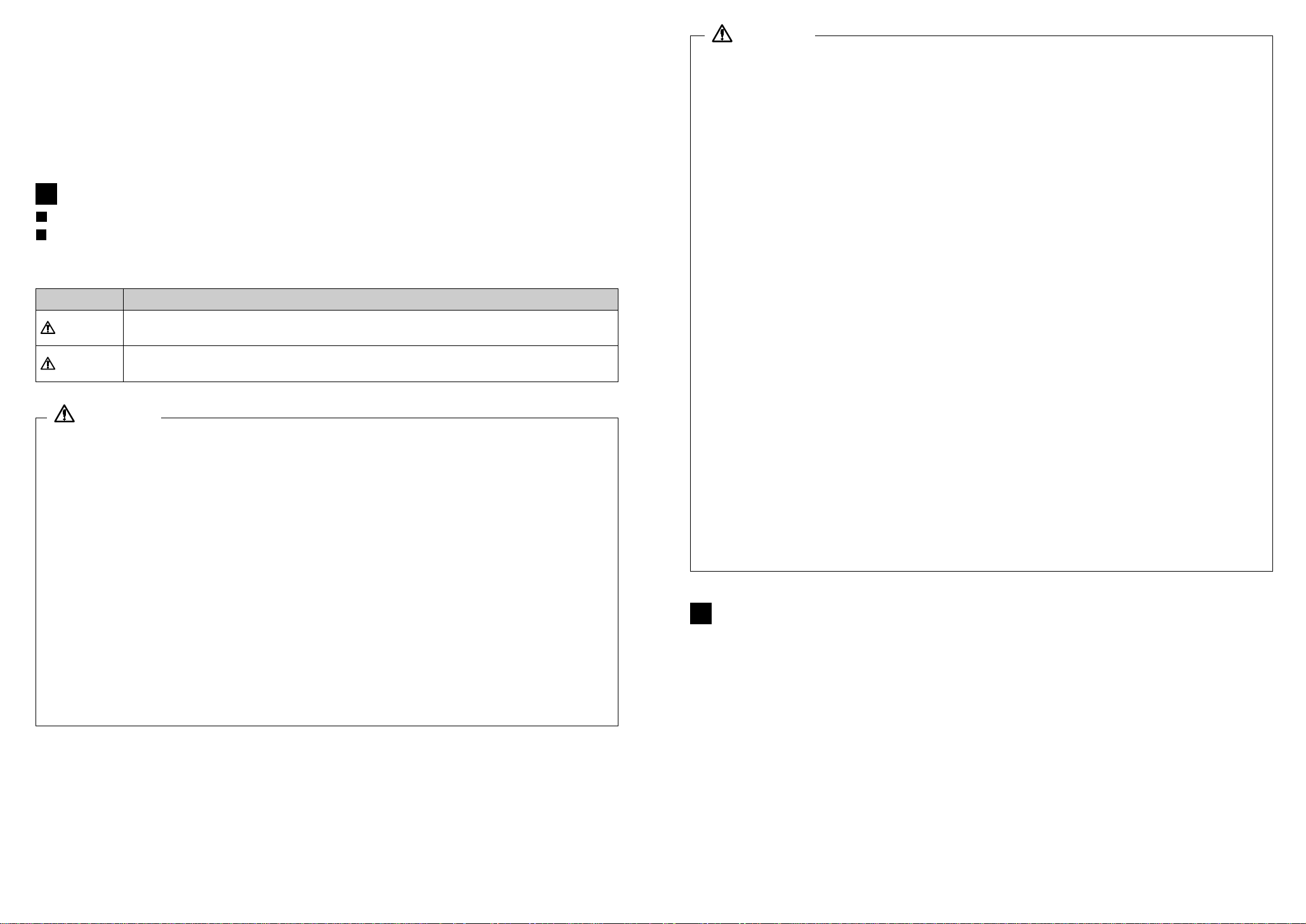
NOMENCLATURE ................................................................................................................................P.6
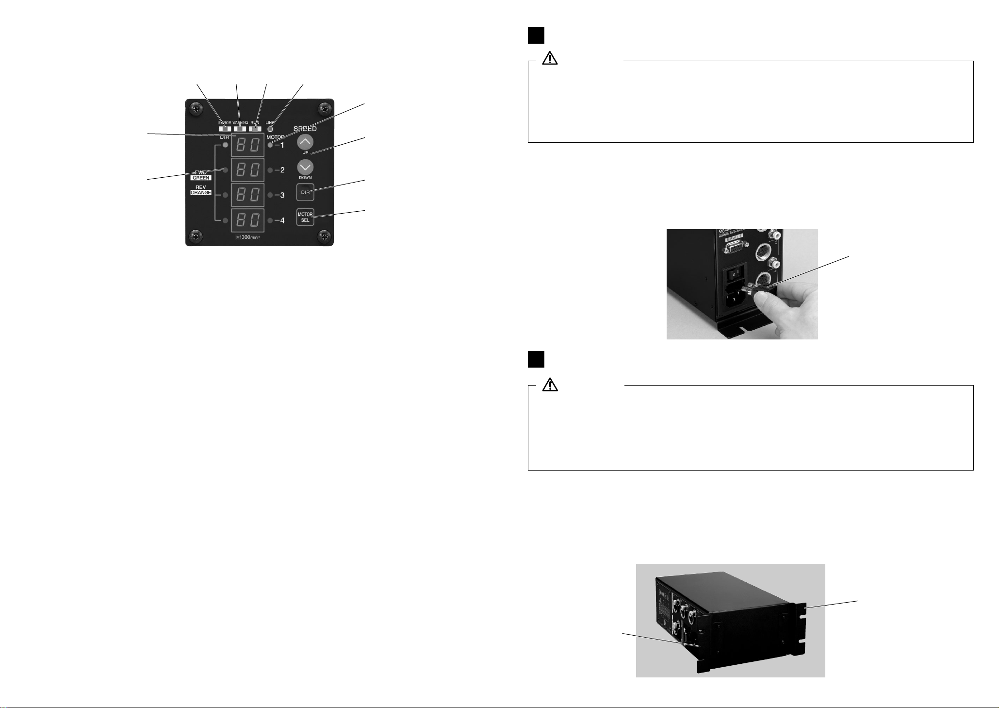
CHANGING FUSES ...............................................................................................................................P.8
BRACKET INSTALLATION ...................................................................................................................P.8
POWER CORD CONNECTION ..........................................................................................................P.10
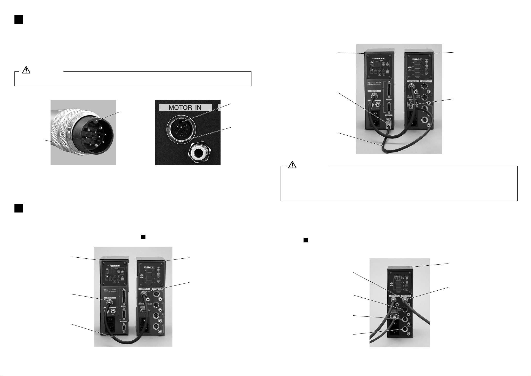
MOTOR CORD CONNECTION ..........................................................................................................P.11
CONNECTING THE CONTROL UNIT (NE260)TO THE SELECTOR UNIT (NE261)
..................................................P.11
OPERATION PROCEDURES ............................................................................................................P.14
EXTERNAL INPUT/OUTPUT CONTROL SIGNAL SPECIFICATIONS
.........................................................P.17
TROUBLE SHOOTING ........................................................................................................................P.22
SYSTEM CHART .................................................................................................................................P.23
3
1
2
4
5
6
7
8
9
10
11
12
13
NE261K0582Ee090509.9.221:26AMページ1

4
1. The E3200 system is designed to be mounted in a CNC lathe, robot, NC lathe or special
purpose machine for drilling, milling, slitting, grinding or other similar application.
2. Up to 4 motors can be connected to NE261 providing individual control of each motor.
(4 motors can’t be run simultaneously)
3. External control signals and external monitoring can be done with the NE260 and NE261
combination. Control and monitoring input and output signals will all be connected to CN1
on the NE260.
4. Wide speed range, 1,000-80,000 min-1 makes high precision machining possible.
5. Compact selector unit design allows easy installation in space restricted machines.
Connectors and control panel are front mounted for easy access.
6. Control Unit is capable of being connected to AC100V to 240V power sources.
FEATURES
2
3
Thank you for purchasing the E3200 Ultra-Precision, High-Speed spindle system. The NE261 was
designed for controlling multiple sequentially controlled spindles on CNC lathes, robots, NC
lathes and special purpose machines. The motor, spindle and control unit are designed to work
as an integrated system capable of 80,000 min-1. This system utilizes air to cool the motor and
protect the spindle, please use an air line kit to ensure clean, dry, properly regulated air is
supplied to the motor and spindle. The E3200 system is capable of being used with coolants and
cutting lubricants. Please read this Operation Manual carefully prior to use.
Read these cautions carefully and only use in the manner intended.
Safety instructions are intended to avoid potential hazards that could result in
personal injury or damage to the device. Safety instructions are classified as follows
in accordance with the seriousness of the risk.
CAUTIONS FOR HANDLING AND OPERATION
1
Class
WARNING
A hazard that could result in bodily injury or damage to the device if the safety
instructions are not followed.
CAUTION A hazard that could result in light or moderate bodily injury or damage to the
device if the safety instructions are not followed.
Degree of Risk
WARNING
1. The E3200 Series is not a hand tool. It is designed to be used on a NC lathe or
special purpose machine.
2. In the event of a malfunction or breakdown, grounding provides a path of least
resistance for electric current, reducing the risk of electric shock. This system is
equipped with an electric cord with a grounding conductor and a grounding plug.
The plug must be plugged into a matching outlet that is properly installed and
grounded in accordance with all local codes and ordnances.
3. Don’t use in dangerous environments. Protect the selector unit from moisture
and other contaminants. Failure to protect the selector unit can result in damage
to internal components and injury to the operator.
4. Always wear safety glasses. Everyday eyeglasses only have impact resistant
lenses, they are not safety glasses. Also use a dust or face mask whenever the
motor is running.
5. Ensure that the earth wire is properly grounded : failure to follow this warning
may result in electric shock or fire.
6. Check to ensure that the supply is the same as the control unit's rated voltage.
CAUTION
1. Motor cooling and Spindle purge air is required to operate the system.
Air hose must be connected to the Air in joint on the front of the control unit.
0.35MPa air must be supplied.
2. When errors occur and error lamp flashes, check and correct the cause of the
malfunction before continuing use. Failure to correct the problem will result in
damage to the unit and motor.
3. When the Warning Lamp on the control unit lights conditions exist that could
result in dangerous operation. Check operating conditions and continue use only
after correcting the problem.
4. Do not hit, drop or subject motor, spindle or control unit to shock as this will
cause damage to internal components and result in malfunctions.
5. The electric motor and spindle require air for cooling and protection : ensure that
this supply is clean, dry air. Introduction of dust, moisture or other contaminants
into the motor and spindle will cause damage to internal components.
6. When using NE260 continuously, refer to Continuous Area on Torque
Characteristics Graph or check the LOAD meter (3 Green Lamps).
7. Do not install system next to RF noise sources as malfunctions can occur.
If smoke, noise or strange odors emanate from the unit or motors immediately
turn off the power switch, disconnect and take to a NAKANISHI authorized
Dealer for service.
8. Stop working immediately when abnormal rotations or unusual vibration are
observed.
9. Do not place anything on NE261. This may cause damage to NE261.
10. Do not disassemble, modify or attempt to repair the unit or motor as it will
damage internal components and there are no user serviceable parts.
11. Attach the connector cap or air plug (Provided) when you don’t use NE261.
12. When installing a motor/spindle to a fixed base, make sure the fixed base is
grounded in order to avoid the risk of an electric shock.
NE261K0582Ee090509.9.221:26AMページ3

6
5
[1]Selector Unit (NE261)
[2]Control Panel
Refer to Control Panel details
[3][
5][
7][
9]Motor Output Connector
Connect the motor connector to motor output connector. Attach the connector cap (Provided)for
safety, when you don’t use Motor Output Connector.
[4][
6][
8][
10
]Air Output Joint
Supply clean, dry, regulated air for motor cooling. Attach Plug to avoid Air Flow to Air Output Joint
when you don’t use Air Output Joint.
[
11
]Motor Input Connector
Connect the Motor Cord Connector (Provided)to NE260 to the Motor Input Connector on the
NE261.
[
12
]Air Input Joint
Supply clean, dry, regulated air for motor cooling. Regulate air to 0.35MPa. Max. Air Consumption
120NR/min. Air must be supplied to operate the system.
[
13
]Connector for Communication
Connect the Communication Cable (Provided)to the NE260 Serial I/F connector and to the NE261
Serial I/F connector.
[
14
]Power Switch
ON/OFF Power Source
[
15
]Main Power Inlet
Insert the Plug for Power Cord (Provided). Fuse (T1.6AL 250V): 2 pcs.
Fig. 3
4-1 System
NOMENCLATURE
4
[
13
]
[
12
]
[
11
]
[
14
]
[
15
]
[1]
[2]
[3]
[4]
[5]
[6]
[7]
[8]
[9]
[
10
]
3-3 Mounting Bracket
Fig. 1 Bottom Mounting Fig. 2 Back Mounting
188
168
88
246
65
45
4.5
86.2
10
M4x0.7
Stepped Bracket
271
251
236
148
138
65
45
4.5
86.2
10
M4x0.7 Stepped Bracket
NE261
Input AC100V-240V, 50/60Hz, 1PHASE, 0.15A
Operating Temperature 0-40ºC
Ambient Humidity MAX. 85%
Over Voltage Category 2
Pollution Degree 2
Weight
Dimensions
1.9kg
W88 x D138 x H238 mm
3-1 Control Unit
3-2 Standard Equipment •Accessories
Standard Equipment •Accessories
NE261
· Power Cord : 2 m
· Connect NE260 to
NE261 Cable : 60 cm
· Communication Cable : 60 cm
· Connector Cap (Provided)
· Plug to avoid Air Flow
· Bracket
· Nylon Tension Relief
· Screw
· Rubber Pad
· Fuse (T1.6AL 250V): 2 pcs.
· Operation Manual
SPECIFICATIONS & DIMENSIONS
3
Model
Model
NE261K0582Ee090509.9.221:26AMページ5

8
7
Fig. 5
Cap
Bracket
Bracket
Fig. 6
CHANGING FUSES
5
WARNING
• Before removing fuse make sure that the main power switch is in the off position
and the power cord is disconnected from the power supply.
• Make sure and use only the properly rated and type of fuse.
• Failure to use the proper type and rated fuse will result in fire, injury, electric
shock and/or product damage.
(1)
Push on the clips on the top and bottom of the fuse holder and remove the fuse holder and fuses.
(2)Remove the bad fuse or fuses and replace with the proper type and rating of fuse as listed
below and determined by the input voltage being used.
Fuse : T1.6AL 250V
(3)
Replace the fuse holder containing the fuses into the fuse inlet box and make sure it snaps in place.
BRACKET INSTALLATION
6
6-1 Bottom Mounting
Attach the 2 brackets using the 4 holes the bottom of the unit with the provided screws.
4-2 Control Panel
Fig. 4
[
16
]Error LED (ERROR)
When a serious problem with the system is detected this LED blinks, the motor/spindle is shut
down and the Digital Speed Indicator in NE260 Control Panel displays the error code.
[
17
]Warning LED (WARNING)
The operating and working conditions of the system are constantly monitored and the warning LED
blinks when a hazardous condition has been detected. When a hazardous condition is detected the
warning LED blinks and the Digital Speed Indicator in NE260 Control Panel alternates between the
warning code and the actual or preset speed, depending on whether or not the motor/spindle is
rotating.
[
18
]Rotating LED (RUN)
When the motor is rotating this LED will flash.
[
19
]LINK LED (LINK)
LINK LED blinks when NE261 is correctly connected to NE260.
[
20
]Motor LED
The LED corresponding to the selected motor lights.
[
21
]Motor Speed Adjustment Switch (SPEED)
Set Motor Speed (Up or Down)
[
22
]Rotation Direction Switch (FWD./REV.)
Right hand rotation (FWD.)and left hand rotation (REV.)are as viewed with the cutting tool facing
the operator. With the cutting tool facing the operator right hand rotation (FWD.)will be clockwise
rotation.
[
23
]Motor Selection Switch (MOTOR SEL)
Select Motor #1-Motor #4 If Motor #1 is selected, Motor1 LED [
20
]blinks.
[
24
]Motor Rotation Direction LED
LED lit Green indicates Right Hand Rotation (FWD.)
LED lit Orange indicates Left Hand Rotation (REV.)
[
25
]Digital Speed Indicator (SPEED)
Preset Speed, Actual Speed are displayed to 2 digits.
[
16
][
17
][
19
][
18
]
[
24
]
[
20
]
[
21
]
[
22
]
[
23
]
[
25
]
(1)Two mounting brackets are provided with the system.
(2)The brackets can be installed on the bottom or on the back of the control unit.
(3)
After installing the brackets you can use the screw cutouts to mount the control unit.
CAUTION
•If there is a threat to fall the control unit from the desk, be sure to place it with the
provided brackets for safety.
•Never install the unit in such a manner as to block the air vents on the side of the
control unit. This manner of installation will cause heat buildup and damage to the
internal components of the control unit.
NE261K0582Ee090509.9.221:26AMページ7

10
9
Rubber
Pad
Control Panel Screw
Fig. 8 Fig. 9
Bracket
Bracket
Fig. 7
6-2 Back Mounting
Attach the 2 brackets using the on 4 holes on the back of the unit with the provided screws.
6-3 Rubber Pad Installation
When placing the control unit horizontally, the Rubber Pad (Provided)is installed at the side
of the Selector Unit.
And when installing horizontally, remove the 4 screws on the Control Panel, and can use
NE261, moving the panel at the 90°Angle.
When moving the direction of setting control panel, need to get off the Power Switch and to
remove the Power Inlet.
CAUTION
Never install the control panel upward when setting the selector unit horizontally.
This may cause damage to control unit because of electric shock or fire.
When setting the control panel, get off the power switch and detach the fuse with
inlet from the Power Plug.
6-4 Proper Clearance
When installing 2 or more control units in the machine cabinet make sure to check that each
single control unit has the proper clearance on all sides.
Fig. 10
Vertical mounting
Horizontal mounting
min.30mm min.20mm
min.30mm min.30mm
DIR
DIR START
STOP
CTRLGEARRESET
min.30mm min.20mm
min.30mm min.30mm
Fig. 11
Fig. 12
Nylon Tension Relief
POWER CORD CONNECTION
7
WARNING
Only use grounded power sources. Failure to properly ground the unit may result in
electric shock, injury, fire and/or damage to the system components.
(1)Insert the female plug into the main power inlet box [
15
]on the front of the unit.
(2)A screw hole is provided on the lower, right side of the control unit for attaching the
tension relief. Use the provided Nylon Tension Relief to attach the power cord to the side
of the control unit.
[
15
]
NE261K0582Ee090509.9.221:26AMページ9

12
11
Control Unit
(NE260)
[
11
]Motor Input
Connector
Control Unit
(NE260)
Motor Connector
Connector for
Communication (NE260)
Selector Unit
(NE261)
Motor Cord
Communication
Cable
Fig. 15
Fig. 16
9-1 Connection of Motor Cord (Provided)
Connect the Motor Cord (Length : 60 cm Provided)to MOTOR connector on the (NE260)and
Motor Input Connector [
11
]. Refer to the details on 8 MOTOR CORD CONNECTION.
9-2 Connection of Communication Cable (Provided)
Connect Communication Cable (Length : 60 cm)to Communication Connector for Control
Unit (NE260)& Communication Connector [
13
]on the (NE261).
CONNECTING THE CONTROL UNIT (NE260)TO THE SELECTOR UNIT (NE261)
9
CAUTION
Never use the provided Communication Cable for any purpose other than
connection between the NE260 and NE261 units. Do not use any cable other than
the provided Communication Cable for data transfer between the NE260 and NE261.
Failure to adhere to this caution could cause damage to the systems.
Selector Unit (NE261)
[
13
]Connector for
Communication (NE261)
8
Fig. 13 Fig. 14
B
D
A
C
CAUTION
Before connecting the motor cord, make sure the power switch is OFF.
MOTOR CORD CONNECTION
8
(1)Align the guide pin A on the motor plug with the key way B on the motor socket on the
front of the control unit.
(2)Screw in the coupling nut C of the motor plug to the motor socket D on the front of the
control unit.
[3]Motor Output Connector
[5]Motor Output Connector
[7]Motor Output Connector
[9]Motor Output Connector
Motor Plug
Fig. 17
9-3 Connection of Motor Plug
Connect Motor Plug of Motor Spindle to Motor Output Connector [3][
5][
7][
9]on the NE261.
Refer to 8 MOTOR CORD CONNECTION for details.
Attach Connector Caps (Provided)for safety when not using Motor Plugs.
8
Selector Unit (NE261)
NE261K0582Ee090509.9.221:26AMページ11

14
13
Plug (ø6) to avoid
air flow Connector Cap
Fig. 19
CAUTION
1. Regulate the air supply 0.35MPa. If the air pressure is too low the control unit will
not operate.
2. When you don’t use a motor connection, insert Plug to unused Air Output Joints
[4][
6][
8][
10
]to avoid Air Flow. Attach the provided connector cap to unused
Motor Output Connectors [3][
5][
7][
9].
3. When using Selector Unit NE261, don’t need to supply the cooling air to Control
Unit NE260. Insert the provided Plug into (ø6)Air Input Joint and Air Output Joint.
4. The cooling air also provides air purge protection to the spindle. If the Power
Switch [
14
]is turned off, the cooling air will continue to flow. When using the
E3200 without supplying cooling air, do not spray coolant directly on the spindle
body.
5. Check that cooling air is being supplied to the motor/spindle and ensure that the
cooling hose is properly connected to the motor and the NE261. Failure to
connect the hose properly or supply the proper amount of cooling air to the
motor will cause damage to the motor and spindle.
6. When you are plumbing the hose, take care not to apply excessive force to the
hose, it can easily become bent or broken. Failure to supply proper air may cause
damage to the motor spindle.
7. Never supply over the regulated air pressure. There is a threat to damage to the
air detect sensor inside the control unit.
8. The air detect function with the control unit is the detector of the input only.
When damaging to the air hose of the output of the control unit, can’t be able to
detect no air supply to the motor spindle.
(4) NE260 to NE261 Connection
Plug (ø4) to avoid
air flow
Air Hose with filter (ø6)
[
12
]Air Input Joint
Fig. 18
9-4 Air Hose Connection
(1)Connection of Air Input Joint
Insert the provided ø6mm filtered air hose from the AL-0201 air line kit into the Air Input
Joint [
12
]on the front of the selector unit. (If you are not using the AL-0201 air line kit make
sure that the incoming air supply is dry, clean air.)
(2)Connection of Air Output Joint
Insert one end of the provided ø4 mm cooling air hose into the Air Output Joint [4][
6][
8]
[
10
]on the front of NE261. Attach the Plugs to unused Air Output Joints. Insert another
end of air hose to air joint at the rear of the motor spindle.
(3)Regulate air pressure 0.35MPa.
The system can be set to operate without cooling air. Please see parameter setting
(NE260) to set this option. Maximum speed is 30,000min
-1
when not using cooling air.
Note : It is not recommended to use the system in this manner for general machining.
This setting is only for light cutting and not for use with coolants.
Air Hose (ø4)
[4]Air Output Joint
[6]Air Output Joint
[8]Air Output Joint
[
10
]Air Output Joint
1. Select Control Mode (MANUAL /AUTO)
•Using the control switch on the NE260 you can
select between Manual (Front Panel Control)or
Auto (External Signal Source)modes. External
Signal Source can be used to control Motor
Start/Stop, Rotational Direction, and Motor Speed.
•Manual Mode-Front Panel Operation.
•Auto Mode-Control by External Signal Source.
OPERATION PROCEDURES
10
2. Setting motor rotating direction, gear ratio (GEAR), Motor Start/Stop, Motor Speed
2-1 Manual Mode Operation
When using Manual Mode with the NE260 and NE261 combination the following functions
will be controlled from the front panel of the respective units.
Fig. 20 Control Panel (NE260)
Gear Mode Operation and Selection
Motor Start/Stop
Motor Speed
Motor Selection
Rotating Direction
500 min-1 rotation
NE260 NE261
Control Switch
NE261K0582Ee090509.9.221:26AMページ13

16
15
Fig. 21 Control Panel (NE261)Fig. 22 Control Panel (NE260)
[
20
]
[
21
]
[
22
]
[
25
]
[
24
]
[
23
]
Start Switch
Motor Speed
Adjustment
Switch
Gear Mode
Select Switch
Display
(4)Setting Gear Ratio
Push Gear Mode Select Switch. Check the gear ratio of the spindle/reducer combination
being used, select the appropriate gear ratio, by pushing the Motor Speed Adjustment
Switch. (Refer to Fig. 22 NE260 Control Panel)
Display Indicator, will show the 5 possible gear ratios, the following are possible : 1.0, 1.5,
2.7, 4.0, 16. If you are not using a speed reducer, or an angle type spindle, you do not
need to set Gear Ratio Mode. (Set Gear Ratio1.0)
(5)Setting Motor Speed
Set the speed by pushing the Motor Speed Adjustment Switch [
21
].
(Refer to Fig. 21 NE261 Control Panel)
• Motor Speed Range is 1,000-80,000 min-1
•
The motor speed is displayed in 1,000 min
-1
increments. 80 equals 80,000 min
-1
• When using Gear Mode the display Indicator will show Motor Speed changes at a slower
rate than during operation at ratio 1.0.
(6)Motor Start/Stop
Push Start Switch on the front panel of the Control Unit NE260 and START LED will light.
(Refer to Fig. 22 NE260 Control Panel)
(1)Set Motor Selection
Motor Selection Signal (Pin No. 5 : SEL1
and Pin No. 17 : SEL0)
Select Motor by inputting signals in the
following pattern.
2-2 Setting Auto Mode
Use the Input/Output Connector A to input control signals to the unit.
(Expect setting gear ratio)
Refer to the Operation Manual : Input/Output Signal Source
11
Table 1 Motor Selection Signal
SEL1 (Pin No. 5)
SEL0 (Pin No. 17)
Motor 1 OFF (Open)
Motor 2
Motor 3
Motor 4
Select Motor
ON (Closed)
OFF (Open)
ON (Closed)
OFF (Open)
OFF (Open)
ON (Closed)
ON (Closed)
(1)Set Motor Selection
Motor #1-#4 can be selected by pushing the Motor Selection Switch [
23
].
LED [
20
]corresponding to the selected motor will light. (Refer to Fig.21 NE261 Control
Panel)
(2)Set motor rotating direction
Push the motor rotating direction switch [
22
]. Check the color of LED [
24
]to verify Motor
Direction. (Refer to Fig.21 NE261 Control Panel)
FWD. Right hand rotation (Green)
REV. Left hand rotation (Orange)
(3)Set 500 min-1 centering rotation
To select 0.5 (500 min-1), push the Motor Speed Adjustment Switch [
21
].
When controlling motor speed from 1,000 min-1 to 500 min-1 or from
500 min-1 to 1,000 min-1, stop the motor/spindle prior to changing speed. Never attempt to
cut while rotating in centering mode. (Refer to Fig.21 NE261 Control Panel)
(2)Set motor rotating direction
Input the motor rotating direction signal to Pin No. 2 : DIR_IN
Right hand rotation is OFF ‘Open’ (“FWD.” LED will light)
Left hand rotation is ON ‘Closed’ (“REV.” LED will light)
(3)Set 500 min-1 rotation
Input the centering rotation signal to Pin No.16 : 500 min-1
500 min-1 LED will light
Never use 500 min-1 centering rotation for cutting
(4)Setting Gear Ratio
Push Gear Mode Select Switch. Check the gear ratio of the spindle/reducer combination
being used, select the appropriate gear ratio, by pushing the Motor Speed Adjustment
Switch.
Display Indicator, will show the 5 possible gear ratios, the following are possible : 1.0, 1.5,
2.7, 4.0, 16.
If you are not using a speed reducer, or an angle type spindle, you do not need to set
Gear Ratio Mode. (Set Gear Ratio 1.0)
(5)Setting Motor Speed
Input the motor speed signal to Pin No. 23 : VR
• Motor Speed Range is 1,000-80,000 min-1
•
The motor speed is displayed in 1,000 min
-1
increments. 80 equals 80,000 min
-1
(6)Motor Start/Stop
Input the motor start signal to Pin No. 14 : START
Motor rotating is ON ‘Closed’ (START LED will light)
Motor stopped is OFF ‘Open’ (START LED is Off)
CAUTION
1. When using the NE261 and NE260 combination if the LINK LED on the NE260 is
not lit, data is not being passed to the NE260. In this case motor rotation
direction, motor speed, and motor selection functions will not be able to be
controlled from the NE261. Please check the Communication Cable connections
and Communication Cable.
2. If Selector Unit NE261 does not link properly to Control Unit NE260, LINK LED will
not light, and motor speed will not be displayed.
Check the link communication cable between NE261 and NE260.
NE261K0582Ee090509.9.221:26AMページ15

23
18
17
Pin No. Pin Name
Description
Input/Output
Signal Function
COM_1
DIR_IN
CNT_IN
RESET
SEL1
RUN
DIR_OUT
ERR
–
GND
VCC
MOTOR_1
GND
500 min-1
SEL0
COM_2
PULSE
–
START
UD-IN
WARNING
COIN
External Power
Source for External
Inputs
Rotating Direction
Signal
Count Pulse Signal
for setting Motor
Speed
Error Release Signal
Motor Select
Signal1
Rotating Signal
Rotating Direction
Signal
Error Signal
Not Used
Internal GND
Internal Power Source for
Analog Signal
Motor Current
Monitor
Internal GND
Rotates Motor at
‘Centering’ Speed
Motor Selection
Signal0
Power Source for
External Outputs
Rotating Pulse
Not Used
Rotate Command
Signal
UP/DOWN Signal
for Motor Speed
Signal
Warning Signal
Speed Achievement
Signal
0V or +24V DC
OFF (Open): FWD.
ON (Closed): REV.
OFF (Open)ON (Closed)
ON (Closed)OFF (Open)
OFF (Open)
ON (Closed)
ON (Closed): Motor Rotating
OFF
(
Open
)
: Motor Stopped
OFF (Open): FWD.
ON (Closed): REV.
ON (Closed): Normal
OFF (Open): Error
–
Internal GND
+10V DC
0-10V DC
0V : 0A
10V : 20A
Internal GND
ON (Closed): 500 min-1
OFF
(Open): Normal Operation
OFF (Open)
ON (Closed)
0V or +24V DC
1 pulse/rotation
–
ON (Closed): Rotation
OFF (Open): Stop
ON (Closed)
: Speed Up
OFF (Open): Speed Down
OFF (Open): Normal
Operation ON (Closed):
Warning
ON (Closed): Ordered
Speed Achieved
OFF (Open): Ordered
Speed Not Achieved
Power Source to be used for External Inputs.
Controls the direction of rotation of the motor.
Count Pulse for setting Motor Speed.
(Need to set parameter)
Error code can be released and the system
restarted by switching this signal OFF and ON.
Select Motor (Refer to Table 1)
Input Signal when using Selector Unit NE261.
Voltage output shows that the motor is rotating.
Voltage output shows the direction the motor
is rotating.
Error has occurred. (*1)
Error Code is displayed on the Digital Speed
Display.
–————
(*2)
This GND to be used for motor speed control
circuit. (Refer to Fig.27)
Power Source for VR
Output +10VDC
Voltage Output shows the motor current
consumption. Output voltage is proportional
to the motor current consumption.
This GND to be used for analog outputs (12,
24 and 25) circuit. (Refer to Fig.30)
Maintains constant 500 min-1 motor speed for
centering.
Select Motor (Refer to Table 1)
Input when using Selector Unit NE261.
Power Source to be used for External Output
Signals.
1 revolution of the motor generates one pulse. Duty 50%
–————
(*2)
Starts and Stops motor rotation.
When CNT_IN Signal is in, 1,000 min-1 speed
up.
This output shows a Warning has occurred.
The Warning Code is shown on the Digital
Speed Indicator.
Voltage output shows that the motor has
achieved more than 90% of the set speed.
Input
Input
Input
Input
Input
Output
Output
Output
–
Output
Output
Output
Output
Input
Input
Output
Output
–
Input
Input
Output
Output
1
2
3
4
5
6
7
8
9
10
11
12
13
16
17
18
19
22
14
15
20
21
(1)Input/Output Connector A
EXTERNAL INPUT/OUTPUT CONTROL SIGNAL SPECIFICATIONS
11
Pin No. Pin Name
Description
Input/Output
Signal Function
LOAD
SPEED_V
Torque Load
Monitor
Rotating Speed
Monitor Voltage
0-10V DC
0V : 0%
10V : 200%
0-10V DC
1V : 10,000 min-1
8V : 80,000 min-1
Voltage output shows the torque being
applied to the motor. Load monitor voltage
x20 equals the torque load %.
20V = Load%
Voltage Output is proportional to the motor
speed.
Output
Output
24
25
*1 The error signal output can be reversed. Please refer to the setting of parameters section of
the NE260 manual.
CAUTION
Never use pins labeled NOT USED.
*2
VR Motor Speed
Control Signal
0-10V DC
0V : 1,000 min-1
8V+ : 80,000 min-1
Sets rotating speed of Motor.
Input
NE261K0582Ee090509.9.221:26AMページ17

19 20
Fig. 24
Input Signal
There are 8 kinds of input signals : rotation command, rotation direction, error release,
speed up-down signal, speed command pulse signal, motor selection signal 0, motor
selection signal 1,500 min-1 speed command. These signals are +24VDC signals from an
external signal source.
Please use a separate power source that is capable of supplying 24VDC±10%, 100mA.
Refer to Figures below for connections.
*When using NE261, input signal : Motor Selection Signal 0, Motor Selection Signal 1.
*By setting parameter, Motor Speed change is possible by pulse signal. If input “Speed up-
down signal” “Speed Command pulse signal”.
(3)Input/Output Signal
1
The side of unit
1
(COM_1)
0V or +24V
+24V or 0V
Output Signal1
There are 5 kinds of output signals : rotating, rotating direction, error, warning and rotating
speed achieved. These signals are MOSS Relay Contact Connections.
The output current can be connected to both the sink and the source.
Voltage and Current Specifications
• Applied Voltage (V max)30VDC
• Working Current (Ip)100 mA
Use an external power source for output circuits. It is recommended to use the same
24VDC power source used for input signals.
Please refer to Fig. 25 for connections.
2
6,7,8,20,21
Load
(COM-2)
18
The side of unit
0V or +24V
+24V or 0V
Fig. 25
(2)Input/Output Diagram
Fig. 23
COM_1
START
(+24V
or
0V)
(0V
or
+24V)
DIR_IN
RESET
500min
SEL0
SEL1
UD_IN
CNT_IN
Potentionmeter
COM_2
RUN
DIR_OUT
ERR
WARNING
COIN
PULSE
MT-CNA
MT-CNB
AUTO+
AUTO-
PWON+
PWON-
EMG-IN+
EMG-IN-
VR
GND
GND
MOTOR_1
+10VDC
LOAD
SPEED_V
SAFE-1A
SAFE-1B
SAFE-2A
SAFE-2B
SAFETY RELAY CONTACT
1
14
2
4
16
17
5
15
3
11
23
10
1
Connector A
(D-Sub25)
Connector B
(D-Sub15)
NE260 UNIT
9
6
7
8
20
21
19
18
12
24
25
13
2
13
10
5
14
3
11
4
6
12
*NE260-OP1 use Pin No. 1, 3, 4, 9, 11, 12
NE260-OP1 UNIT
NE261K0582Ee090509.9.221:26AMページ19

22
21
Trouble
Cause Inspect/Corrective Action
Power is not supplied.
•Check the Main Power Inlet connection on
the front of the selector unit.
•Insert Power Source Plug correctly.
Motor Cord or Connector Disconnected. Connect the Motor Cord to the connector or
check the Motor Cable.
Not use the provided communication cable.
(LINK LED does not blink)Use the provided communication cable.
Controller Switch is set to Manual but trying
to start with an external command signal
through Input/Output Connector A.
Start with the Start Switch on the Control
Panel, or set the Controller Switch to Auto.
Controller Switch is set to Auto but trying to
start with the Start Switch on the Control
Panel.
Start with an external command signal or set
the Controller Switch to Manual.
Error Code Indicated. Check and correct the source of the Error
Code.
LINK does not blink. Use the provided communication cable.
Not connect the Plug to avoid Air Flow to Air
Output Joint of Air Output Joint.
Insert the Plug to avoid Air Flow to Air Output
Joint when you don’t use Air Output Joint.
Change the Parameter mode
At Auto Mode Setting Motor Speed Selection.
Set Parameter mode by External Input/
Output Connector A Signal. Or control by the
switch on NE261 operation panel. And set
Motor Speed by parameter .
Fix Motor Speed Setting by Parameter on
NE260.
Release Fix Motor Speed Setting by
Parameter .
Fix Max. Motor Speed by Parameter .
LINK LED does not light. Use the provided communication cable.
Set Manual Mode on NE260 operation panel.
Use the provided communication cable.
Check if Load LED is OK, control motor speed.
Check if air pressure is OK.
Set AUTO mode on NE260 operation panel.
LINK LED does not light.
Run the motor at high load level.
Low air pressure than the regulated level.
Release Fix Max. Motor Speed by
Parameter .
Motor Speed is not displayed
correctly
Not Change Motor Rotation
Direction
Motor does not Run
TROUBLE SHOOTING
12
Motor Does Not Run
Not supply Air to NE261. Supply Air to NE261.
Low Air Pressure. Adjust air pressure to 0.35MPa.
V
V
V
13
25
24
12
1K
1K
1K
0V
The side of unit
Motor Current Monitor
Torque Load Monitor
Rotating Speed
Monitor Voltage
Fig. 30
Monitoring Signals
There are 3 kinds of monitoring signals : Motor Current, Torque Load Monitor and Rotating
Speed Monitor. Please refer to Fig. 30 for connections.
5
Fig. 26
Output Signal2
Refer to Fig. 26 about the Output Signal of the Rotating Pulse. The output current can be
connected to both the sink and the source.
Voltage and Current Specifications
• Applied Voltage (V max)30VDC
• Working Current (Ip)50 mA
3
18
(COM-2)
19
(PLUSE)
The side of unit +24V or 0V
0V or +24V
Load
Motor Speed Control Signal
Refer to Fig. 27, 28, 29 for connections.
*When applying the voltage, never input over 10VDC. This will avoid damaging to the
control unit.
4
0V
10
23
11
The side of unit
10VDC Power Source for
External Control Input
Motor Speed Control
Potentiometer
5K
0V
10
23
The side of unit
Motor Speed Control
Control Signal
6
7
8
5
4
3
2
1
0.1
12345678910
0.1
Control Signal(DCV)
60,000min-1
80,000min-1
50,000min-1
32,000min-1
Motor Speed (x10,000min-1)
Motor Speed (min-1) = Control Signal (V) x 10,000
For the motor with the maximum speed 60,000min-1, this will be come to 60,000min-1 with over the Motor Speed Control Signal 6V.
For the motor with the maximum speed 50,000min-1, this will be come to 50,000min-1 with over the Motor Speed Control Signal 5V.
For the motor with the maximum speed 32,000min-1, this will be come to 32,000min-1 with over the Motor Speed Control Signal 3.2V.
Fig. 27 Fig. 28
Fig. 29
NE261K0582Ee090509.9.221:26AMページ21

24
23
60,000min-1
60,000min-1
60,000min-1
60,000min-1
60,000min-1
21,300min-1
21,300min-1
8,000min-1
50,000min
-1
Brushless Motor Spindle
EM30-S6000
Brushless Motor Spindle
EM25-S6000
Brushless Motor Spindle
EM20-S6000
Brushless Motor Spindle
EMS-3060A
Brushless Motor Spindle
EMS-3060K
Brushless Motor Spindle
EMR-3008K
Motor Cord
(Cord with Quick Disconnect)
EMCD-3000J
Motor Cord
(Cord with Quick Disconnect)
EMCD-3000J
Motor Cord
(Cord with Quick Disconnect)
EMCD-3000J
Motor Cord
(Cord with Quick Disconnect)
EMCD-3000J
Motor Cord
(Cord with Quick Disconnect)
EMCD-3000J
Motor Cord
EMCD-3000
Motor Cord
EMCD-3000
Motor Cord
EMCD-3000
90º Angle
Brushless Motor Spindle
EMA-3020S
90º Angle
Brushless Motor Spindle
EMA-3020K
Compressor
100V~
240V
100V~
240V
Air Line Kit
AL-0201
Selector Unit
NE261
Control Unit
NE260
NE260-OP1
Brushless Motor Spindle
HES510
*
Cooled-air is supplied.
*
Single motor can only be
operated at the same time.
No simultaneous operation.
4-2 Motor Speed 60,000min-1 / 50,000min-1 / 32,000min-1
(1) One Piece Type
Fig. 32
SYSTEM CHART
13
100V~240V
100V~240V
Selector Unit NE261
*
Single motor can only be
operated at the same time.
No simultaneous operation.
20,000~080,000min-1
Air Line Kit AL-982
Brushless Motor
(Cord with Quick Disconnect)
EM-3080J
Air Bearing Spindle
NRAF-5080
Spindle
NR-3080S
Air Line Kit AL-0201
Air Line Kit AL-A0611
80,000min-1
80,000min-1
80,000min-1
Brushless Motor Spindle
HES800
Compressor
Air Line Kit
Control Unit
NE260
NE260-OP1
4-1 Motor Speed 80,000min-1
Fig. 31
NE261K0582Ee090509.9.221:26AMページ23

26
25
memo
Spindle NR-2551
Speed Reducer
ARG-2516N
(1 / 16 Reduction)
Speed Reducer
ARG-2504N
(1 / 4 Reduction)
Brushless Motor
(Cord with Quick Disconnect)
EM25N-5000-J4
Lever Type
Spindle
NRR-2651
50,000min-1
(NR-453E)
40,000min-1
(NR-403E)
20,000min-1
(RAX-271E)
5,000min-1
(RAX-71E)
1,000~60,000min-1
1,000~60,000min-1
1,000~50,000min-1
1,000~32,000min-1
60,000min-1
7,490min-1
7,490min-1
13,330min-1
50,000min-1
50,000min-1
50,000min-1
50,000min-1
60,000min-1
Spindle
NR-453E / NR-403E
Spindle NR-3060S
Motor Cord
EMCD-3000
90º Angle Spindle
RAS-151E
(1/2.67)
90º Angle Spindle
RAX-271E (1/1.5)
RAX-71E (1/6)
90º Angle Spindle
RA-271E (1/1.5)
90º Angle Spindle
RA-151E (1/2.67)
Automatic Tool
Replacement Spindle
NR50-5100 ATC
Automatic Tool
Replacement Spindle
NR40-5100 ATC
Brushless Motor
EM-3060
Brushless Motor
EM-3060J
EM-3060J-2M
Motor Cord
(Cord with Quick
Disconnect)
EMCD-3000J
Brushless Motor
EM-3030J
EM-3030J-2M
Motor Cord
(Cord with Quick
Disconnect)
EMCD-3000J
Speed Reducer
ARG-011E
(1 / 4 Reduction)
Speed Reducer
ARG-021E
(1 / 16 Reduction)
Lever Type
Spindle
NRR-3060
Open andClose Lever
Open and
Close Lever
30,000min-1
(
*
2)
7,500min-1
(
*
1)
30,000min-1
(
*
2)
1,870min-1
(
*
1)
30,000min-1
(
*
2)
7,500min-1
(
*
1)
30,000min-1
(
*
2)
1,870min-1
(
*
1)
Compressor
100V~
240V
100V~
240V
Air Line Kit
AL-0201
Selector Unit
NE261
Control Unit
NE260
NE260-OP1
*
Cooled-air is supplied.
*
Single motor can only be
operated at the same time.
No simultaneous operation.
1 : Maximum rotating speed at the cutting tool.
2 : Maximum allowable motor speed for the spindle.
*
*
(2) Modular Type
Fig. 33
NE261K0582Ee090509.9.221:27AMページ25
Other manuals for E3200 Series
1
This manual suits for next models
1
Table of contents
Popular Recording Equipment manuals by other brands

WEG
WEG CFW300-KFA Installation, configuration and operations guide

Roland
Roland R-88 Midi implementation

Kentec Electronics
Kentec Electronics Vizulinx K85000 quick start guide

Drive.web
Drive.web savvyPanel touch Installation & operation manual

GMGA MEASURING
GMGA MEASURING Kvaser Ethercan Light user guide

Digital Voice Systems
Digital Voice Systems AMBE-2000 supplementary guide