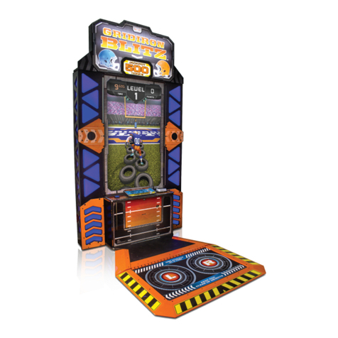
NAMCO PAC-MAN SMASH Installation manual

M259_Intro_EN.indd 2 2/5/2013 7:39:59 AM
PAC-MAN SMASH
Operation Manual
To ensure safe operation of the machine, be sure to read this Operation Manual before use.
Keep this Operation Manual in a safe place for quick access whenever needed.
The actual product may differ slightly from the illustrations in this Operation Manual.
NAMCO BANDAI Games Inc.

Introduction
Thank you very much for purchasing PAC-MAN SMASH (referred to as “the machine” in this manual).
This Operation Manual describes:
• How to safely install, move, transport, operate, service and dispose of the machine.
• How to make full use of the machine’s functions and operate it correctly.
• How to ensure the safety of players and bystanders.
Contact for this machine and machine repair inquiries
• For inquiries regarding the machine or machine repairs, contact your distributor.
M259_Intro_EN.indd 2 2/5/2013 7:39:59 AM

Test Mode Troubleshooting
1
Levels of Risk / Definition of “Technician”
1. Safety Precautions -Be sure to read to ensure safe operation-
Instructions to the Owner
Ifyou delegatethe workfor installing,moving, transporting,operating, servicingor disposingthe machineto other
people,ensurethatthesepeoplereadtherelevantsectionsofthisoperationmanualcarefullybeforestartingwork,
and observe the corresponding precautions.
1-1 Levels of Risk
The safety and property damage precautions on the machine labels and in this Operation Manual are classified
according to their risk level, as follows.
: Failure to avoid these risks may result in serious injury or death.
: Failure to avoid these risks may result in light injury or damage to other property.
Notes about functionality that are not linked to safety are indicated with the following symbol.
: Information about product functions or protection.
1-2 Definition of “Technician”
ThisOperationManualisdesigned forarcadepersonnel. However,thesections marked“Mustbe performedby a
technician”intheTableofContentsarewrittenfortechnicians.Thesetasksmustbeperformedbytechniciansonly.
Technician:Apersoninvolvedindesign,manufacture,inspectionorserviceatanamusementdevicemanufacturer,
or a person involved routinely in the service or management (such as repair) or amusement devices
and who has specialist knowledge of electricity, electronics or mechanical engineering equivalent to
or higher than a technical high school graduate.
M259_01_EN.indd 1M259_01_EN.indd 1 2/5/2013 7:41:10 AM2/5/2013 7:41:10 AM

1. Safety Precautions -Be sure to read to ensure safe operation-
2
1-3 Critical Safety Precautions
zShould an abnormality occur, turn off the power switch immediately to stop operations. Then, be
suretodisconnectthepowercordplugfromtheoutlet.Operatingthemachinewhiletheabnormality
persists may result in a fire or accident.
zThis machine includes important parts used to ensure the safety of players and bystanders.
Operating the machine while these “important parts for ensuring player and bystander safety” are
broken,damagedor deteriorated,or with defectiveinstallation may resultin an injuryto theplayers
or bystanders. If you discover an abnormality, replace the affected part immediately. To order parts,
contact your distributor.
zDustaccumulatingonthepowercordplugmayresultinafire.Inspecttheplugregularlyandremove
any dust.
zFully insert the power cord plug into the outlet. Poor contact may generate heat and result in a fire
or burns.
zDamagetothepowercordmayresultinafire,electricshockorelectricalleakage.Besuretoobserve
the following.
•Keep the power cord away from heaters.
•Do not twist the power cord.
•Do not forcibly bend the power cord.
•Do not alter the power cord.
•Do not pull the power cord. (Always unplug
byholdingtheplugandnotthepowercord.)
•Do not bundle the power cord.
•Do not place objects on the power cord.
•Do not allow the power cord to be caught
between the machine and other devices or
the wall.
•Do not do anything else that might damage
the power cord.
zDo not expose the power cord and power cord plug to water. It may result in electric shock or
electrical leakage.
zDo not touch the power cord plug with wet hands. It may result in electric shock.
zThe power capacity of the machine is AC 120 V (or 220 V), maximum current consumption 3 A. To
preventfireandelectricshock,useindoorwiringthatconformstothesepowersupplyspecifications.
zUse a power supply voltage range ofAC 110 V to 130 V (or 210 V to 230 V). Using a voltage outside
thisrangemay resultin afire or electricshock. However, toensure thatthe machineoperatesin the
optimum condition, keep the voltage atAC 120 V (or 220 V) as much as possible.
zTo ensure safe use of the machine, be sure to perform the pre-operation inspection (See “7-4 Pre-
operation Inspection” on page 35.) and service (See “8B Service” on page 109.). Omitting these
inspections or service may result in an accident.
zUse the consumables and service parts (including screws) that are specified by NAMCO BANDAI
Games Inc. To order parts, contact your distributor.
zDonotmodifythemachinewithoutpermission.Donotperformanyoperationsthatarenotdescribed
in this Operation Manual. Modifying the machine may create unforeseen hazards.
zIf you decide to transfer ownership of this machine, be sure to provide this Operation Manual with
the machine.
M259_01_EN.indd 2M259_01_EN.indd 2 2/5/2013 7:41:25 AM2/5/2013 7:41:25 AM

1. Safety Precautions -Be sure to read to ensure safe operation-
Test Mode Troubleshooting
3
Critical Safety Precautions / Machine Warning Labels
1-4 Machine Warning Labels
zThe warning labels attached to the machine contain important information for ensuring safety. Be
sure to observe the following.
•To ensure that the warning labels attached to the machine are always clearly visible, install the
machine in an appropriate location with ample illumination and keep the labels clean at all times.
Make sure that the labels are not hidden by other machines or objects.
•Do not remove or alter the warning labels.
•If a warning label becomes excessively dirty or damaged, replace it with a new one. To order
warning labels, contact your distributor.
Warning sticker Goal (red)
Part No.: 461-769
Warning sticker Goal (blue)
Part No.: 461-768
M259_01_EN.indd 3M259_01_EN.indd 3 2/5/2013 7:41:25 AM2/5/2013 7:41:25 AM

1. Safety Precautions -Be sure to read to ensure safe operation-
4
Caution sticker Do NotApproach Net
Part No.: 461-771
Warning sticker Service B (EXP)
Part No.: 461-539
Warning sticker Service B (EXP)
Part No.: 461-539
M259_01_EN.indd 4M259_01_EN.indd 4 2/5/2013 7:41:26 AM2/5/2013 7:41:26 AM

1. Safety Precautions -Be sure to read to ensure safe operation-
Test Mode Troubleshooting
5
Machine Warning Labels
(When transporting the side tower cabinet)
Warning sticker Installation
and Transport
Part No.: 461-770
Warning sticker
Installation and Transport
Part No.: 461-770
M259_01_EN.indd 5M259_01_EN.indd 5 2/5/2013 7:41:26 AM2/5/2013 7:41:26 AM

6
Table of Contents
Introduction
1. Safety Precautions -Be sure to read to ensure safe operation-.........................................................................................1
1-1 Levels of Risk................................................................................................................................................................1
1-2 Definition of “Technician”...............................................................................................................................................1
1-3 Critical Safety Precautions ............................................................................................................................................2
1-4 Machine Warning Labels...............................................................................................................................................3
2. Specifications.........................................................................................................................................................................10
3. Package Contents..................................................................................................................................................................13
4. Overall Structure (Part Names).............................................................................................................................................22
5. Installation..............................................................................................................................................................................24
5-1 Installation Conditions .................................................................................................................................................24
5-1-1 Installation Locations toAvoid........................................................................................................................24
5-1-2 Play Zone for the Installed Machine...............................................................................................................25
5-2 Required Dimensions for the Delivery Route (Such as Doors and Corridors).............................................................26
6. Moving and transporting.......................................................................................................................................................27
6-1 Moving (On the Same Floor).......................................................................................................................................27
6-2 Transporting.................................................................................................................................................................28
6-2-1 Transporting Manually (Such as Carrying on Stairs) .....................................................................................28
6-2-2 Loading and Unloading to and from a Vehicle...............................................................................................30
6-2-3 Transporting on a Vehicle..............................................................................................................................31
7. Operation................................................................................................................................................................................32
7-1 People Who ShouldAvoid Playing..............................................................................................................................33
7-2 Safety Precautions for Playing ....................................................................................................................................33
7-3 Important Parts for Ensuring Player and Bystander Safety.........................................................................................34
7-4 Pre-operation Inspection .............................................................................................................................................35
7-4-1 Safety Inspection Items (Before Power On)...................................................................................................35
7-4-2 Function Inspection Items (After Power On)..................................................................................................36
7-5 Opening and Closing Doors ........................................................................................................................................37
7-5-1 Opening and Closing the Selector Door........................................................................................................37
7-5-2 Opening and Closing the Coin Box Door.......................................................................................................37
7-5-3 Opening and Closing the Goal (L) and (R)Assemblies.................................................................................38
7-6 Explanation of the Power Switch andAdjustment Switches........................................................................................39
7-6-1 Turning the Power Switch On........................................................................................................................39
7-6-2 Adjustment Switches......................................................................................................................................39
7-7 Playing the Game........................................................................................................................................................40
7-7-1 Starting the Game and Game End.................................................................................................................40
7-8 Test Mode....................................................................................................................................................................41
7-8-1 Test Item Selection Mode...............................................................................................................................41
7-8-2 Score LED, Time LED and Circle LED Test...................................................................................................42
7-8-3 Switch Input Test............................................................................................................................................43
7-8-4 Blower Fan ON/OFF Test and Sensor Check................................................................................................45
7-8-5 Solenoid ON/OFF Test and Sensor Check....................................................................................................46
7-8-6 LHopper Motor ON/OFF Test and Sensor Check .........................................................................................47
7-8-7 S Hopper Motor ON/OFF Test and Sensor Check.........................................................................................48
7-8-8 Sound Test.....................................................................................................................................................49
7-8-9 Ticket Dispenser Test.....................................................................................................................................50
7-9 Setting Mode ...............................................................................................................................................................51
7-9-1 Setting Item Selection Mode..........................................................................................................................51
M259_Contents_ENin6.indd 6M259_Contents_ENin6.indd 6 2/5/2013 8:18:00 AM2/5/2013 8:18:00 AM

Table of Contents
7
Test Mode Troubleshooting
7-9-2 Number of coins per game.............................................................................................................................53
7-9-3 Number of plays per game.............................................................................................................................54
7-9-4 Big Bang Mode play time...............................................................................................................................55
7-9-5 Normal Hockey Mode play time.....................................................................................................................56
7-9-6 Mini puck supply frequency more/less setting for Big Bang Mode.................................................................57
7-9-7 3-puck setting for Normal Hockey Mode........................................................................................................58
7-9-8 Attract BGM ON/OFF.....................................................................................................................................59
7-9-9 Mini puck low warning ON/OFF.....................................................................................................................60
7-9-10 Error log.........................................................................................................................................................61
(1) Number of Errors Saved in Error Log Display Mode................................................................................61
(2) Error Log Contents Display Mode............................................................................................................62
7-9-11 Ticket Dispenser Use Setting.........................................................................................................................63
7-9-12 Number of Tickets Paid to Winner.................................................................................................................64
7-9-13 Number of Tickets Paid to Loser....................................................................................................................65
7-9-14 Number of Tickets Paid in case of aTie ........................................................................................................66
7-9-15 Game mode setting........................................................................................................................................67
7-9-16 Return all settings to default settings (factory settings) .................................................................................68
7-10 Mini Puck Low Warning andAdding Mini Pucks..........................................................................................................69
7-10-1 Mini Puck Low Warning..................................................................................................................................69
7-10-2 Adding Mini Pucks .........................................................................................................................................69
7-11 Daily Cleaning .............................................................................................................................................................70
7-11-1 Cleaning the Playing Field.............................................................................................................................70
7-11-2 Cleaning the Goal Covers and Corner Covers ..............................................................................................71
7-11-3 Cleaning the Pucks and Mallets.....................................................................................................................71
7-11-4 Cleaning the Signboard and Cover Panel......................................................................................................72
7-11-5 Cleaning the SlopedAreas ............................................................................................................................73
8. Technician’s Manual - Must be performed by a technician -..............................................................................................74
8A. Installation and Assembly.....................................................................................................................................................74
8A-1 Number of Workers, WorkTime and Work Space.......................................................................................................74
8A-1-1 Number of Workers and WorkTime...............................................................................................................74
(1) Number of Workers..................................................................................................................................74
(2) Work Time................................................................................................................................................74
8A-1-2 Securing Work Space....................................................................................................................................74
8A-2 Assembly.....................................................................................................................................................................75
8A-2-1 Assembling the Table.....................................................................................................................................75
(1)Assembling the Table, Goals and Corner Covers.....................................................................................75
(2) Installing the Nets.....................................................................................................................................86
(3) Installing the Blower Fan..........................................................................................................................89
8A-2-2 LevelAdjusterAdjustment..............................................................................................................................90
8A-2-3 Assembling the Side TowerAssembly...........................................................................................................91
8A-2-4 Installing the LightAssembly..........................................................................................................................94
8A-2-5 Installing the Side TowerAssembly................................................................................................................96
8A-2-6 Preparing the Pucks and Mallets.................................................................................................................105
8A-3 Connecting the Power Cord and Ground ..................................................................................................................106
8A-4 Checks after Installation............................................................................................................................................106
8A-5 Opening and Closing Doors ......................................................................................................................................107
8A-5-1 Opening and Closing the Front Doors.........................................................................................................107
8A-5-2 Opening and Closing the Service Doors Land R........................................................................................107
8A-5-3 Opening and Closing the Rear Panel..........................................................................................................108
M259_Contents_ENin6.indd 7M259_Contents_ENin6.indd 7 2/5/2013 8:18:07 AM2/5/2013 8:18:07 AM

Table of Contents
8
8A-5-4 Opening and Closing the Service Door........................................................................................................108
8B. Service - Must be performed by a technician -..................................................................................................................109
8B-1 Inspection and Service..............................................................................................................................................109
8B-1-1 Inspection Items...........................................................................................................................................109
8B-1-2 Cleaning the Puck Paths..............................................................................................................................110
(1) Cleaning the Insides of the Goal (L) and (R)Assemblies.......................................................................110
(2) Cleaning the Rail (L) and (R)Assemblies...............................................................................................111
(3) Cleaning the Insides of the Land S Buckets (HopperAssembly) ..........................................................112
(4) Cleaning the Hopper Disks and Hopper Bottoms (HopperAssembly)...................................................113
(5) Cleaning the S SliderAssembly .............................................................................................................116
8B-1-3 Removing Jammed Pucks...........................................................................................................................118
(1) Inside the Goal (L) or (R)Assembly .......................................................................................................118
(2) In case of the rail (L)/(R) assembly.........................................................................................................118
(3) Inside the Corner Rail (L) or (R).............................................................................................................119
(4) Inside the Lor S Bucket (HopperAssembly)..........................................................................................120
(5) Inside a Hopper Disk or Hopper Bottom (HopperAssembly).................................................................120
(6) In case of S EscalatorAssembly............................................................................................................121
(7) In case of LEscalatorAssembly.............................................................................................................122
(8) In case of the SliderAssembly ...............................................................................................................123
8B-1-4 Adding Big Pucks.........................................................................................................................................124
8B-2 Error Display (for Technicians)...................................................................................................................................125
8B-2-1 Display when an Error Occurs.....................................................................................................................125
8B-2-2 Resolving Errors..........................................................................................................................................125
8B-3 Troubleshooting.........................................................................................................................................................130
8B-3-1 Overall..........................................................................................................................................................131
8B-3-2 Table top assembly......................................................................................................................................131
8B-3-3 Goal (L) and (R)Assemblies........................................................................................................................132
8B-3-4 Rail (L) and (R)Assemblies.........................................................................................................................132
8B-3-5 CoinAssembly.............................................................................................................................................132
8B-3-6 Hopper assembly.........................................................................................................................................133
8B-3-7 SliderAssembly...........................................................................................................................................134
8B-3-8 S EscalatorAssembly..................................................................................................................................134
8B-3-9 LEscalator assembly...................................................................................................................................134
8B-3-10 Signboard assembly....................................................................................................................................135
8B-3-11 Illuminator assembly....................................................................................................................................135
8B-4 Removing, Installing and ReplacingAssemblies and Parts.......................................................................................136
8B-4-1 Table............................................................................................................................................................136
(1) Removing and Installing the Goal (L) and (R)Assemblies.....................................................................136
(2) Removing and Installing the Rail (L) and (R)Assemblies ......................................................................138
(3) Replacing the Blower Fan......................................................................................................................139
8B-4-2 Goal (L) and (R)Assemblies........................................................................................................................141
(1) Replacing the Goal (L) and (R) Sensors (Photosensor Side) and (Photo-emitter Side) ........................141
8B-4-3 Rail (L) and (R)Assemblies.........................................................................................................................142
(1) Replacing the Rail (L) and (R) Sensors (Upper) and (Middle)................................................................142
(2) Replacing the Rail (L) and (R) Sensors (Lower).....................................................................................144
8B-4-4 Side tower assembly....................................................................................................................................145
(1) Removing and Installing the Side TowerAssembly................................................................................145
(2) Replacing the Main PC Board................................................................................................................146
(3) Replacing the Switching Regulator.........................................................................................................148
(4) Replacing the SSR.................................................................................................................................149
M259_Contents_ENin6.indd 8M259_Contents_ENin6.indd 8 2/5/2013 8:18:07 AM2/5/2013 8:18:07 AM

Table of Contents
9
Test Mode Troubleshooting
8B-4-5 Hopper assembly.........................................................................................................................................150
(1) Replacing the LHopper Motor................................................................................................................150
(2) Replacing the LHopper Motor Sensor...................................................................................................154
(3) Replacing the S Hopper Motor...............................................................................................................155
(4) Replacing the S Hopper Motor Sensor...................................................................................................158
(5) Replacing the S Hopper Motor Driver PC Board....................................................................................159
8B-4-6 SliderAssembly...........................................................................................................................................161
(1) Replacing the Stopper Solenoids (L) and (R).........................................................................................161
(2) Replacing the Stopper (L) and (R) Sensors ...........................................................................................163
8B-4-7 S escalatorAssembly...................................................................................................................................164
(1) Replacing the S divider (L) and (R) Outlet Sensors ...............................................................................164
8B-4-8 Lescalator assembly...................................................................................................................................165
(1) Replacing the Ldivider Solenoid............................................................................................................165
(2) Replacing the Ldivider Sensor...............................................................................................................166
(3) Replacing the Ldivider (L) and (R) Outlet Sensors................................................................................167
8B-4-9 Signboard assembly....................................................................................................................................168
(1) Replacing the Time LED (Time LED PC Board).....................................................................................168
(2) Replacing the Score LED (Score LED PC Board)..................................................................................169
8B-4-10 Illuminator assembly....................................................................................................................................170
(1) Replacing the Circle LED.......................................................................................................................170
8B-4-11 Replacing the LED Fluorescent Light..........................................................................................................173
9. Disposal................................................................................................................................................................................174
10. Parts List...............................................................................................................................................................................176
10-1 Overall.......................................................................................................................................................................176
10-2 Table top assembly....................................................................................................................................................178
10-3 Cabinet (L) assembly.................................................................................................................................................180
10-4 Goal (L) assembly .....................................................................................................................................................182
10-5 Rail (L) assembly.......................................................................................................................................................184
10-6 Cabinet (R) assembly................................................................................................................................................185
10-7 Goal (R) assembly.....................................................................................................................................................187
10-8 Rail (R) assembly......................................................................................................................................................190
10-9 Side tower assembly .................................................................................................................................................191
10-10 Hopper assembly.......................................................................................................................................................194
10-11 Slider assembly.........................................................................................................................................................198
10-12 S escalator assembly ................................................................................................................................................200
10-13 Lescalator assembly.................................................................................................................................................202
10-14 Signboard assembly..................................................................................................................................................204
10-15 Switch plate assembly...............................................................................................................................................204
10-16 Illuminator assembly..................................................................................................................................................205
10-17 LightAssembly ..........................................................................................................................................................206
11. Wiring Diagram.....................................................................................................................................................................207
M259_Contents_ENin6.indd 9M259_Contents_ENin6.indd 9 2/5/2013 8:18:08 AM2/5/2013 8:18:08 AM

10
2. Specifications
(1) Rated power supply AC 120 ±10 V (50/60 Hz),AC 220 ±10 V (50/60 Hz)
(2) Rated power consumption 310 W
(3) Maximum current consumption 3A
(4) Cashbox capacity Approx. 200,000 yen (2,000 100 yen coins)
(5) Dimensions
1) When installed Width (W) 2,030 x Depth (D) 2,570 x Height (H) 2,170 [mm]
2,570 mm 2,030 mm
2,170 mm
2) When disassembled
Table Width (W) 1,690 x Depth (D) 2,570 x Height (H) 1,350 [mm]
2,570 mm 1,690 mm
1,350 mm
M259_02_EN.indd 10M259_02_EN.indd 10 2/5/2013 7:43:18 AM2/5/2013 7:43:18 AM

2. Specifications
Test Mode Troubleshooting
11
Specifications
1,530 mm
2,080 mm 120 mm
1,490 mm
840 mm
1,240 mm
1,530 mm1,240 mm
840 mm
Table top assembly Width (W) 1,490 x Depth (D) 2,080 x Height (H) 120 [mm]
Cabinet (L) assembly Width (W) 1,530 x Depth (D) 1,240 x Height (H) 840 [mm]
Cabinet (R) assembly Width (W) 1,530 x Depth (D) 1,240 x Height (H) 840 [mm]
M259_02_EN.indd 11M259_02_EN.indd 11 2/5/2013 7:43:52 AM2/5/2013 7:43:52 AM

2. Specifications
12
Side tower assembly Width (W) 960 x Depth (D) 1,030 x Height (H) 2,050 [mm]
(When the signboard is removed)
Width (W) 960 x Depth (D) 1,030 x Height (H) 1,700 [mm]
880 mm
960 mm 1,030 mm
520 mm
530 mm 2,050 mm
1,700 mm
920 mm
2,050 mm
620 mm
Hopper assembly Width (W) 880 x Depth (D) 520 x Height (H) 530 [mm]
Side tower cabinet Width (W) 920 x Depth (D) 620 x Height (H) 2,050 [mm]
Casters for transport
(6) Weight
1) When installed Approx. 395 kg
2) When disassembled
Table Approx. 280 kg
Side tower assembly Approx. 115 kg
M259_02_EN.indd 12M259_02_EN.indd 12 2/5/2013 7:43:54 AM2/5/2013 7:43:54 AM

Test Mode Troubleshooting
13
Specifications / Package Contents
3. Package Contents
The following items are included when this machine is shipped.
(1) Side tower cabinet Width (W) 920 x Depth (D) 620 x Height (H) 1,710 [mm]
Weight 85 kg
(2) Cabinet (L) assembly Width (W) 1,540 x Depth (D) 1,240 x Height (H) 780 [mm]
Weight 130 kg
(3) Cabinet (R) assembly Width (W) 1,540 x Depth (D) 1,240 x Height (H) 780 [mm]
Weight 115 kg
(4) Table top assembly Width (W) 2,100 x Depth (D) 1,520 x Height (H) 160 [mm]
Weight 100 kg
(5) Hopper assembly Width (W) 950 x Depth (D) 570 x Height (H) 360 [mm]
Weight 30 kg
(6) Center guard Width (W) 1,650 x Depth (D) 700 x Height (H) 70 [mm]
Weight 8 kg
(7) Side net Width (W) 1,240 x Depth (D) 1,130 x Height (H) 160 [mm]
Weight 20 kg
(8) LightAssembly Width (W) 1,370 x Depth (D) 440 x Height (H) 320 [mm]
Weight 16 kg
zMake sure that all the items below are contained in the product package.
zIf any items are missing, contact your distributor.
M259_03_EN.indd 13M259_03_EN.indd 13 2/5/2013 7:45:53 AM2/5/2013 7:45:53 AM

3. Package Contents
14
(1) Side tower cabinet
No. 1 to 3
zPackage contents
No. Name Specification Qty.
1 Operation Manual (this manual) 1
2 Service key 2
3 Torx wrench T25, for M5 1
M259_03_EN.indd 14M259_03_EN.indd 14 2/5/2013 7:46:01 AM2/5/2013 7:46:01 AM

3. Package Contents
Test Mode Troubleshooting
15
Package Contents
(2) Cabinet (L) assembly
8 to 11
3, 4, 6, 7 2
1
5
zPackage contents
No. Name Specification Qty.
1 Service key 2
2 Goal (R) assembly 1
3 Rail (L) assembly 1
4 Rail (R) assembly 1
5 Signboard
1
6 Goal cover (RED) 1
7 Goal cover (BLUE) 1
8 Corner cover Four types: (Red • L),
(Red • R), (Blue • L), (Blue • R) 4 types
9 Mallet
4
10 Big puck 100
11 Mini puck (Pink, orange, green: 100 each) 300
M259_03_EN.indd 15M259_03_EN.indd 15 2/5/2013 7:46:01 AM2/5/2013 7:46:01 AM

3. Package Contents
16
(3) Cabinet (R) assembly
4, 12, 13
16, 17, 18
1, 5, 15
2, 6 to 11, 14
3
zPackage contents
No. Name Specification Qty.
1 Service key 2
2 Screws See “zList of screws” on page 20. 1 set
3 Goal (L) assembly 1
4 Blower fan
1
5 Cash box key 2
6 Side wall 2
7 Side tower bracket (L) 1
8 Side tower bracket (R) 1
9 Center guard bracket (A) 1
M259_03_EN.indd 16M259_03_EN.indd 16 2/5/2013 7:46:02 AM2/5/2013 7:46:02 AM

3. Package Contents
Test Mode Troubleshooting
17
Package Contents
No. Name Specification Qty.
10 Center guard bracket (B) 1
11 Triangle bracket 1
12 Blower bracket (L) 1
13 Blower bracket (R) 1
14 Hopper wall 1
15 Selector door key 2
16 CASHFLOW selector option
cable
1
17 CASHFLOW counter option
cable
1
18 Ticket dispenser option cable 2
(4) Table top assembly
1
zPackage contents
No. Name Specification Qty.
1 Table top assembly 1
M259_03_EN.indd 17M259_03_EN.indd 17 2/5/2013 7:46:03 AM2/5/2013 7:46:03 AM

3. Package Contents
18
(5) Hopper assembly 1
zPackage contents
No. Name Specification Qty.
1 Hopper assembly 1
(6) Center guard
1
zPackage contents
No. Name Specification Qty.
1 Center guard unit
1
M259_03_EN.indd 18M259_03_EN.indd 18 2/5/2013 7:46:04 AM2/5/2013 7:46:04 AM
Table of contents
Other NAMCO Game manuals
Popular Game manuals by other brands

HARVARD
HARVARD G03993 Assembly instructions and rules

Smoby
Smoby BBF Challenger quick start guide

GAELCO
GAELCO Ring Riders Operator's manual

Harvil
Harvil NGD2515 Assembly instructions

Crivit
Crivit 75955 Playing and user instructions

CANADA BILLARD & BOWLING INC
CANADA BILLARD & BOWLING INC BRIDGE installation manual

Radica Games
Radica Games MULTI STRIKE POKER 75058 instruction manual

LEXIBOOK
LEXIBOOK NIMITZ GT2000 instruction manual

Techno Source
Techno Source Sonic The Hedgehog Chaos & Spinball 10615 user manual

Learning Resources
Learning Resources Crazy Creatures EI-2911 manual

Hasbro
Hasbro Beyblade Dranzer F 82631/82500 instructions

Saitek
Saitek Chess Explorer instructions