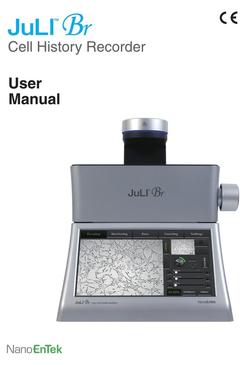
NanoEnTek Juli Installation guide

NanoEnTek Inc. 851-14, Seohae-ro, Paltan-myeon, Hwaseong-si, Gyeonggi-do, 18531, Korea
Tel : +82-2-6220-7940, Fax : +82-2-6220-7999
NanoEnTek Inc. (USA) 240 Bear Hill Road, Suite 101, Waltham, MA 02451, USA / Tel: +1-781-472-2558, Fax: +1-781-790-5649
NESMQ-JST-001E(V.2.0)
Quick manual

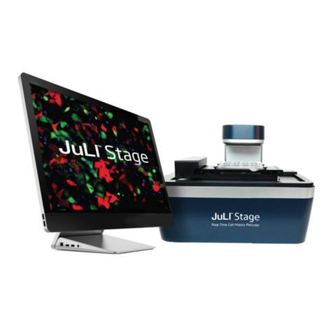
JuLI™Stage, Real-Time Cell History Recorder
2 3
Installation Basic operation
The JuLI™ Stage used in combination with PC (Monitor Resolution 1920x1080) to enables users
to operate the instrument using the computer mouse and keyboard. The JuLI™ Stage basic operations
use the mouse for moving, selecting and zooming in/out.
☞Quick manual describes the mouse function in Default setting (Type 1).
If necessary, you can change the mouse setting type in the Setting menu.
1. Moving: Move the X-Y stage to wells or positions.
• Moving among wells (Inter well)
• Moving within the well (Intra well)
• Moving in view
2. Selection: Select the wells or specic positions which user wants to set.
• Selecting well
• Selecting position
3. Zoom: Zoom in and out of the image in the screen.
• Zoom-in (Scroll up)
• Zoom-out (Scroll down)
• Size bar (Wheel dragging)
[1st Zoom-in] [2nd Zoom-in] [3rd Zoom-in]
1. Open the box and remove the material foam from the box.
2. Carefully lift the instrument out of the box, using the handholds
in the bottom of the base.
3. Place the instrument on a at, level surface (table or incubator).
4. Unscrew the lter change lock module screw.
5. Gently pull lter change lock module screw out, away from the
instrument. Put the lter in the pouch to keep safe.
6. Connect repeater to the PC and two USB cables, then connect to
control box. (PC Monitor Resolution: 1920 ×1080 pixels)
7. Connect the JuLI™ Stage instrument and the Control box and
using the connection cable. Connect the connection cable and control box
matching the blue and red sticker.
☞ Note : Make sure of connection port direction to control box before
connecting.
8. Plug the power cord of PC and instrument into the electrical outlet.
9. Turn the PC and the Control box on by pressing the Power button.
10. Double-click the JuLI™ Stage icon on desktop The JuLI™ Stage
software starts up.
Power port USB port
Filter change lock module
Right mouse
Left mouse
Mouse wheel
☞ Note: Check the connection on the rear side of the PC.

JuLI™Stage, Real-Time Cell History Recorder
4 5
Position Calibration
(Vessel type)
Stitching Image Calibration
(Stitching & Map mode)
1. Press the Move To A01 or B02 button.
Like the picture, stage will move to A01 or B02 well
and the center square displays the current location.
2. Press the Check A01 or B02 button.
If you press the button, The Stage will move to 4 quad-
rants (top, bottom, left and right) to check positioning
around the radius of the well. The outside of well will be
displayed on each square of quad rant. If location adjust-
ment is needed, adjust is the location to be symmetrical
based on the red line. When you double click the loca-
tion, the red line will move to the clicked location.
3. To apply the adjusted value, click Calibration A01 or B02
button.
To check the current applied condition, press Check A01
or B02 button one more time.
4. Press the Move to B02 or C03
(Well number can be changed by vessel type. Basically, it is
expressed in the end well of the relevant vessel type.)
5. Press the Check B02 or C03
Repeat the same process with A01 or B02 well calibration.
6. Press Save button and X button to nish vessel calibration.
1. Select Make Map of Map Mode from Preview tap.
If there is overlapped image during map mode or stitching, use this function.
2. Press Calibration button in the Make Map.
3. Select Horizontal Axis Mode button.
4. Press Calibration distance button to adjust Y-axis
location. Move to appropriate location by dragging
the two overlapped images with the mouse.
5. Press Vertical Axis Mode button.
6. Press Calibration distance button to adjust X-axis
location. Move to appropriate location by dragging
the two overlapped images with the mouse.
7. Press Save button and X button to nish stitching
image calibration.
7. Click X button to end calibration.
JuLI™Stage, Real-Time Cell History Recorder
6 7
Image capture, Save and overlay
1. Select the Preview menu.
2. Press the Vessel button.
3. Select the Vessel type according to your
sample when well type list appears.
5. Move to the well and position required
using the Right button of the mouse. You can
check the vessel image and the moving
state in the navigation window and view eld.
6. Select the LED channel for capturing images.
7. Adjust Exposure, brightness and LED power and
D-Phase, if necessary.
4. Press the Calibration button, if necessary.
Set the Calibration option from rst well to end well.
Image capture, Save and overlay
8. Find optional focus adjusting the Focus
bar and buttons.
9. Press the Capture button to start capturing images.
10. Press the Save button to save the captured images,
if necessary.
11. Once pop-up window appears, assign the storing
path and le type, and press the Save button to
conrm.
12. Select Other LED channels, If necessary to capture
additional images in dierent channels.
Follow Step 6 ~ 10 repeatedly and save images for
each channel.
13. Press the Overlay button. The overlapped images
captured in each channels will be displayed.
14. When overlay button opens the Overlay setting
window, edit parameters according to your
preference.
And then press the Save button to follow steps
10 ~ 11 (The images will be saved as).

JuLI™Stage, Real-Time Cell History Recorder
8 9
9. Press the Default button to equally capture
central position of all wells.
10. The assigned position is marked by green square
on navigation window.
11. Press the Position Add button to complete setting
- the green square is changed to Red.
12. Press the All button when pop-up window appears.
13. Once the wells are nally conrmed, they are
changed to Red color.
15. Turn on the Auto focus toggle button.
There are four additional options of
auto focus function; All Position, All Channel,
Custom AF and All Cycle AF.
14. Enter the detail setting information.
(Please refer to the previous page)
☞Refer to the detail in the manual. (User manual Page. 22~27)
☞Refer to the detail options of Monitoring option
tap in the Option menu (User manual page. 36)
Operation type-1
(for selecting multiple samples and using the Auto focus)
Operation type-1
(for selecting multiple samples and using the Auto focus)
1. Select the Option menu.
2. Press the Vessel button.
3. Select the Vessel type according to your
sample when well type list appears.
4. Check the Selected Vessel type and press
Vessel button again to nish setting.
5. Select the LED channel.
6. Adjust Exposure,Brightness,LED Power and
D-Phase, as neccessary.
7. Select areas you want to capture by dragging with
left mouse button. To select the entire well,
press Select All button.
8. The selected wells are changed to Grey color.

JuLI™Stage, Real-Time Cell History Recorder
10 11
8. Select Other LED channels, If necessary to capture
additional images in dierent channel.
Follow Step 4 ~ 7 repeatedly and save images for
each channel.
9. After adjusting focus and assigning position,
press the Position Add button.
10. Press the OK button when the pop-up window
appears.
11. Once the wells are nally conrmed, they are
changed to Red color.
12. If necessary to set manual focus in other wells,
follow the previous step 1 ~ 11.
13. Enter the detail setting information.
(Please refer to the previous )
☞Refer to the detail options of Monitoring option tap
in the option menu (User manual page. 36)
Operation type-2
(for selecting Individual samples using the Manual focus)
1. Click a well you want to capture using the Right
mouse button.
2. Once the well is selected, stage is automatically moved
to center of well. Use Right mouse button to navigate
around the well to discover points of interest within the
well. The location will be shown by the grid lines.
3. Turn on the Manual Focus toggle button.
4. Select the LED channel.
5. Adjust the Exposure, Brightness and LED power and
D-Phase, if necessary.
6. Find optional focus adjusting the Focus
bar and buttons.
7. Set Focus button is used to assign
optional focus per each position. After setting
the focus of each position, press the Set
Focus button to save setting value.
Operation type-2
(for selecting Individual samples using the Manual focus)

NanoEnTek Inc.
851-14, Seohae-ro, Paltan-myeon, Hwaseong-si, Gyeonggi-do,
18531, Korea
NanoEnTek Inc. (USA)
240 Bear Hill Road, Suite 101, Waltham, MA 02451, USA
Email
Website
Tel : +1-781-472-2558
Fax: +1-781-790-5649
www.julistage.com
www.nanoentek.com
NESMU-JST-001E (V.2.0)
Tel : +82-2-6220-7940
Fax : +82-2-6220-7999
Table of contents
Other NanoEnTek Voice Recorder manuals
Popular Voice Recorder manuals by other brands

Sony
Sony ICD-P17 - Ic Recorder operating instructions

Speech Technology Center
Speech Technology Center Gnome-Nano II Operation manual

Olympus
Olympus DS-3000 Software guide

Olympus
Olympus WS-801 Detailed instructions

Mitsubishi Electric
Mitsubishi Electric DX-NT430E Installation and operation manual

Eurotherm
Eurotherm 5100e user guide