NanoGlobes WLAN-MINDER User manual


WLAN-Minder User Manual
Page 2 of 53 NGCD000423.005 NanoGlobes Ltd
This page left intentional blank

WLAN-Minder User Manual
NanoGlobes Ltd NGCD000423.005 Page 3 of 53
WLAN-Minder
User Manual
(c) COPYRIGHT 2003-2006 NanoGlobes Limited
• No Part of this manual may be reproduced without the
written permission of NanoGlobes Ltd.
• Software licences are granted for use with one processor
and are not transferable.
• NanoGlobes Ltd., make no representations or warranties
with respect to the contents hereof and specifically
disclaims any implied warranties of merchantability or
fitness for any particular purpose.

WLAN-Minder User Manual
Page 4 of 53 NGCD000423.005 NanoGlobes Ltd
WARRANTY
NanoGlobes Ltd warrant the WLAN-Minder RADIUS based control centre unit
against defective materials or workmanship for a period of one year from the date of
original purchase.
This warranty does not apply if the WLAN-Minder unit have been damaged by
neglect, improper handling or by any other cause not arising directly from defective
materials or workmanship.
NOTICE
The information herein has been carefully checked and is believed to be entirely
accurate at time of going to press. However no responsibility is assumed for any
inaccuracies or typographical errors. Furthermore, no liability is assumed arising
from the use of any product detailed within. NanoGlobes Ltd, reserves the right to
make alterations without notice and recognises that the information contained within
does not convey to the purchaser any license under the patent rights of NanoGlobes
Ltd.
All trademarks acknowledged.

WLAN-Minder User Manual
NanoGlobes Ltd NGCD000423.005 Page 5 of 53
Contents
1 Introduction .................................................... 7
1.1 About This Manual. ......................................... 7
1.2 WLAN-MinderFeatures...................................... 8
1.3 WLAN-MinderFrontPanelFeatures ........................... 9
1.4 WLAN-Minder Back Panel Features ............................ 9
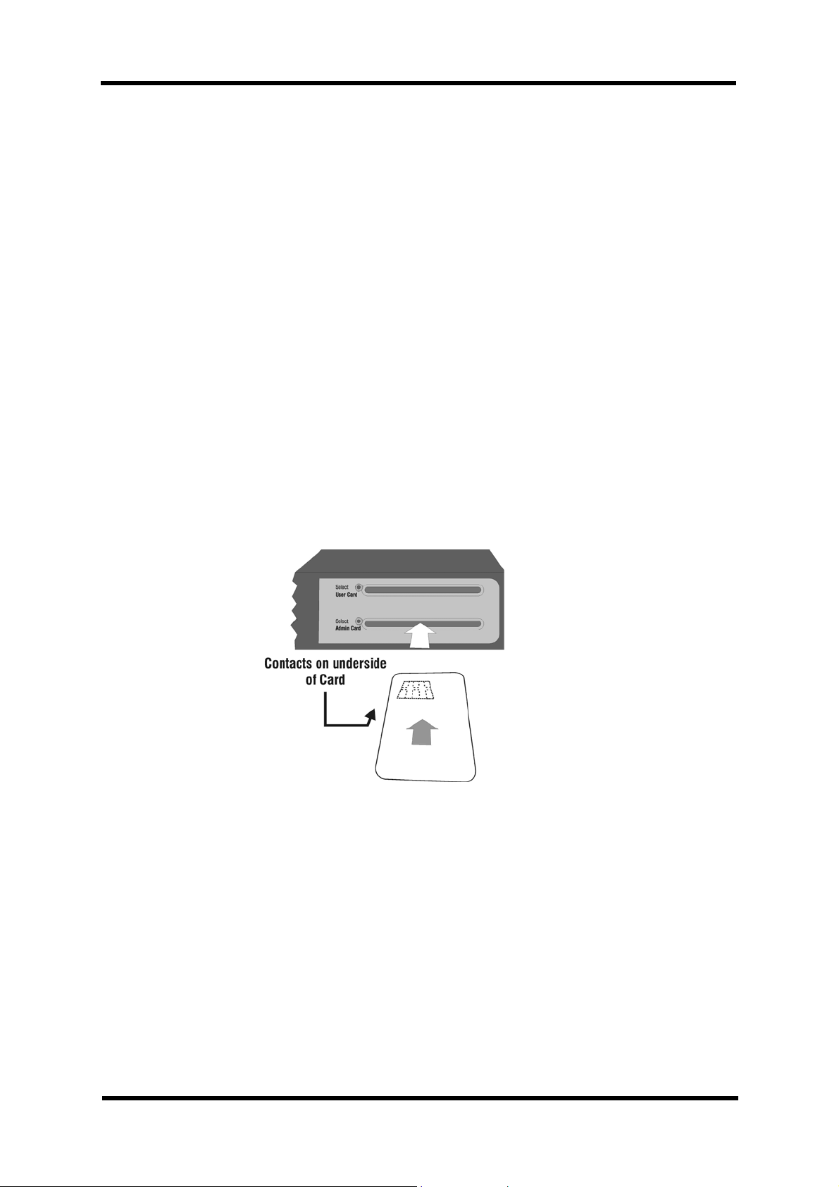
1.5 UsingSmartCardswiththeWLAN-Minder..................... 10
1.6 UsingeTokenswiththeWLAN-Minder ........................ 10
2 InstallingtheWLAN-Minder....................................... 11
2.1 Configuring the IP Address. ................................. 11
2.2 Setting the BIOS Password. ................................. 14
2.3 AttachingTheWLAN-MindertotheNetwork ................... 15
3 InitialisingtheWLAN-Minder-CreatingtheRootCASystem. .......... 17
4 ConfiguringtheWLAN-Minder..................................... 23
4.1 Logging in to the WLAN-Minder web interface. ................. 23
4.2 WLAN-MinderWelcomeMenu ............................... 25
4.3 Configuring the Wireless LAN Access Point. ................... 26
4.4 TokenSettings. ........................................... 28
4.5 Creating User Accounts. ................................... 29
4.6 GeneratingaDuplicateAdministrationCard.................... 31
5 MaintainingtheWLAN-Minder. ................................... 33
5.1 Deleting User Accounts .................................... 33
5.2 Managing Users........................................... 34
5.3 Monitoring theNetwork. ................................... 36
5.4 Monitoring Logins. ........................................ 36
5.5 ViewingaUserToken. ..................................... 37
5.6 Backing Up the WLAN-Minder Configuration Files. .............. 39
5.7 RestoringaWLAN-MinderConfiguration. ..................... 41
5.8 ChangingtheSystemTime/Date............................. 43
6 Appendices.................................................... 44
6.1 HardwareSpecification..................................... 44
6.2 ConnectorPin-out. ........................................ 46
6.3 BIOS Administrator cable [NGL-210] pin-out. ................... 47
6.4 Windows Hyper-Terminal Setup for BIOS Administration. ........ 48
6.5 Unblocking a Blocked Smart Card / eToken. ................... 49
6.6 Two Character Country Codes. .............................. 50
7 References .................................................... 52
7.1 WLAN-Minder WorkstationClientUsersManual. ............... 52

WLAN-Minder User Manual
Page 6 of 53 NGCD000423.005 NanoGlobes Ltd
This page left intentionally blank.

WLAN-Minder User Manual
NanoGlobes Ltd NGCD000423.005 Page 7 of 53
1 Introduction
1.1 About This Manual.
This manual contains information pertinent to the configuration of a Wireless
LAN security system based on 802.1x authentication protocols. The security
system is based on using smart tokens in conjunction with WLAN-Minder client
software [Ref 1], and a central authentication service - provided by the WLAN-
Minder.
The manual covers the installation of the WLAN-Minder, and the issuing of
security tokens such as smart cards and USB eTokens.
The WLAN-Minder solution is designed to operate with Wireless LAN
components that support the IEEE 802.1x Extensible Authentication Protocol.
Nearly all of the newer generation of Wireless LAN products (Client adapters
and Access Points) support this protocol. However certain low cost units and
earlier designs do not support the IEEE 802.1x protocol, these products cannot
be used in a WLAN-Minder solution. In general all components that have been
certified by the Wi-Fi Consortium as being WPA compliant should operate with
the WLAN-Minder.
Only guidance is given in this manual about how the Access Points should be
configured. Each manufacturer will have their own menus and user interfaces
for configuration. Please refer to the Access Point User Manual for obtaining
information on setting up the Access Point unit.

WLAN-Minder User Manual
Page 8 of 53 NGCD000423.005 NanoGlobes Ltd
1.2 WLAN-Minder Features
• Control of Wireless LAN users access to a wired network.
• Plug-and-play solution: no server software installation required.
• Support for IEEE 802.1x compliant EAP-TLS mutual authentication
protocol. Authenticating the client to the network, and the network to the
client.
• Automatic generation of PKI root certificate and user certificates.
• Simple Web based administrator’s interface.
• ISO7816S smart card reader-writer built-in for issuing smart cards
• USB interface built-in to support USB based eTokens.
• RS232 Port for attaching mini serial printer for issuing user PIN numbers.
(Option)
• Smart media socket for providing backup/restore of server configuration
settings.

WLAN-Minder User Manual
NanoGlobes Ltd NGCD000423.005 Page 9 of 53
1.3 WLAN-Minder Front Panel Features
(1) Power On Indicator
(2) Access Point Network: Link and Traffic Status LEDs
(3) Local Network: Link and Traffic Status LEDs.
(4) eToken select LEDs used to indicate a USB eToken should be inserted.
(5) USB sockets for connecting eTokens to be initialised or read.
(6) Dual colour LEDs used to Indicate a smart card should be inserted or is
powered up.
(7) Smart card reader/writer slots.
1.4 WLAN-Minder Back Panel Features
(8) Power Socket +5VDC centre +.
(9) USB device interface for unit configuration from a host PC.
(10) RS232 Serial I/O interface for unit configuration [57600:8:N:1]
(11) Smart Media reader for configuration back up and restore.
(12) Reset button.
(13) Local Area Network Ethernet connector 10/100Mbps.
(14) Access Point Network Ethernet connector 10/100Mbps.

WLAN-Minder User Manual
Page 10 of 53 NGCD000423.005 NanoGlobes Ltd
1.5 Using Smart Cards with the WLAN-Minder
Smart cards are used to store a user’s identity and his network configuration
information. The smart card is used to verify the identity of the owner by
checking the PIN number entered by the owner.
The WLAN-Minder supports two ISO-7816 compliant smart card readers. They
are labelled as [User] and [Admin] respectively. Beside each card slot is a bi-
colour LED, which is used to signal the following states when the web browser
interface is in use:
}A GREEN flashing LED by a card slot is a prompt for the user to enter a
smart card into that slot.
}A RED LED indicates a card is inserted and powered up. The user should
NOT remove the smart card when the RED LED is lit.
INSERTING THE SMART CARD
The contacts surface of the smart card should be face down, and the card
inserted with the contacts at the edge closest to the centre of the WLAN-Minder
unit.
1.6 Using eTokens with the WLAN-Minder
USB eTokens may be used as an alternative to a smart card for storing a user’s
identity and network configuration information.
The WLAN-Minder supports two USB interfaces capable of supporting an
eToken. They are labelled as [User] and [Admin] respectively. Beside each USB
socket is an GREEN LED.
}A GREEN flashing LED by a USB socket is a prompt for the user to enter
an eToken. The Flashing will stop when the eToken is inserted.
ENSURE the CORRECT ORIENTATION is used when INSERTING the
eToken.

WLAN-Minder User Manual
NanoGlobes Ltd NGCD000423.005 Page 11 of 53
2 Installing the WLAN-Minder.
}The WLAN-Minder must first be given a valid IP network address before it
can be placed on the network. This is achieved by using the BIOS menu
as outlined in this section. Once the IP address has been configured all
further configuration is performed using a web browser interface.
}The BIOS menu must be used to set the IP address. This menu can only
be entered from the SERIAL RS232 port on the read panel of the WLAN-
Minder.
2.1 Configuring the IP Address.
}Connect the WLAN-Minder Administrator RS232 port to a serial COM port
on a PC using the provided NGL-210 cable (9-D Female to 9-D Female).
}Connect one end of the supplied RS232 Cable to the connector labelled
[Administration RS232] on the rear panel of the WLAN-Minder.
}Connect the other end of the cable either to a Serial Terminal or to the
COM1 (or COM2) port of a PC running a terminal emulation program [See
Appendix 6.4]. The Terminal should be configured for:
[Baud: 57600, Data Bits: 8, Parity: None, Stop Bits: 1, Flow Control:
None]
}Plug in the supplied Power adapter into a Main’s power outlet, then
connect the power jack on the flying lead to the WLAN-Minder power
connector on the rear panel.

WLAN-Minder User Manual
Page 12 of 53 NGCD000423.005 NanoGlobes Ltd
}The RED Power LED will light and the GREEN ADMIN CARD LED will
flash. The following prompt will appear on the terminal.
}NOTE: While logged in to the BIOS menu system the GREEN
ADMIN CARD LED will continue to flash.
}Enter the text: login<Enter>
}NOTE: The login command will only be accepted while the
GREEN smart card LED is flashing. (Approx. 5 seconds
from RESET/Power ON).
}At the password prompt: password<Enter>
}At the BIOS prompt enter the text: setup<Enter>
}The user will be prompted for the password. (Default is “password”)
}The BIOS will prompt for the IP Address, the IP Subnet Mask and the IP
Gateway address.
}The user should set the IP Address and IP Subnet mask to a suitable
value to be compatible with the network that the WLAN-Minder is to be
attached to.
}The unit then prompts for a TFTP Server path and file name, and the IP
Address of the TFTP server. These parameters may be ignored at this
time. Just use the <Enter> key to skip past these prompts.
-----------------------------------------------------------
BIOS v1.11.1 (c) 2005 NanoGlobes Ltd.
-----------------------------------------------------------
If you want to skip the BIOS command mode, type enter or
wait a few seconds. After this, the system will boot
automatically.
BIOS(0)>
-----------------------------------------------------------
BIOS v1.11.1 (c) 2005 NanoGlobes Ltd.
-----------------------------------------------------------
If you want to skip the BIOS command mode, type enter or
wait a few seconds. After this, the system will boot
automatically.
BIOS(0)>login
Password: ********
BIOS(1)>

WLAN-Minder User Manual
NanoGlobes Ltd NGCD000423.005 Page 13 of 53
}The settings are then automatically written to flash memory within the
WLAN-Minder.
}The user may view the settings to confirm the unit is configured correctly
by using the “ view” command.
}Once the IP settings have been set, it is STRONGLY RECOMMENDED
that the user change the BIOS Password to prevent unauthorised
changes to the IP settings. Of the WLAN-Minder.
}For the changes to take effect and to restart the unit, either cycle the
power to the unit (Power Off / On) or depress and release the RESET
switch which is accessible on the rear panel of the WLAN-Minder unit.
BIOS(1)>setup
Enter password : ********
LAN IP [192.168.1.100] ? 192.168.1.66
LAN MASK [255.255.255.0] ? 255.255.255.0
LAN GATEWAY [192.168.1.1] ? 192.168.1.200
TFTP Server IP [192.168.1.33] ?
TFTP Home Directory [/home/tftp] ?
Write System Configuration Parameters to Flash ...Done!
BIOS(2)>
BIOS(2)> view
Read System Configuration Parameters from flash ...Done!
+==================================================+
| System Configuration Table |
+==================================================+
| System Parameters |
| Vendor Name : NanoGlobes Ltd. |
| Host Name : NGLMinder_802328 |
+--------------------------------------------------+
| Upgrade Parameters |
| TFTP home : /home/tftp |
| TFTP Server : 192.168.1.33 |
+--------------------------------------------------+
| LAN Configuration Parameters |
| LAN MAC : 00:c0:bf:80:23:28 |
| WAN/AP MAC : 00:c0:bf:90:23:28 |
| LAN IP : 192.168.1.66 |
| LAN SUBNET : 255.255.255.0 |
| LAN Gateway : 192.168.1.200 |
+==================================================+
BIOS(3)>

WLAN-Minder User Manual
Page 14 of 53 NGCD000423.005 NanoGlobes Ltd
2.2 Setting the BIOS Password.
}The user should change the default BIOS password to protect the
configuration of the WLAN-Minder.
}To change the BIOS password the user must enter the BIOS menu in the
manner described in 2.1
}At the prompt enter the password command: passwd
}The user is prompted to enter the existing password. (The manufacturing
default password is “password”).
}Then the user is prompted to enter his new password twice. Note the
password letters are not echoed directly, only a “*” character is displayed
for each character typed.
}If the two password entries do not match each other a message “Input
Error - Password not changed.” is displayed. The user must run the
passwd command again.
-----------------------------------------------------------
BIOS v1.11.1 (c) 2005 NanoGlobes Ltd.
-----------------------------------------------------------
If you want to skip the BIOS command mode, type enter or
wait a few seconds. After this, the system will boot
automatically.
BIOS(0)> login
Password: ********
BIOS(1)> passwd
First enter the current password ...
Password: ********
New password (max 15 characters): ********
Confirm new password : ********
BIOS(2)>

WLAN-Minder User Manual
NanoGlobes Ltd NGCD000423.005 Page 15 of 53
2.3 Attaching The WLAN-Minder to the Network
}The WLAN-Minder should only be attached to the user’s LAN once the IP
address has been configured as outlined in section 2.1,
}The WLAN-Minder should be connected by a CAT-5 Ethernet cable
directly to a 10/100MB Ethernet Hub or Switch.
}The connection must be made using the connector labelled [Network
LAN] on the rear panel of the WLAN-Minder unit.
}Check the LAN Link light on the front panel of the WLAN-Minder lights up
(GREEN).
}The user may confirm that the Ethernet link is working by issuing a PING
command to the WLAN-Minder from another computer on the same
subnet network.
Microsoft Windows 2000 [Version 5.00.2195]
(C) Copyright 1985-2000 Microsoft Corp.
C:\>ping 192.168.1.66 <---- Use IP address set in the WLAN-Minder
Pinging 192.168.1.66 with 32 bytes of data:
Reply from 192.168.1.66: bytes=32 time=10ms TTL=255
Reply from 192.168.1.66: bytes=32 time<10ms TTL=255
Ping statistics for 192.168.1.66:
Packets: Sent = 4, Received = 4, Lost = 0 (0% loss),
Approximate round trip times in milli-seconds:
Minimum = 0ms, Maximum = 10ms, Average = 2ms

WLAN-Minder User Manual
Page 16 of 53 NGCD000423.005 NanoGlobes Ltd
}If the Ping fails to elicit a response from the WLAN-Minder, the user
should check:
}The Ethernet cable is plugged in the LAN Network connector on the
WLAN-Minder.
¤The IP Address of the WLAN-Minder is set correctly.
¤The IP Sub Net Mask of the WLAN-Minder is set correctly.
¤The WLAN-Minder LAN LINK LED is lit GREEN.
¤The WLAN-Minder DATA LED flashes YELLOW when data is
present on the network.
¤The Computer issuing the PING is on the same Subnet as the
WLAN-Minder.
¤The Computer issuing the PING is not behind a firewall.
}When successful communication has been established with the WLAN-
Minder, the remaining configuration can be completed from a web
browser such as Microsoft’s Internet Explorer, or Netscape Navigator etc.
}Simply start the web browser on a computer attached to the same subnet
network as the WLAN-Minder, and in the Location bar of the web browser
enter the IP address of the WLAN-Minder (e.g. http://192.168.1.66). The
WLAN-Minder menu system will then be displayed.

WLAN-Minder User Manual
1Effectively the Root CA Certificate is a master certificate used to identify the
WLAN-Minder and it is used to electronically sign the User certificates
generated by the WLAN-Minder unit.
NanoGlobes Ltd NGCD000423.005 Page 17 of 53
3 Initialising the WLAN-Minder - Creating the Root CA
System.
A new WLAN-Minder must first be initialised with a Root CA certificate system1.
When the unit is first powered on it will automatically enter the correct mode for
the administrator to setup the Root CA system.
}Ensure the WLAN-Minder is attached to the LAN as described in section
2.3
}Start a web browser on a computer attached to the same subnet network
as the WLAN-Minder.
}In the Location bar of the web browser enter the IP address of the WLAN-
Minder.
}After a few seconds, the date and time screen will be displayed.

WLAN-Minder User Manual
Page 18 of 53 NGCD000423.005 NanoGlobes Ltd
}The user must enter the correct date and time. This is an important
operation as the date/time entered is used as a reference in checking the
validity of certificates. See Section 5.8. Each parameters is two numeric
digits.
}With the correct date and time entered click the Set Date and Time
button.
}The System Initialisation menu screen will then be displayed.
}When initialising the system for the first time or for generating a new
certificate system, the administrator should first insert the administrator
smart card and then complete the Admin Details section as follows:

WLAN-Minder User Manual
NanoGlobes Ltd NGCD000423.005 Page 19 of 53
Admin Password: Up to 16 characters. In the range ‘a’..’z’, ‘A’..’Z’, ‘0'..’9',
“%&*+@~?#{}!”. Note the Alpha characters are case
sensitive - so ‘A’ is treaded as different character from ‘a’.
This password is used to provide the security for the backup
and restore facility of the WLAN-Minder.
Admin Password. (Confirm) Enter the Password a second time, in order to check
the correct value is stored by the system.
Admin Smart Card PIN The PIN number of the Administrator card. If this is a blank
card direct from the manufacturer the manufacturer will
indicate what the default PIN code is (Typically 0000). If the
card is a used card, then the Administrator must have
access to the PIN code either from their records or the
issuing department.
New Admin PIN If the Administrator wishes to change the current PIN, then
the new PIN to be used should be entered in this field. This
is optional - the Administrators does not have to change the
PIN.
New Admin PIN (Confirm) If the Administrator has chosen to change his PIN,
the new PIN must be entered a second time for
confirmation.
¤With the Admin details entered the administrator should then move to the Root
CA Details section of the display and enter the following information:
Root CA Validity Period The Number of DAYS the newly created certificate
system on the WLAN-Minder is to be valid for. When
this value expires ALL users of the system will have
to have their certificates re-issued.
5 Years ~ 1825 Days
3 years ~ 1095 Days
2 Years ~ 730 Days
1 Year ~ 365 Days
NOTE: Each user certificate will have its own
validity period independent of this setting.
(Except a user validity period cannot exceed
the value set here.)
WARNING: Once a system has been
generated, its validity period cannot be
changed.
Root CA Company Unit: Alpha Numeric Eg: Accounts

WLAN-Minder User Manual
Page 20 of 53 NGCD000423.005 NanoGlobes Ltd
Root CA Company Name: Alpha Numeric Eg: A B C
Industries
Town/City: Alpha Numeric Eg: Newbury
County/State: Alpha Numeric Eg: Berkshire
Country Code: See Section 6.6 Eg: GB
Root CA Common Name: Alpha Numeric Eg: ABCI_Root_CA_S
erver.
NOTE: No space characters should be
present in the Common Name
text.
¤ Once the Administrator has entered the above information and checked
that it is correct, the Generate New System button should be clicked.
¤ The Root CA generation process takes about 60 ~ 90 seconds to
complete. The Administrator is prompted to enter the Administrator’s
smart card if he hasn’t already done so.
¤ When the Rebooting message is displayed the user should click the Back
button.
¤ The system initialisation process is now completed. The Administrator will
now be able to login to the WLAN-Minder settings menu to configure the
unit and create users on the system.
Table of contents
Popular Network Hardware manuals by other brands

Sunell
Sunell Hi3536C Series user manual

HMS Networks
HMS Networks Anybus Wireless Bolt II user manual

Rittal
Rittal CMC III VX Installation and Short User Guide

Idis
Idis DR-6316PS-A quick guide

ZyXEL Communications
ZyXEL Communications NSA-2400 Declaration of conformity

Magma
Magma PCIe Expansion System EB2 user manual