Rittal CMC III VX Product information sheet

Installations- und Kurz-Bedienungsanleitung
Installation and Short User Guide
Notice d'installation et d'utilisation succincte
CMC III Online-Komfortgri VX
CMC III online comfort handle VX
Poignée Confort Online VX CMC III
DK7030.610
DK7030.611

2 Rittal CMC III Online-Komfortgri VX / Online comfort handle VX / Poignée Confort Online VX
Abbildungen / Figures / Figures
1x
1x
M4x12 1x1x M4x16
1x 4x16
M4x25
1x M5x8
1x
1x
1x
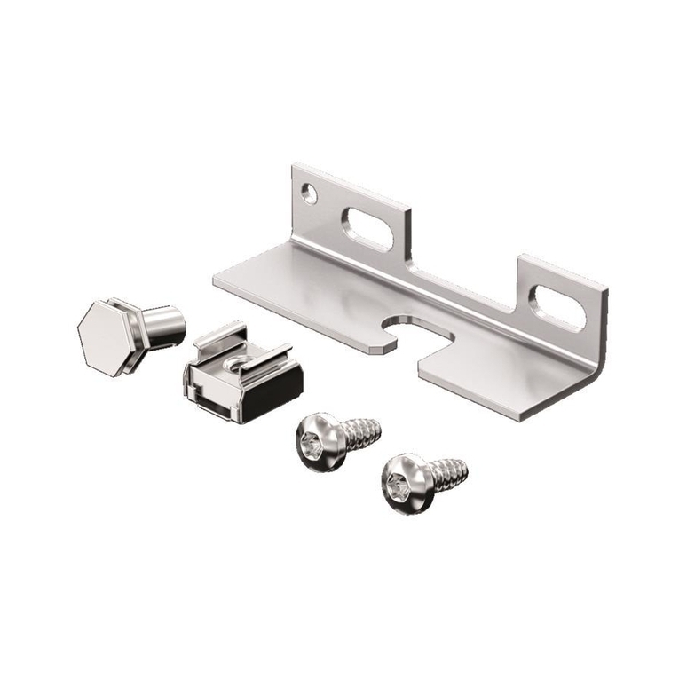
Abb./Fig./Fig.1: Beigelegtes Zubehör / Accessories supplied loose / Accessoires joints à la livraison
42
1
3
Abb./Fig./Fig.2: Bedien- und Anzeigeelemente / Operating and display elements / Organes de commande
et de signalisation
Abb./Fig./Fig.3: Sicherheitshinweise / Safety instructions / Consignes de sécurité

Rittal CMC III Online-Komfortgri VX / Online comfort handle VX / Poignée Confort Online VX 3
Abb./Fig./Fig.4: Montage Stahlblechtür VX und VX IT/ Mounting on the sheet steel door VX and VX IT /
Montage sur la porte en tôle d'acier VX et VX IT
168 mm
36 mm
Ø 4,5
Abbildungen / Figures / Figures
Kabelführung
Cable routing
Guide câble
Rechtsanschlag/Hinge on right/Porte avec charnières à droite
M4x12
Montage/Mounting/Montage
MA= 1,5 ±
0,5 Nm
Bohrbild/Drilling pattern/Gabarit de perçage
123
5 6a 6b4
168 mm
36 mm
Ø 4,5
Linksanschlag/Hinge on left/Porte avec charnières à gauche
Montage/Mounting/MontageBohrbild/Drilling pattern/Gabarit de perçage
123
5 6a 6b4
Kabelführung
Cable routing
Guide câble
M4x12
MA= 1,5 ±
0,5 Nm

4 Rittal CMC III Online-Komfortgri VX / Online comfort handle VX / Poignée Confort Online VX
182,5 mm
17,5 mm
Ø 4,5
Ø 4,5
182,5 mm
17,5 mm
Abb./Fig./Fig.5: Montage Sichttür VX / Mounting on the glazed door VX / Montage sur la porte vitrée VX
Abbildungen / Figures / Figures
Kabelführung
Cable routing
Guide câble
Rechtsanschlag/Hinge on right/Porte avec charnières à droite
M4x16
Montage/Mounting/Montage
MA= 1,5 ±
0,5 Nm
Bohrbild/Drilling pattern/Gabarit de perçage
1 2 3
5 6a 6b4
Linksanschlag/Hinge on left/Porte avec charnières à gauche
Montage/Mounting/MontageBohrbild/Drilling pattern/Gabarit de perçage
1 2 3
5 6a 6b4
Kabelführung
Cable routing
Guide câble
M4x16
MA= 1,5 ±
0,5 Nm

Rittal CMC III Online-Komfortgri VX / Online comfort handle VX / Poignée Confort Online VX 5
Abb./Fig./Fig.6: Montage Sichttür VX IT, belüftete Tür VX IT / Mounting on the glazed door VX IT, vented
door VX IT / Montage sur la porte vitrée VX IT, porte avec aération VX IT
156 mm
20,6 mm
Ø 4,5
156 mm
20,6 mm
Ø 4,5
Abbildungen / Figures / Figures
Kabelführung
Cable routing
Guide câble
Rechtsanschlag/Hinge on right/Porte avec charnières à droite
M4x25
Montage/Mounting/Montage
MA= 1,5 ±
0,5 Nm
Bohrbild/Drilling pattern/Gabarit de perçage
123
5 6a 6b4
Linksanschlag/Hinge on left/Porte avec charnières à gauche
Montage/Mounting/MontageBohrbild/Drilling pattern/Gabarit de perçage
123
5 6a 6b4
Kabelführung
Cable routing
Guide câble
M4x25
MA= 1,5 ±
0,5 Nm
ISO 7380
ISO 7380

6 Rittal CMC III Online-Komfortgri VX / Online comfort handle VX / Poignée Confort Online VX
Abb./Fig./Fig.7: Anschluss des Kabels am Komfortgri und Steckerbelegung / Connecting the cable to
the comfort handle and pin assignment / Raccordement du câble à la poignée Confort et
emplacement des fiches
Abb./Fig./Fig.8: Montage eines Sicherheitseinsatz Nr.3524E / Fitting lock insert no. 3524 E / Montage
d'une serrure N° 3524 E
Abb./Fig./Fig.9: Montage eines Profilhalbzylinders / Fitting a profile half-cylinder / Montage d'une serrure
demi-cylindre
P
in 1
P
in 6
P
in 6
P
in 1
M5x8
4x16
M5x8
4x16
Abbildungen / Figures / Figures

Rittal CMC III Online-Komfortgri VX 7
DE
1 Hinweise zur Dokumentation
Diese Installations- und Kurz-Bedienungsanleitung richtet sich an versiertes Fachpersonal und enthält
nur die wichtigsten Informationen zur Montage, Installation und Funktion des CMC III Online-Komfort-
gri VX (nachfolgend Komfortgri genannt).
1.1 Mitgeltende Unterlagen
Montage-, Installations- und Bedienungsanleitung CMCIII Online-Komfortgri VX.
Sie ist unter www.rittal.de verfügbar und enthält die vollständigen anwendungsrelevanten Informatio-
nen und technischen Daten zum Komfortgri in Hinblick auf:
– Weitere Montagemöglichkeiten
– Funktionen
– Konfigurationsmöglichkeiten
– Detaillierte Bedienungsanweisungen
– Fehlerbehebung
2 Sicherheitshinweise
– Montage und Installation des Komfortgri dürfen nur durch versiertes Fachpersonal erfolgen.
– Das Gehäuse des Komfortgries darf nicht geönet werden.
– Der Komfortgri darf nicht in Kontakt mit Wasser, aggressiven oder entzündbaren Gasen und
Dämpfen kommen.
– Der Komfortgri darf nur innerhalb der spezifizierten Umgebungsbedingungen betrieben werden
(vgl. Abschnitt3.4).
– Siehe auch Abb.3.
3 Produktbeschreibung
3.1 Funktionsbeschreibung
Der Komfortgri übernimmt die Funktion einer Türverriegelung, einer Grihebel-Überwachung und
einer optischen LED Statusanzeige. Für die Master-Key-Funktion ist der Einsatz eines Profilhalbzylin-
ders 40mm nach DIN18252 vorbereitet. Dieser kann als Notönung eingesetzt werden. Wird der
Grihebel geschlossen, verriegelt automatisch die im Komfortgri integrierte Verriegelungs-Mechanik.
Der Gri kann in das CMCIII-System eingebunden werden. Hierzu wird ein CMC III Access Control
(DK7030.202) benötigt, das im Bereich der entsprechenden Tür befestigt wird in Verbindung mit
einem Basissystem. Ein Basissystem kann eine CMC III Processing Unit (DK7030.000), eine CMCIII
Processing Unit Compact (DK7030.010), ein Rittal IoTInterface (SK3124.300) sowie eine Rittal PDU
(DK7979.xxx, außer PDU basic) sein. Die Freigabe des Gries kann in diesem Fall über das Basissys-
tem oder über optionale Zusatzsysteme erfolgen, z.B. ein Zahlencodeschloss (DK7030.222/.223)
oder einen Transponderleser (DK7030.232/.233). Der Komfortgri enthält eine Kennung, durch die er
automatisch vom Basissystem erkannt wird.
Alternativ kann die Önungssteuerung des Komfortgris auch über eine externe Steuerung erfolgen.
In diesem Fall wird sowohl die Versorgungsspannung als auch das Signal zum Önen des Grihebels
von der externen Steuerung über die SPS-Schnittstelle bereitgestellt.
3.2 Bestimmungsgemäße Verwendung
Der CMC III Online-Komfortgri VX dient ausschließlich zur Türverriegelung und der Grihebel-Über-
wachung. Er darf nur zusammen mit einem Basissystem und ggf. dem Access Control (DK 7030.202)
oder alternativ mit einer Ansteuerung über die SPS-Schnittstelle verwendet werden. Eine andere
Verwendung ist nicht bestimmungsgemäß.
Hinweise zur Dokumentation, Sicherheitshinweise, Produktbeschreibung

8 Rittal CMC III Online-Komfortgri VX
DE
3.3 Lieferumfang
– CMC III Online-Komfortgri VX
– Beigelegtes Zubehör (Abb.1)
– Installations- und Kurz-Bedienungsanleitung
3.4 Betriebsbedingungen
Der Komfortgri darf nur unter folgenden Betriebsbedingungen betrieben werden:
Betriebsbedingung CMCIII Online-Komfortgri VX
Temperatur-Einsatzbereich +5°C bis +55°C
Feuchtigkeits-Einsatzbereich 5% bis 70% relative Feuchte, nicht kondensierend
Schutzart IP 40 nach IEC 60 529
4 Montage
4.1 Montageanweisung
Die Montage des Komfortgris erfolgt gemäß Abb.4, Abb.5 bzw. Abb.6.
Hinweis:
Stecker mit den langen Kabeln unten in die Buchse einstecken. Stecker mit den kur-
zen Kabeln oben in die Buchse einstecken (vgl. Abb.7).
5 Installation und Bedienung
5.1 Bedien- und Anzeigeelemente
Die Bedien- und Anzeigeelemente sind in Abb.2 dargestellt.
Legende zu Abb.2
1 Grihebel
2 Taster
3 Master-Key (Profilhalbzylinder)
4 Multi-LED (Ring)
5.2 Installation
Hinweis:
Im Folgenden wird der Anschluss des Komfortgris an ein Basissystem inkl. Access
Control beschrieben. Informationen zum Anschluss über die SPS-Schnittstelle mit
einer externen Steuerung finden Sie in der Hauptanleitung auf www.rittal.de (vgl. Ab-
schnitt1.1).
◾ Trennen Sie zunächst den CAN-Bus am Access Control.
◾ Bringen Sie den Gri an der zu überwachenden Tür an (vgl. Abschnitt4.1 „Montageanweisung“).
◾ Verbinden Sie den Gri ggf. über das Anschlusskabel mit dem Access Control.
◾ Verbinden Sie ggf. ein Lesegerät über das Anschlusskabel mit dem Access Control.
◾ Schließen Sie den CAN-Bus am Access Control wieder an.
Anzeige der Statusänderung:
Produktbeschreibung, Montage, Installation und Bedienung

Rittal CMC III Online-Komfortgri VX 9
DE
– Beim CMC III Access Control blinken während der Initialisierung die beiden grünen sowie die
beiden roten CAN-Bus LEDs am CAN-Bus-Anschluss. Danach leuchten nur noch die grünen
LEDs.
– Die Multi-LED der Processing Unit blinkt dauerhaft in der Reihenfolge grün – orange – rot.
– Die Multi-LED des Access Control blinkt dauerhaft grün, wenn Grihebel und Tür geschlossen
sind. Ansonsten blinkt die Multi-LED rot.
– Die Multi-LED des Komfortgris zeigt blaues Dauerlicht, wenn Grihebel und Tür geschlossen
sind.
– Die Multi-LED des Komfortgris zeigt grünes Dauerlicht bei Freigabe des Grihebels.
– Die Multi-LED des Komfortgris zeigt gelbes Dauerlicht wenn Grihebel und/oder Tür geönet
sind.
◾ Bestätigen Sie je nach verwendetem Basissystem den Anschluss des Komfortgris.
Anzeige der Statusänderung an den CAN-Bus LEDs des Access Control:
– Dauerlicht grüne LEDs: Status CAN-Bus „OK“.
– Dauerlicht rote LEDs: Status CAN-Bus fehlerhaft.
Anzeige der Statusänderung an der Multi-LED der Processing Unit:
– Grünes Dauerlicht: Alle am CAN-Bus angeschlossenen Geräte haben den Status „OK“.
– Oranges Dauerlicht: Mindestens ein am CAN-Bus angeschlossenes Gerät hat den Status
„Warnung“.
– Rotes Dauerlicht: Mindestens ein am CAN-Bus angeschlossenes Gerät hat den Status „Alarm“.
Bei nicht erfolgreicher Installation: vgl. Abschnitt1.1.
5.3 Einstellungen
Standardmäßig ist für den Komfortgri der Mode „Access“ aktiviert. Die Konfiguration des Komfort-
gris erfolgt auf der Registerkarte Monitoring der Weboberfläche des Basissystems.
Weitere Informationen hierzu finden Sie in der Hauptanleitung zum Access Control (DK7030.202) auf
www.rittal.de (vgl. Abschnitt1.1).
Eventuell notwendige Softwareupdates: siehe www.rittal.de oder Anfrage bei Rittal Service (vgl.
Abschnitt6).
6 Service
Zu technischen Fragen wenden Sie sich bitte an:
Tel.: +49(0)2772 505-9052
E-Mail: [email protected]
Homepage: www.rittal.de
Bei Reklamationen oder Servicebedarf wenden Sie sich bitte an:
Tel.: +49(0)2772 505-1855
E-Mail: [email protected]
Installation und Bedienung, Service

10 Rittal CMC III online comfort handle VX
EN
1 Notes on documentation
This installation and short user guide is intended for experienced trained specialists and contains
only the most important information concerning the assembly, installation and function of the CMC III
online comfort handle VX (subsequently called comfort handle).
1.1 Other applicable documents
CMC III online comfort handle VX assembly and operating instructions.
It is available at www.rittal.com and contains the complete application-relevant information and tech-
nical data for the comfort handle with regard to:
– Further assembly possibilities
– Functions
– Configuration possibilities
– Detailed operating instructions
– Troubleshooting
2 Safety instructions
– Assembly and installation of the comfort handle may only be performed by experienced trained
specialists.
– The housing of the handle must not be opened.
– The comfort handle must not come in contact with water, aggressive or inflammable gases and
vapours.
– The comfort handle must only be operated within the specified environmental conditions (see
section3.4).
– See also fig.3.
3 Product description
3.1 Functional description
The comfort handle functions as a door latch, handle lever monitor and visual LED status display. A
40mm semi-cylinder to DIN 18 252 serves as the master key. This can be used to open the handle
in an emergency. If the lever handle is closed, the latch mechanism integrated into the comfort handle
locks automatically.
The handle can be incorporated into the CMCIII system. This requires a CMC III Access Control
(DK7030.202) which is attached near the door in conjunction with a base system. An example of a
base system might be a CMCIII Processing Unit (DK7030.000), a CMCIII Processing Unit Compact
(DK7030.010), a Rittal IoT Interface (SK3124.300) and a Rittal PDU (DK7979.xxx, except PDU
basic). In such cases, the handle can be released via the base system or using additional optional
systems such as a coded lock (DK7030.222/.223) or transponder reader (DK7030.232/.233). The
comfort handle has an identifier enabling it to be detected automatically by the base system.
Alternatively, the opening of the comfort handle can also be controlled via an external controller. In
such cases, the external controller provides both the supply voltage and the signal for opening the
lever handle via the PLC interface.
3.2 Proper use
The CMC III online comfort handle VX is only used for locking the door and monitoring the lever han-
dle. It may only be used in conjunction with a base system and, where applicable, the Access Control
(DK7030.2020) or alternatively with activation via the PLC interface. Any other use is not permitted.
Notes on documentation, Safety instructions, Product description

Rittal CMC III online comfort handle VX 11
EN
3.3 Scope of delivery
– CMC III online comfort handle VX
– Accessories supplied loose (fig.1)
– Installation and Short User Guide
3.4 Operating conditions
The comfort handle may only be operated under the following operating conditions:
Operating conditions CMC III online comfort handle VX
Temperature operational range +5°C to +55°C
Humidity operational range 5% to 70% relative humidity, non-condensing
Degree of protection IP 40 in accordance with IEC 60 529
4 Assembly
4.1 Assembly instructions
The assembly of the comfort handle is carried out as shown in fig.4, fig.5 or fig.6.
Note:
Plug the connector with the long cables into the bottom of the jack. Plug the connec-
tor with the short cables into the top of the jack (see fig.7).
5 Installation and operation
5.1 Operating and display elements
The operating and display elements are shown in fig.2.
Key for fig.2
1 Lever handle
2 Switch
3 Master key (semi-cylinder)
4 Multi-LED (ring)
5.2 Installation
Note:
Below, we describe how to connect the comfort handle to a base system including
Access Control. Information about connecting to an external controller via the PLC
interface can be found in the main operating instructions on www.rittal.com (see sec-
tion1.1).
◾ First disconnect the CAN bus at the Access Control.
◾ Attach the appropriate handle to the door to be monitored (see section4.1 "Assembly instruc-
tions").
◾ Connect this handle with the connection cable to the Access Control.
◾ Connect the reader unit with the connection cable to the Access Control.
◾ Reconnect the CAN bus to the Access Control.
Display of the status change:
Product description, Assembly, Installation and operation

12 Rittal CMC III online comfort handle VX
EN
– With the CMC III Access Control, the two green and two red CAN bus LEDs on the CAN bus
connection will flash during the initialisation process. Once initialisation is complete, only the
green LEDs will be illuminated.
– The multi-LED of the Processing Unit flashes continually in the green – orange – red sequence.
– The multi-LED on the Access Control flashes green continuously when the lever handle and door
are closed. Otherwise, the multi-LED flashes red.
– The multi-LED on the comfort handle displays a steady blue light when the lever handle and
door are closed.
– The multi-LED of the comfort handle shows a steady green light when the handle lever is en-
abled.
– The multi-LED of the comfort handle shows a steady amber light when the handle lever and/or
door are opened.
◾ Depending on the base system being used, confirm that the comfort handle is connected.
Display of the status change on the CAN bus LEDs of the Access Control:
– Green LEDs light continuously: CAN bus status "OK".
– Red LEDs light continuously: CAN bus status faulty.
Display of the status change on the multi-LED of the Processing Unit.
– Continuous green light: All units attached to the CAN bus have the "OK" status.
– Continuous orange light: At least one unit attached to the CAN bus has the "warning" status.
– Continuous red light: At least one unit attached to the CAN bus has the "alarm" status.
If the installation is not successful: see section1.1.
5.3 Settings
"Access" mode is activated as standard for the comfort handle. The comfort handle is configured
under the Monitoring tab of the base system web interface.
More on this topic can be found in the main guide to the Access Control (DK7030.202) at
www.rittal.com (see section1.1).
To determine whether any software updates are required: see www.rittal.com or contact
Rittal Service (see section6).
6 Service
For technical questions, please contact:
Tel.: +49 (0) 2772/505-9052
E-mail: [email protected]
Homepage: www.rittal.com
For complaints or service requests, please contact:
Tel.: +49 (0) 2772/505-1855
E-mail: [email protected]
Installation and operation, Service

Poignée Confort Online VX CMC III Rittal 13
FR
1 Remarques relatives à la documentation
Cette notice d'installation et d'utilisation succincte s'adresse à du personnel qualifié et chevronné et
contient uniquement les informations essentielles pour le montage, l'installation et le fonctionnement
de la Poignée Confort Online VX CMC III (nommé poignée Confort par la suite).
1.1 Autres documents applicables
Notice de montage, d'installation et d'utilisation de la Poignée Confort Online VX CMC III.
Elle est disponible sous www.rittal.com et contient les informations complètes relatives à la mise en
œuvre et les caractéristiques techniques de la poignée Confort dans les domaines suivants :
– Autres possibilités de montage
– Fonctions
– Possibilités de configuration
– Instructions d'utilisation détaillées
– Suppression des défauts
2 Consignes de sécurité
– Le montage et l'installation de la poignée Confort doivent être réalisés uniquement par du person-
nel qualifié et chevronné.
– Le boîtier de la poignée Confort ne doit pas être ouvert.
– La poignée Confort ne doit pas se trouver au contact de l'eau, de gaz et de vapeurs agressifs ou
inflammables.
– La poignée Confort doit être mis en œuvre uniquement dans les conditions ambiantes spécifiées
(voir paragraphe3.4).
– Voir aussi fig.3.
3 Description du produit
3.1 Description fonctionnelle
La poignée Confort assure la fonction de verrouillage de porte, de surveillance du levier de poignée
et d'achage optique de l'état par LED. La fonction passe est assurée par une serrure demi-cylindre
de 40 mm conforme à la norme DIN 18 252. Celle-ci peut être utilisée pour l'ouverture de secours.
Lorsque vous fermez le levier de poignée, un mécanisme intégré verrouille automatiquement la poi-
gnée Confort.
La poignée peut être intégrée dans le système CMCIII. Un contrôle d'accès CMCIII (DK 7030.202),
fixé dans la zone de la porte correspondante, est requis pour cela en association avec un système de
base. Une unité centrale CMCIII (DK 7030.000), une unité centrale compacte CMCIII (DK7030.010),
une interface IoT Rittal (SK3124.300) ainsi qu'une PDU Rittal (DK7979.xxx, hors PDU basic) peuvent
p.ex. constituer un système de base. Le déverrouillage de la poignée peut dans ce cas être réalisé
via le système de base ou via des systèmes complémentaires en option, p.ex. une serrure à code
(DK7030.222/.223) ou un lecteur de transpondeur (DK7030.232/.233). La poignée Confort est dotée
d'un code d'identification qui lui permet d'être automatiquement détectée par le système de base.
La commande d'ouverture de la poignée Confort peut également être réalisée via un système de
contrôle externe. Dans ce cas le système de contrôle externe fournit, via l'interface de l'API, aussi
bien la tension d'alimentation que le signal d'ouverture de la poignée.
3.2 Utilisation conforme au règlement
La poignée Confort Online VX CMC III sert exclusivement au verrouillage de porte et à la surveillance
du levier de poignée. Elle doit être utilisée uniquement avec un système de base et si besoin avec le
contrôle d'accès (DK 7030.202) ou alternativement avec une commande via l'interface de l'API. Toute
autre utilisation est non conforme.
Remarques relatives à la documentation, Consignes de sécurité, Description du produit

14 Poignée Confort Online VX CMC III Rittal
FR
3.3 Composition de la livraison
– Poignée Confort Online VX CMC III
– Accessoires joints à la livraison (fig.1)
– Notice d'installation et d'utilisation succincte
3.4 Conditions de fonctionnement
La poignée Confort doit être mis en œuvre uniquement dans les conditions de fonctionnement
suivantes:
Condition de fonctionnement Poignée Confort Online VX CMC III
Plage de température tolérée +5°C à +55°C
Plage d'humidité tolérée 5% à 70% d'humidité relative, sans condensation
Indice de protection IP 40 selon IEC 60 529
4 Montage
4.1 Instruction de montage
Le montage de la poignée Confort est réalisée conformément à la fig.4, fig.5 ou à la fig.6.
Remarque:
Insérer les fiches avec les câbles longs dans le bas de la prise. Insérer les fiches avec
les câbles courts dans le haut de la prise (voir fig.7).
5 Installation et utilisation
5.1 Organes de commande et de signalisation
Les organes de commande et de signalisation sont présentés sur la fig.2.
Légende pour la fig.2
1 Levier de poignée
2 Bouton
3 Passe (serrure demi-cylindre)
4 LED-multiple (anneau)
5.2 Installation
Remarque:
Le raccordement de la poignée Confort à un système de base avec contrôle d'accès
est décrit par la suite. Des informations pour le raccordement via l'interface de l'API
avec un système de contrôle externe figure dans la notice principale sous www.rittal.de
(cf. paragraphe1.1).
◾ Débrancher d'abord le CAN-Bus du contrôle d'accès.
◾ Poser la poignée correspondante sur la porte à surveiller (voir paragraphe4.1 «Instruction de
montage»).
◾ Connecter cette poignée au contrôle d'accès via le câble de raccordement.
◾ Relier une lecteur au contrôle d'accès via le câble de raccordement.
◾ Rebrancher le CAN-Bus au contrôle d'accès.
Description du produit, Montage, Installation et utilisation

Poignée Confort Online VX CMC III Rittal 15
FR
Achage de la modification d'état:
– Les deux LED CAN-Bus vertes ainsi que les deux rouges de la connexion CAN-Bus sur le
contrôle d'accès CMC III clignotent pendant l'initialisation. Puis seules les LED vertes sont
encore allumées.
– La LED multiple de l'unité centrale clignote de manière continue dans l'ordre vert – orange –
rouge.
– La LED multiple du contrôle d'accès clignote continuellement en vert lorsque le levier de poignée
et la porte sont fermés. Sinon la LED multiple clignote en rouge.
– La LED multiple de la poignée Confort est allumée continuellement en bleu lorsque le levier de
poignée et la porte sont fermés.
– La LED multiple de la poignée Confort est allumée en vert lorsque la poignée est déverrouillée.
– La LED multiple de la poignée Confort est allumée en jaune lorsque la poignée et/ou la porte
sont ouvertes.
◾ Valider le raccordement de la poignée Confort selon le système de base utilisé.
Achage de la modification d'état sur la LED CAN-Bus du contrôle d'accès:
– La LED verte est allumée en continue: état du CAN-Bus «OK».
– La LED rouge est allumée en continue: état défectueux du CAN-Bus.
Achage de la modification d'état sur la LED multiple de l'unité centrale:
– Lumière verte continue: tous les appareils raccordés au CAN-Bus sont dans l'état «OK».
– Lumière orange continue: au moins un appareil raccordé au CAN-Bus est dans l'état «Avertis-
sement».
– Lumière rouge continue: au moins un appareil raccordé au CAN-Bus est dans l'état «Alarme».
En cas d'échec de l'installation: voir paragraphe1.1.
5.3 Réglages
Le mode «Accès» est activé en standard pour la poignée Confort. La configuration de la poignée
Confort est réalisée dans l'onglet Monitoring de l'interface Internet du système de base.
D'autres informations à ce sujet figurent dans la notice principale du contrôle d'accès (DK7030.202)
sous www.rittal.com (voir paragraphe1.1).
Si des mises à jour de logiciel sont éventuellement nécessaires : voir www.rittal.com ou sur demande
au service Rittal (voir le paragraphe6).
6 Service
Pour des questions techniques, veuillez vous adresser à:
Tél. : +49 (0) 2772/505-9052
Site Internet : www.rittal.com
Pour des réclamations ou un service, veuillez vous adresser à:
Tél. : +49 (0) 2772/505-1855
Installation et utilisation, Service

◾ Enclosures
◾ Power Distribution
◾ Climate Control
◾ IT Infrastructure
◾ Software & Services
www.rittal.com/contact
You can find the contact details of all
Rittal companies throughout the world here.
RITTAL GmbH & Co. KG
Auf dem Stuetzelberg · 35745 Herborn · Germany
Phone +49 2772 505-0
10.2021/D-0000-00001953-02
Other manuals for CMC III VX
1
This manual suits for next models
3
Table of contents
Other Rittal Network Hardware manuals
Popular Network Hardware manuals by other brands

Bdcom
Bdcom S5864H Hardware installation manual

Lorex
Lorex L4248 Series quick start guide

Schrack Technik
Schrack Technik HSERG245GS instruction sheet

MikroTik
MikroTik PL7411-2nD Connecting guide

Cambium Networks
Cambium Networks PTP 820C user guide

Texas Instruments
Texas Instruments ThunderLAN TNETE211 Programmer's guide