NANOTEC SMCI33 User manual

Technical Manual
Stepper driver
SMCI33
NANOTEC ELECTRONIC GmbH & Co. KG
Gewerbestraße 11
D-85652 Landsham near Munich, Germany
Tel. +49 (0)89-900 686-0
Fax +49 (0)89-900 686-50

Technical manual
SMCI33 V2.0
Editorial
2 Issue: V 2.0 - 2009-07-01
Editorial/About this manual
©2009
Nanotec®Electronic GmbH & Co. KG
Gewerbestraße 11
D-85652 Landsham / Pliening, Germany
Tel.: +49 (0)89-900 686-0
Fax: +49 (0)89-900 686-50
Internet: www.nanotec.com
All rights reserved!
MS-Windows 2000/XP/Vista are registered trademarks of Microsoft Corporation.
Thank you for choosing a Nanotec stepper driver!
Target group
This technical manual is aimed at designers and developers who need to operate a
Nanotec®stepper motor without much experience in stepper motor technology.
About this manual
This technical manual must be carefully read before installation and commissioning
of the driver.
NanotecNanotec®reserves the right to make technical alterations and further
develop hardware and software in the interests of its customers to improve the
function of this product without prior notice.
This manual has been written with due care. It is exclusively intended as a
technical description of the product and as commissioning instructions. The
warranty is exclusively for repair or replacement of defective equipment, according
to our general terms and conditions, liability for subsequent damage or errors is
excluded. Applicable standards and regulations must be complied with during
installation of the device.
For criticisms, proposals and suggestions for improvement, please contact the
Version/Change overview
Version Date Changes
1.0 2009-02-20 New issue C+P
2.0 2009-07-01 Revision C+P

Technical manual
SMCI33 V2.0
Contents
Issue: V 2.0 - 2009-07-01 3
Contents
1Overview ............................................................................................................................... 4
2Connection and commissioning ........................................................................................ 6
2.1 Connection diagram............................................................................................................... 6
2.2 Commissioning....................................................................................................................... 8
3Connections and circuits.................................................................................................. 10
3.1 Inputs and outputs (I/O): Connector X1 ............................................................................... 10
3.2 Encoder connection: Connector X2 ..................................................................................... 12
3.3 Stepper motor connection: Connector X3............................................................................ 13
3.4 Voltage supply connection: Connector X4........................................................................... 15
3.5 Interface RS485 network: Connector X5 ............................................................................. 16
4Operating modes................................................................................................................ 19
4.1 Overview .............................................................................................................................. 19
5Reference runs and limit switch behaviour .................................................................... 21
5.1 Functional description .......................................................................................................... 21
5.2 Positioning behavior............................................................................................................. 21
6Troubleshooting................................................................................................................. 24
7Technical data.................................................................................................................... 26
Index...................................................................................................................................................... 28

Technical manual
SMCI33 V2.0
Overview
1 Overview
Introduction
The stepper driver SMCI33 is an extremely compact and cost-effective constant
current power output stage with integrated Closed-Loop current control.
Due to the great capacity and functions available, it offers designers and developers a
rapid and simple method of resolving numerous drive requirements with less
programming effort.
It is used for controlling standard stepper motors (including with attached encoders) or
motors with integrated encoders or brakes.
The SMCI33
Variants
The SMCI33 is available in the following variants:
•SMCI33-1: with USB interface (drivers neccessary)
•SMCI33-2: with RS-485 interface
4 Issue: V 2.0 - 2009-07-01

Technical manual
SMCI33 V2.0
Overview
Issue: V 2.0 - 2009-07-01 5
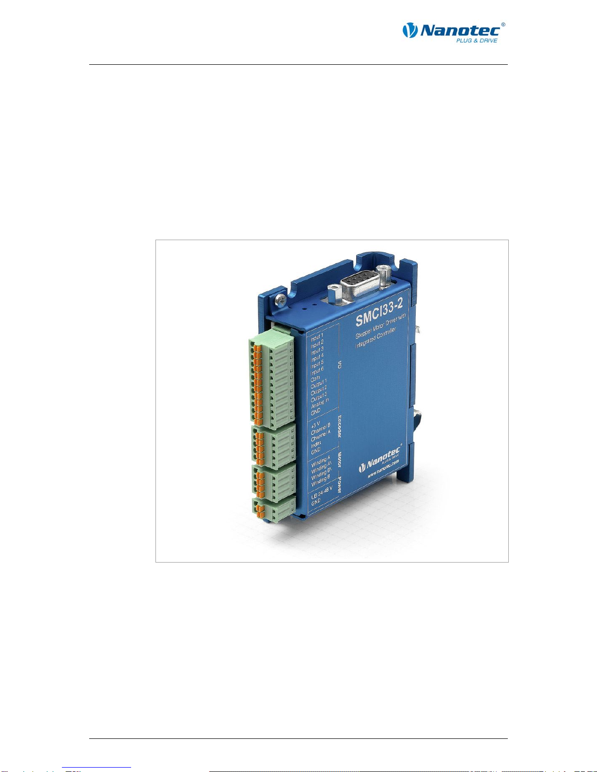
SMCI33 functions
The stepper driver SMCI33 contains the following functions:
•Microstep 1/1 – 1/64 Final output stage (0.014° step resolution)
•Closed-Loop current control (sinusoidal commutation via the encoder)
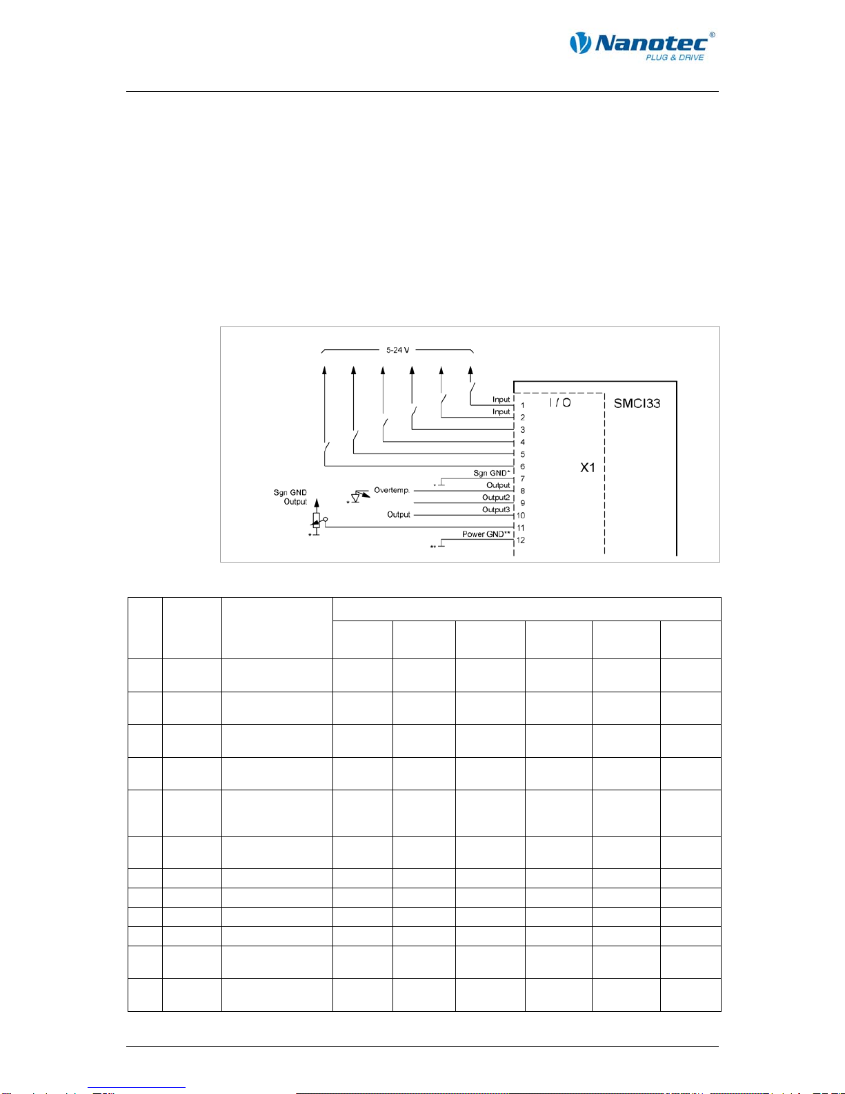
•Powerful DSP microprocessor for flexible I/O
•Rotation monitoring for optional encoder
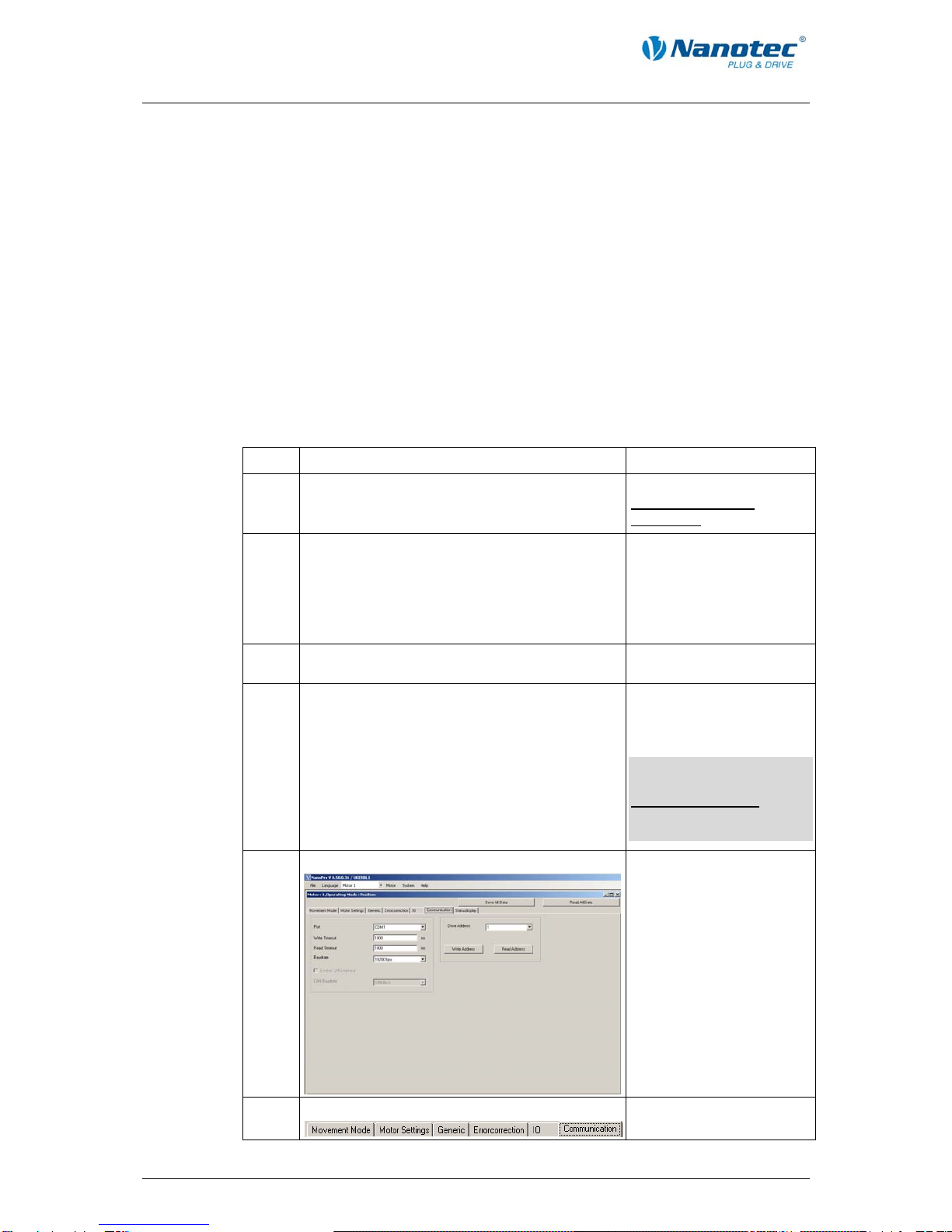
•RS485 or USB interface for parameterisation and control
•Network capability of up to 32 motors
•Easy programming with the Windows software NANOPRO
Operating modes
The following operating modes can be selected:
•Positioning
•Speed
•Flag positioning
•Clock direction
•Analogue or joystick operation (±10 V)
•Analogue positioning mode
•Torque mode
Function overview
The operating behaviour of the motor can be set and optimised according to individual
requirements by setting the motor-related parameters such as phase current
(selectable in 1% increments), step resolution (from 1.8° - 0.014°), as well as the
adaptive microstep (automatic adaption of step width). Machine-related parameters
can be set using the NANOPRO software and significantly reduce commissioning
time:
•Distance in steps, degrees or mm
•Speed in Hertz, rpm or mm/s
•Feed constant in mm/revolution
•Gear reduction with reverse clearance
Three adjustable reference modes (external and internal) enable automatic machine
settings, whereby external reference switches may be inapplicable if there is a shift <
360° possibly due to the index signal of the internal encoder.
Even if stepper motors do not lose steps during normal operation, the integrated
speed control provides additional security in all operating modes, e.g. against motor
stalling or other external sources of error. The monitoring function detects a stalled
motor or step loss after half a step at the most (for 1.8° stepper motors).
Automatic error correction is possible after the drive profile is ended or during the
drive.

Technical manual
SMCI33 V2.0
Connection and commissioning
6 Issue: V 2.0 - 2009-07-01
Closed-Loop current control (sinusoidal commutation via the encoder)
In contrast to conventional stepper motor controls where only the motor is actuated or
the position adjusted via the encoder, sinusoidal commutation controls the stator
magnetic field as in a servomotor via the rotary encoder. The stepper motor acts in
this operating mode as nothing more than a high pole servomotor, i.e. the classic
stepper motor noises and resonances vanish. As the current is controlled, the motor
can no longer lose any steps up to its maximum torque.
If the driver recognises that the rotor is falling behind the stator field due to overload,
adjustments are made with optimal field angle and increased current. In the opposite
case, i.e. if the rotor is running forward due to the torque, the current is automatically
reduced so that current consumption and heat development in the motor and driver
are much lower compared to normal controlled operation.
2 Connection and commissioning
2.1 Connection diagram
Introduction
To operate a stepper motor with the SMCI33 stepper driver, the wiring must be
implemented according to the following connection diagram.
Inputs (Pin 1 to 6) on the connector X1 and the encoder input (connector X2) can be
used optionally.

Technical manual
SMCI33 V2.0
Connection and commissioning
Connection diagram SMCI33
Issue: V 2.0 - 2009-07-01 7

Technical manual
SMCI33 V2.0
Connection and commissioning
2.2 Commissioning
Provisions
The connection and commissioning of the SMCI33 stepper motor are described
below.
The main "First steps" are described here to work as fast as possible with the SMCI33
if you want to work with the NANOPRO software from a PC. You will find more
detailed information in the separate NANOPRO manual.
If you want to work at a later time with a PLC or your own program, you will find the
necessary information in the separate "Command Reference".
Familiarise yourself with the SMCI33 stepper driver and the corresponding control
software NANOPRO before you configure the driver for your application.
Procedure
Proceed as follows to commission the driver:
Step Action Note
1 Install the driver software NANOPRO on your
PC.
See the separate manual on NANOPRO as well.
Download from
www.nanotec.com/
downloads.
2 Connect the driver to the stepper motor
according to the connection diagram.
Connection diagram, see
Section 2.1.
Detailled information on
connections can be found
in Chapter 3 „Connections
and circuits“.
3 Switch on the operating voltage
(24 V DC ... 48 V DC).
The green LED lights up.
4 Connect the driver with your PC.
Use one of the following converter cables for this
purpose:
•ZK-RS485-RS232 for connection to the serial
interface
•ZK-RS485-USB or standard USB cable type
MINI-B for connection to the USB interface
(for SMCI33-1)
Order number:
•ZK-RS485-RS232
•ZK-RS485-USB
Note: Download the
necessary driver from
www.nanotec.com under
the menu item
Accessories/Converter
5 Start the NANOPRO software. The NANOPRO main
menu appears.
6 Select the "Communication" tab.
8 Issue: V 2.0 - 2009-07-01

Technical manual
SMCI33 V2.0
Connection and commissioning
Issue: V 2.0 - 2009-07-01 9
Step Action Note
7 In the field "Port", select the COM port to which
the SMCI33 is connected.
The number of the COM
port to which the driver is
connected can be found in
the device manager of your
Windows' PC (System
Supervision/ System/
Hardware).
8 Select the entry "115200 bps" in the selection
field "Baudrate".
9 Select the "Movement Mode" tab.
10 Click on the button <Test Record> to carry out
the pre-set travel profile.
The connected motor
operates with the pre-set
travel profile (default travel
profile after new
installation).
11 You can now enter your required settings.
For instance, you can enter a new travel profile.
See the separate manual
on NANOPRO as well.

Technical manual
SMCI33 V2.0
Connections and circuits
3 Connections and circuits
3.1 Inputs and outputs (I/O): Connector X1
Introduction
An overview of the assignments can be found in the connection diagram in Section
2.1.. This section looks in detail at the assignment, functions and circuits of the
connector X1..
The connectors and sockets used are from Phönix, Order number: FK-MC 2/4/5/12.
Connection diagram inputs and outputs (I/O) (X1)
Pin assignment connector X1: Inputs and outputs (I/O)
Operating mode
Pin-
No. Name Observations
Position Speed Flag
position Clock
direction Analogue Joystick
1 Input1 5-24 V Optocoupler Start
Reset
Enable Start Enable Enable Enable
2 Input2 5-24 V Optocoupler Travel
profile
Speed Travel
profile
Manual
mode
Speed Speed
3 Input3 5-24 V Optocoupler Travel
profile
Speed Travel
profile
Manual
mode
Speed Speed
4 Input4 5-24 V Optocoupler Travel
profile
Speed Travel
profile
Ext. limit
switch
Speed Speed
5 Input5 5-24 V Optocoupler Travel
profile
Speed Trigger Direction Speed Speed
6 Input6 5-24 V Optocoupler Ext. limit
switch
Direction Ext. limit
switch
Clock Direction
7 Com Signal GND
8 Output1 Open-Collector
9 Output2 Open-Collector
10 Output3 Open-Collector
11 Analogue
In
–10 V ... +10 V Analogue
In
Analogue
In
12 GND Power & Analogue
GND
10 Issue: V 2.0 - 2009-07-01

Technical manual
SMCI33 V2.0
Connections and circuits
Issue: V 2.0 - 2009-07-01 11
Note:
The Com and GND connections are not joined. Com provides the mass for the inputs
and GND provides the mass for the outputs and the internal circuits.
Input circuits
All inputs (apart from the "Analogue In" input) are electrically isolated by optocouplers
from the voltage supply of the SMCI33 and designed for 5 - 24 V input signals at an
input current of 10 mA.
The digital inputs 1 to 6 can be configured with the aid of the software NANOPRO for
“active-high" or “active-low". In addition, these can be freely programmed there, e.g.
as limit switch, enable, etc.
Note:
The voltage should drop below 2 V for safe switching off and be at least 4.5 V for safe
switching on.
Output circuits
The outputs are transistor outputs in Open-Collector circuits (0 switching, max. 30 V /
10 mA). An LED can be integrated to test the output. The LED lights up when the
output is active.

Technical manual
SMCI33 V2.0
Connections and circuits
12 Issue: V 2.0 - 2009-07-01
3.2 Encoder connection: Connector X2
Optional encoder
An optional encoder can be connected to the stepper driver.
By default, the closed-loop control for a three-channel encoder is set up with 500
pulses/revolution in an 1.8° stepping motor. With an 0.9° stepping motor, you should
use an encoder with 1000 pulses/revolution to achieve the same control quality.
Depending on the application, it may make sense to use higher encoder resolutions
(up to max. 2000 pulses/revolution) to improve control quality or to use a lower
resolution (min. 200 pulses/revolution) for Low-Cost applications or for step monitoring
alone.
The following encoder resolutions can normally be processed by the driver: 192, 200,
256, 400, 500, 512, 1000, 1024, 2000, 2048.
Recommended:
Where possible, use Nanotec encoders with the order number
HEDS/HEDL-5540 Xxx.
If an encoder is not used, the mode "Disable" must be set in the tab "Errorcorrection"
in the selection menu "Rotation Direction Mode". See the separate manual on
NANOPRO as well.
Using encoders with line driver
As well as the encoder signal, the encoders of the HEDL series with line driver also
output an inverted signal that contributes to better interference immunity and is
especially recommended for long cable lengths.
SMCI drivers in order to monitor positioning. We recommend shielding and twisting
the encoder line to minimise external interference influences on the encoder signal.
In the third quarter of 2009 Nanotec is bringing an adapter onto the market which can
also evaluate the differential signal.
Encoder connection diagram (X2)
Note:
Complete connection diagram - see Section 2.1.
Pin assignment connector X2: Encoder
Pin-No. Name Observations
1 +5 V
2 Track (A)
3 Track (B)
4 Index track (I)
5 GND

Technical manual
SMCI33 V2.0
Connections and circuits
3.3 Stepper motor connection: Connector X3
General information
The motor is connected to the SMCI33 with a 4-wire cable. Twisted wire pair cables
with braided shields are recommended.
Danger of electrical surges
Mixing up the connections can destroy the output stage!
Never disconnect the link when operating voltage is applied!
Never disconnect lines when live!
Connection diagram stepper motor (X3)
Note:
Complete connection diagram - see Section 2.1.
Pin assignment connector X3: Stepper motor
Pin-No. Name Observations
1 A
2 A/
3 B/
4 B
See also data sheet of connected
stepper motor (colour code of 4
wires).
If you are using a motor with 6 or 8 connections, you need to connect the windings.
The diagram on the next page shows four wiring plans for motors with 6 or 8
connections (page from the Nanotec product catalogue).
Details can be found on the Nanotec website www.nanotec.com.
Issue: V 2.0 - 2009-07-01 13

Technical manual
SMCI33 V2.0
Connections and circuits
14 Issue: V 2.0 - 2009-07-01

Technical manual
SMCI33 V2.0
Connections and circuits
3.4 Voltage supply connection: Connector X4
Permissible operating voltage
The permissible operating voltage for the SMCI33 stepper driver lies between +24 and
+48 V DC; it must not exceed 50 V or fall below 21 V .
A charging condenser with minimum 4700 µF (10000 µF) must be provided for the
operating voltage to prevent exceeding the permissible operating voltage (e.g. during
braking).
Danger of electrical surges
Connect charging condenser with minimum 4700 µF!
Connect a condenser with 10000µF for motors with flange size 86x86 (series
ST8918) or greater!
An operating voltage > 50 V will destroy the output stage!
Mixing up the connections can destroy the output stage!
Never disconnect the link when operating voltage is applied!
Never disconnect lines when live!
Connection diagram voltage supply (X4)
Note:
Complete connection diagram - see Section 2.1.
Voltage supply connections: Connector X4
Pin-No. Name Observations
1 Vcc Switch on the operating voltage
(+24 V DC ... +48 V DC)
2 GND Earth (0 V)
Accessories for voltage supply
Appropriate power packs and charging condensers are available as accessories:
Name Order number
Power pack NTS-xxV-xA
Charging condenser Z-K4700 or Z-K10000
Note:
Further information about accessories can be found on the Nanotec website:
www.nanotec.com
Issue: V 2.0 - 2009-07-01 15

Technical manual
SMCI33 V2.0
Connections and circuits
3.5 Interface RS485 network: Connector X5
SMCI33 in a network
Up to 32 stepper drivers can be controlled in a network from a PC or PLC.
These network connections are set up via the RS485 interface.
RS485 interface (D-Sub socket connector): Connector X5
A 9 pin D-Sub socket connector is located on the top of the SMCI33 (connector X5).
The connector X5 provides the optional connection to the RS485 network.
RS485 socket connector
Pin assignment connector X5: RS485 interface
Pin-No. Name Observations
1 NC not assigned
2 A RS-485 Rx+
3 +5 V Output +5 V
4 Y RS-485 Tx+
5 NC
6 NC
7 B RS-485 Rx–
8 GND Output GND (0 V)
9 Z RS-485 Tx–
16 Issue: V 2.0 - 2009-07-01

Technical manual
SMCI33 V2.0
Connections and circuits
Circuit diagram RS485 network
Issue: V 2.0 - 2009-07-01 17

Technical manual
SMCI33 V2.0
Connections and circuits
18 Issue: V 2.0 - 2009-07-01
Connection requirements
•The RS485 4-wire bus is used as a pure Master-Slave application. All SMCI33 are
connected in parallel as Slaves to the bus.
•Up to 32 stations can be operated on the network.
•The length of the connection lines (stub lines) must be as short as possible and
should not exceed 5 m.
•To avoid reflections during data transmissions, both ends of the bus line should be
fitted with a 120 termination resistor (typical value of the characteristic
impedance of a 24 AWG twisted cable) (R1 to R4).
•To ensure a defined quiescent level, the resistances R5 to R8 must be connected
permanently to the bus according to the above diagram.
•If a converter is connected between the Master and the network, only resistances
R3 and R4 are necessary.
•Note the connection diagram. The output stages can be destroyed if this is not
complied with.
•Use the recommended ZK-RS485-RS232 converter from Nanotec. Reliable
operation cannot be guaranteed with other converters.
Two-wire operation
To enable RS-485 two-wire transmission capability, all bus stations must have a
direction control.
An intelligent converter, which automatically switches to transmission mode when a
start bit is received at the RS-232 interface and returns to reception mode at the end
of the stop bit, enables two-wire operation of the SMCI33. This solution does not
require software support.
We can recommend the ICP-7520 converter, for example, that is available from
Schuricht.
Talk to our Technical Hotline if you require support for this.

Technical manual
SMCI33 V2.0
Operating modes
Issue: V 2.0 - 2009-07-01 19
4 Operating modes
4.1 Overview
Introduction
The stepper driver can be operated in a total of eight different operating modes. Due
to the great capacity and functions available, it offers designers and developers a
rapid and simple method of resolving numerous drive requirements with less
programming effort.
Select the required operating mode for your stepper motor application and configure
the driver according to your requirements. You will find more detailed information in
the separate manual on NANOPRO
Overview of operating modes and their areas of application
Operating mode Application
Positioning mode Use this mode when you wish to travel to a specific
position.
In the positioning mode, the motor travels according to
a specified travel profile from a Position A to a Position
B.
Speed mode Use this mode, when you wish to travel with a specific
speed (e.g. a conveyor belt or pump speed).
In the speed mode, the motor accelerates with a
specified ramp from the starting speed (start frequency
"V Start") to the specified maximum speed (maximum
frequency "V Normal")..
Several inputs enable the speed to be changed on-
the-fly to different speeds
Flag positioning mode The flag positioning mode offers a combination of the
speed and positioning modes. The motor is initially
operated in speed mode; hen a trigger point is
reached, it changes to the positioning mode and the
specified setpoint position (relative to the trigger
position) is approached
This operating mode is used, e.g. for labelling: the
motor first travels with the set ramp to the synchronous
speed of the conveyed goods. When the labels are
detected, the preset distance (position) is travelled to
apply the labels.
Clock direction mode Use this mode, when you wish to operate the driver
with a superordinate controller (e.b. CNC controller)
In the clock direction mode, the SMCI33 is operated
via two inputs with a clock and a direction signal from
a superordinate positioning control (indexer).
Analogue and Joystick mode The motor is controlled in this operating mode simply
with a potentiometer or a joystick (–10 V to +10 V).
Use this mode if you want to use the stepper motor in
simple applications:
•Setting a specific speed e.b. via an external
potentiometer,
•Travelling synchronously with a superordinate
controller with analogue output (–10 V to +10 V).

Technical manual
SMCI33 V2.0
Operating modes
20 Issue: V 2.0 - 2009-07-01
Operating mode Application
Analogue positioning mode Use this mode when you wish to travel to a specific
position.
The voltage level on the analog input is proportional to
the required position, thus enabling servo behavior.
Torque mode Use this mode when you require a specific output
torque independent of the speed as is the case in
typical winding and unwinding applications. The
maximum torque is specified via the analog input.
Selecting the operating mode in NANOPRO
Other manuals for SMCI33
1
Table of contents
Other NANOTEC Controllers manuals