NANOTEC ZK-USB-CAN-1 User manual

Operating Instructions
ZK-USB-CAN-1
Operating Instructions Version: 1.0.0

Contents
1 Introduction.....................................................................................................3
1.1 Version information.....................................................................................................................................3
1.2 Copyright, marking and contact..................................................................................................................3
1.3 Intended use...............................................................................................................................................3
1.4 Warranty and disclaimer.............................................................................................................................3
1.5 Target group and qualification....................................................................................................................4
1.6 EU directives for product safety.................................................................................................................4
1.7 Numerical values........................................................................................................................................ 4
2 Technical details and pin assignment.........................................................5
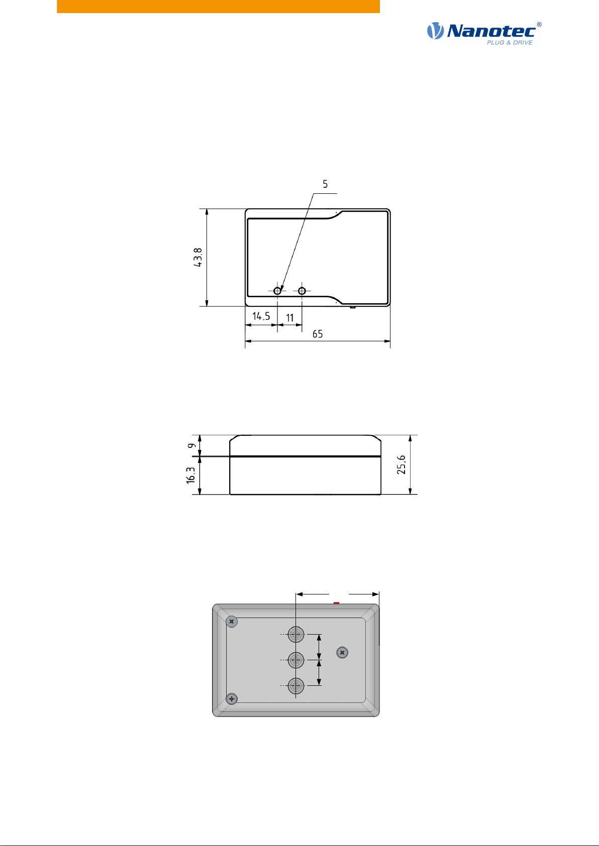
2.1 Dimensioned drawings and installation options..........................................................................................5
2.2 Environmental conditions............................................................................................................................6
2.3 Electrical properties and technical data......................................................................................................6
2.4 LED signaling..............................................................................................................................................6
2.5 Pin assignment........................................................................................................................................... 6
3 Installing driver and adapter.........................................................................9
4 Protocol description.................................................................................... 10
4.1 Configuration and initialization..................................................................................................................10
4.2 Commands for reading and writing..........................................................................................................18
5 Error messages............................................................................................21

1 Introduction
1 Introduction
ZK-USB-CAN-1 is a USB-to-CAN adapter with galvanic isolation between the USB and CAN interface.
It enables CAN networks to be connected. Its compact plastic housing also makes it ideal for mobile
applications.
Power is supplied via the USB 2.0 type-B plug. The CAN interface can be connected to a shielded RJ45
socket or a 4-pin PCB terminal. The adapter supports the USB 2.0 Full-Speed interface and CAN 2.0.
ZK-USB-CAN-1 also has switchable bus termination as well as two status LEDs (USB and CAN).
1.1 Version information
Document
version Date Changes Firmware
version
1.0.0 03/2021 Edition v2110
1.2 Copyright, marking and contact
©2021 Nanotec Electronic GmbH & Co. KG. All rights reserved.
Nanotec Electronic GmbH & Co. KG
Kapellenstraße 6
85622 Feldkirchen
Germany
Phone: +49 89 900 686-0
Fax: +49 (89) 900 686-50
us.nanotec.com
Microsoft®Windows®98/NT/ME/2000/XP/7/10 are registered trademarks of the Microsoft Corporation.
1.3 Intended use
ZK-USB-CAN-1 is used as a component of drive systems in various industrial applications where a computer
needs to be connected to the CAN bus via USB.
Use the product as intended within the limits defined in the technical data (see Electrical properties and
technical data) and the approved Environmental conditions.
Under no circumstances may this Nanotec product be integrated as a safety component in a product or
system. All products containing a component manufactured by Nanotec must, upon delivery to the end user,
be provided with corresponding warning notices and instructions for safe use and safe operation. All warning
notices provided by Nanotec must be passed on directly to the end user.
1.4 Warranty and disclaimer
Nanotec assumes no liability for damages and malfunctions resulting from installation errors, failure to
observe this manual or improper repairs. The selection and use of Nanotec products is the responsibility of
Version: 1.0.0 3

1 Introduction
the plant engineer or end user. Nanotec accepts no responsibility for the integration of the product in the end
system.
Our general terms and conditions at www.nanotec.com apply.
Customers of Nanotec Electronic US Inc. please refer to us.nanotec.com.
NOTE
Changes or modifications to the product are not permitted.
1.5 Target group and qualification
The product and this documentation are directed towards technically trained specialists staff such as:
■Software developers
■Development engineers
■Installers/service personnel
■Application engineers
Only specialists may install and commission the product. Specialist staff are persons who
■have appropriate training and experience in working with fieldbus systems and electrostatically sensitive
components,
■are familiar with and understand the content of this technical manual,
■know the applicable regulations.
1.6 EU directives for product safety
The following EU directives were observed:
■RoHS directive (2011/65/EU, 2015/863/EU)
■EMC directive (2014/30/EU)
1.7 Numerical values
Numerical values are generally specified in decimal (dec) notation. If hexadecimal (hex) notation is used, it is
marked with 0x.
Version: 1.0.0 4

2 Technical details and pin assignment
2.1 Dimensioned drawings and installation options
All dimensions are in millimeters.
You can secure the adapter using one to three M4 screws. Three M4x6 threaded holes are provided for this
purpose:
32.5
10
10
Alternatively, you can also screw on a DIN rail clip and install the adapter in a switch cabinet.
Version: 1.0.0 5

2 Technical details and pin assignment
2.2 Environmental conditions
Environmental condition Value Unit
Ambient temperature (operation) -10 … 70 °C
Ambient temperature (storage) -25 … 85 °C
Relative air humidity (non-condensing) 0 … 95 %
Protection class according to EN/IEC 60529 IP 40
2.3 Electrical properties and technical data
Property Value Unit Note
Power supply 5 V DC via USB
Insulation voltage 1000 / 500 V DC / V AC for 1 minute
CAN baud rate up to 1000 KBaud
2.4 LED signaling
When USB is initialized, the USB status LED lights up green and the device is ready for operation. If
communication is taking place, the LED flashes green. If an error occurs, the LED lights up red.
The CAN status LED has similar functions. When the CAN bus is initialized, the LED lights up green. If
communication is taking place, the LED flashes green. If an error occurs, the LED lights up red.
LED behavior USB/CAN status
continuously red Error
continuously green initialized
flashing green communication taking place
2.5 Pin assignment
Overview
Version: 1.0.0 6

2 Technical details and pin assignment
CAN connection 1 — RJ-45
Type: RJ45 socket
Pin Function Note
1 CAN_H CAN-High
2 CAN_L CAN-Low
3 CAN_GND CAN-Ground
4 - -
5 - -
6 CAN_SHLD connected to housing
7 - -
8 - -
Housing Shield connected with pin 6
CAN connection 2 — PCB terminal
■Type: Phoenix Contact MCV 1.5/ 4-G-3.5
■Mating connector (included in scope of delivery): Phoenix Contact FMC 1.5/ 4-ST-3.5 (or equivalent)
Pin 1 is marked with a 1.
Pin Function Note
1 CAN_GND CAN-Ground
2 CAN_L CAN-Low
3 CAN_SHLD Connection for the shielding, connected to the housing of RJ45
4 CAN_H CAN-High
Termination resistor
Type: Slide switch
This slide switch switches the termination of 120 Ωbetween CAN_H and CAN_L of the CAN bus on or off.
The "left" switch position switches termination on.
Version: 1.0.0 7

2 Technical details and pin assignment
USB connection
Type: USB 2.0, type-B connector. A suitable USB cable is included in scope of delivery.
Version: 1.0.0 8

3 Installing driver and adapter
This chapter explains how to connect the adapter to a PC with Windows 10.
1. Connect the adapter to the PC via USB. The driver is installed automatically and the device bus is
detected as a COM port.
2. To find the number of the assigned COM port:
a. Click the search icon in the task bar.
b. Search for "Device Manager" and select it.
c. Go to "Ports (COM & LPT)".
A USB serial device with the assigned COM number (COM "X") appears.
Version: 1.0.0 9

4 Protocol description
This chapter lists all commands supported by the adapter protocol. You can send the commands via the
COM port (e.g. using a terminal program).
The protocol is based on the specification CiA 309: Access from other networks - Part 3: ASCII mapping.
All commands are confirmed. You may start each command with a sequence number (UNSIGNED32), which
is then included in the response.
Example
// Request: Get name info, sequence=[1234]
[1234] info name
// Response: product name
[1234] name: ZK-USB-CAN-1
The token [net] is allowed to follow the [sequence] due to compatibility reasons, but it is ignored by the
adapter.
4.1 Configuration and initialization
4.1.1 Get Device Information: version, state, ticks, name
You use this command to read out the product information and e.g. carry out initial testing of the connection.
1. Version info
Syntax: "info version"
You use this command to request the version of the CANopen gateway server.
Example
// Request: Get version info
info version
// Response:
620 690 2110.0 352977019 0 00.00 00.00
■620: Vendor ID
■690: Product Code
■2110.0: Firmware Version, Year 2021, Week 10
■352977019: Serial Number
2. State info
Request state of the CAN bus state.
Syntax: "info state"
You use this command to query the state of the CAN bus.
Example
// Request: Get baudrate state info
info state
// Response: -1 if not initialized, >=0 -> baudrate; 0 = 1000kB
state:0
3. Ticks info
Syntax: "info tick"
Version: 1.0.0 10

4 Protocol description
Returns the number of ticks (milliseconds since power on).
Example
// Response: Get tick info
info tick
// Response: tick = 6940278
tick:6940278
4. Name info
Syntax: "info name"
Returns the product name.
Example
// Request: Get name info
info name
// Response: product name
name: ZK-USB-CAN-1
4.1.2 Read Hardware Version
Syntax:0 r 0x1009 0 vs
Example
// Read adapter hardware version: NodeId=0; Index=0x1009;
Subindex=0:
// Data Type= visual string
0 r 0x1009 0 vs
// SDO Read Response: hardware version= W003
"W003"
4.1.3 Read Firmware Version
Syntax:0 r 0x100A 0 vs
Example
// Read adapter firmware version: NodeId=0; Index=0x100A;
Subindex=0:
// Data Type= visual string
0 r 0x100A 0 vs
// SDO Read Response: firmware version= ZKUSBCAN1-FIB-v2110-
B123456
"ZKUSBCAN1-FIB-v2110-B123456"
4.1.4 Read Serial Number
Syntax:0 r 0x4040 0 vs
Version: 1.0.0 11

4 Protocol description
Example
// Read adapter serial number: NodeId=0; Index=0x4040; Subindex=0:
// Data Type= visual string
0 r 0x4040 0 vs
// SDO Read Response: serial number= B123456 21/10-0123
"B123456 21/10-0123"
4.1.5 Initializing gateway
Syntax: "[sequence] init <baudrate>"
Determines the baud rate at which the CAN gateway server operates. The baud rate can be specified as a
value or as a table index of the standard CANopen table.
Index Baud rate
-1 Stop Bus
0 1000
1 800
2 500
3 250
4 125
5 100
6 50
7 20
8 10
NOTE
Autobaud is not supported.
Example
// Request: Initialize CAN-Baudrate 1000 Kbits
init 0
// Response: “OK”
OK
4.1.6 Command set: node ID, network, timeout
You use these commands to set the node ID, network and SDO timeout:
1. Syntax: "[sequence] [net] set node <value>"
Sets the default node ID to be sent with each command, if no other node ID is included in the command.
Example
// Request: Set CAN-NodeId = 127
set node 127
// Response: “OK”
Version: 1.0.0 12

4 Protocol description
OK
2. Syntax: "[sequence] [net] set network <value>"
You set the default network here (used just for compatibility reasons).
Example
// Request: Set CAN-Network = 2
set network 2
// Response: “OK”
OK
3. SDO timeout
Syntax: "[[sequence] [net] node] set sdo_timeout <ms>"
You use this command to set the SDO timeout.
Example
// Request: Set timeout = 1ms
set sdo_timeout 1
// Response: “OK”
OK
4.1.7 Start node (NMT)
Syntax: "[[sequence] [net] node] start"
You use this command to switch the CAN network to the "Operational" state in which PDO transfer takes
place.
Example
// Request: Send Start operational command to NodeId = 1
1 start
// Response: “OK”
OK
// Incoming CAN-Message with CobId = 0x701; Data Length = 1;
// Data = 0x5
:>701 1 5
// Incoming CAN-Message with CobId = 0x281; Data Length = 4;
// Data = 0 0 0 0
:>281 4 0 0 0 0
// Incoming CAN-Message with CobId = 0x381; Data Length = 1;
// Data = 0 0
:>381 2 0 0
// Incoming CAN-Message with CobId = 0x481; Data Length = 4;
// Data = 0 0 0 0
:>481 4 0 0 0 0
Version: 1.0.0 13

4 Protocol description
4.1.8 Stop node (NMT)
Syntax: "[[sequence] [net] node] stop"
You use this command to switch the CAN network to the "Stop" state.
Example
// Request: Send stop command to NodeId = 1
1 stop
// Response: “OK”
OK
// Incoming CAN-Message with CobId = 0x701; Data Length = 1;
// Data = 4
:>701 1 4
4.1.9 Set node Pre-Operational (NMT)
Syntax: "[[sequence] [net] node] preop[erational]"
You use this command to switch the CAN network to the "Pre-Operational" state in which you can change
the PDO mapping.
Example
// Request: Set NodeId = 1 to pre-operational
1 preop
// Response: “OK”
OK
// Incoming CAN-Message with CobId=0x701; Data Length=0x1;
Data=0x7F
:>701 1 7F
4.1.10 Reset node (NMT)
Syntax: "[[sequence] [net] node] reset node"
You use this command to reset the CAN node.
Example
// Request: Send Reset Node to NodeId = 1
1 reset node
// Response: “OK”
OK
// Incoming CAN-Message with CobId=0x701; Data Length=0x1;
Data=0x0
:>701 1 0
Version: 1.0.0 14

4 Protocol description
4.1.11 Reset communication (NMT)
Syntax: "[[sequence] [net] node] reset comm"
Example
// Request: Send Reset communication to NodeId = 1
1 reset comm
// Response: “OK”
OK
4.1.12 Command for message format
Syntax: set msg_format [n]
Where [n] is 0 (default format) or 1:
Format (0)
// All return strings are hex values!
:>601 8 40 63 20 0 0 0 0 0
:>581 8 43 63 20 0 1 0 0 0
Format (1)
// All return strings are hex values!
:>0x00000601 8 0x40 0x63 0x20 0x00 0x00 0x00 0x00 0x00
:>0x00000581 8 0x43 0x63 0x20 0x00 0x01 0x00 0x00 0x00
Example
// Request: Set the format of message to 0
set msg_format 0
// Response: “OK”
OK
4.1.13 Command for CAN mode
Syntax: set can_mode [m]
Where [m] is 0 to 3:
■0 - (Default) normal CAN mode
■1 - Loopback mode
■2 - Silent mode
■3 - Loopback with silent mode
New mode settings become effective after reinitialization of the CAN bus (command init).
Example
// Request: Set CAN mode = 1 (Loopback mode)
set can_mode 1
// Response: “OK”
OK
Version: 1.0.0 15

4 Protocol description
4.1.14 Command for: Filters, Filter ID, Filter Mask
You can use filters to filter the incoming CAN messages.
1. Command for setting Filter
Syntax: set filterX [S]
Where:
■X – 0 to 7: filter number
■S – 0 or 1: 0 = deactivate filter; 1 = activate filter
Example
// Request: Enable filter 0
set filter0 1
// Response: “OK”
OK
2. Command for setting Filter ID
Syntax: set filter idX [id]
Where:
■X – 0 to 7: filter number
■[id] – value for ID comparison
The bits of the filter ID are directly compared with the bits of the ID of the incoming message.
Example
// Request:
set filter_id0 0x581
// Response: “OK”
OK
3. Command for setting Filter Mask
Syntax: filter_maskX [id_mask]
Where:
■X – 0 to 7: filter number
■[id_mask] – bit mask for ID comparison
The bit mask defines which bits of the ID are taken into consideration.
Example
// Request: Set filter MaskId = 0xFFF
set filter_mask0 0xFFF
// Response: “OK”
OK
Example
set filter_id0 0x07D
set filter_mask0 0x0FF
set filter0 1
Only those messages are shown whose least significant bits correspond to the ID 0x7D.
Version: 1.0.0 16

4 Protocol description
After activation of the filter, the following messages would be shown, e.g.:
:>17D 8 0 0 0 0 0 0 0 0
:>47D 4 0 1 1 0
4.1.15 Command Notification
Syntax: set notification [n]
Where [n] is 0 to 3:
■0 - Received RAW CAN messages are not displayed.
■1 (default) - Only received RAW CAN messages that do not relate to the current SDO transfer are
displayed.
■2 - All received RAW CAN messages are displayed.
■3 - All received and sent RAW CAN messages are displayed.
Example
// Request: Set notification = 0
set notification 0
// Response: “OK”
OK
4.1.16 Command for CAN Error list
Syntax: info CAN_ERR
Returns a message in the CAN_ERR format: [REC] [TEC] [LEC] [BOFF] [EPVF] [EWGF]
Where:
■[REC] - Error counter (receive error)
■[TEC] - Least significant byte of the error counter (transmit error)
■[LEC] - Last error code:
□0: No error
□1: Stuff Error
□2: Form Error
□3: Acknowledgment Error
□4: Bit recessive Error
□5: Bit dominant Error
□6: CRC Error
□7: Reserved
■[BOFF] - CAN bus OFF flag (0 or 1)
■[EPVF] - CAN bus error passive flag (0 or 1)
■[EWGF] - CAN bus error warning flag (0 or 1)
Example
// Request: Get info for a CAN error
info CAN_ERR
//Response CAN_ERR: [REC] [TEC] [LEC] [BOFF] [EPVF] [EWGF]
CAN_ERR: 0 0 0 0 0 0
Version: 1.0.0 17

4 Protocol description
4.2 Commands for reading and writing
The following table shows all supported data types and the format used in the commands.
Data Type Format
SIGNED8 i8
SIGNED16 i16
SIGNED32 i32
UNSIGNED8 u8
UNSIGNED16 u16
UNSIGNED32 u32
Octet String (base64 encoded data) os
Domain (base64 encoded data) d
Visual String (see following section) vs
Visual Strings
You can use visual strings inside quotes:
"vs"
Escape sequences are also supported inside:
Escape Sequence Format
Backslash \\ - character \
Single Quotation Mark \' - character '
Double Quotation Mark \" - character "
Question Mark \? - character ?
You can also use one of the following special control characters:
Control Character Format
Bell \a
Backspace \b
Form Feed \f
Line Feed \n
Carriage Return \r
Horizontal Tab \t
Vertical Tab \v
Octal Number of ASCII Character \xNNN, where NNN the octal number of the ASCII
character you want to place inside the escape
sequence
4.2.1 Command "r" (SDO Read Request)
Syntax:[[sequence] [net] node] r <multiplexer> <datatype>
Version: 1.0.0 18

4 Protocol description
Example
// SDO Read Request: NodeId=1; Index=0x1000; Subindex=0:
// Data Type=UInt32
1 r 0x1000 0 u32
// SDO Read Response: Value = 393618 = 0x00060192
393618
4.2.2 Command "w" (SDO Write Request)
Syntax: [[sequence] [net] node] w <index> <subindex> <datatype> <value>
Example
// SDO Write Request: NodeId=1; Index=0x1016; Subindex=0:
// Data Type=UInt32, Value = 100
1 w 0x60FE 1 u32 100
// Response: “OK”
OK
4.2.3 Command "wl" (Initiate download SDO command for large data)
Syntax: "[sequence] [net] [node] wl <multiplexer> <command-specifier> <datatype>
<overall_size> <value>"
This command is used for writing large quantities of data and is directly linked to the "wlseg" command (for
further details, see CiA 309:Access from other networks - Part 3: ASCII mapping).
4.2.4 Command "rl" (Initiate upload SDO command for large data)
Syntax: "[sequence] [net] [node] rl <multiplexer>"
This command is used for reading large quantities of data and is directly linked to the "NEXT" command (for
further details, see CiA 309:Access from other networks - Part 3: ASCII mapping).
4.2.5 Command "wlb" (Initiate download SDO command for large data)
Syntax: "[sequence] [net] [node] wlb <multiplexer> <command-specifier> <datatype>
<overall_size> <value>"
This command functions in the same way as "wl", but with SDO block transfer.
4.2.6 Command "rlb" (Initiate upload SDO command for large data)
Syntax: "[sequence] [net] [node] rlb <multiplexer>"
This command functions in the same way as "rl", but with SDO block transfer.
4.2.7 Command for SDO abort
Syntax: [sequence] [net] sdo_abort [force]
Aborts the SDO tranfer with the commands "wl(b)" and "rl(b)" with the SDO abort code 0x05000000. With
[force], an SDO abort request is sent, even if there is no ongoing SDO transfer.
Version: 1.0.0 19

4 Protocol description
Example
// Request: SDO abort
sdo_abort
// Response: “OK”
OK
4.2.8 Command "rm" (remote request)
Syntax: [sequence] [net] rm <cobid>
Example
// Request: Send remote request
rm 0x181
// Response: “OK”
OK
4.2.9 Command "wm" (write CAN message)
Syntax: [sequence] [net] wm <cobid> <dataLength> <value1>[..<value8>]
Example
// Request: CobId=0x00;
wm 0 2 2 0
// Response: “OK”
OK
// Incoming CAN-Message with CobId=0x701; Data Length=1; Data=0x4
:>701 1 4
4.2.10 Command ":<" (send CAN message)
Syntax: [sequence] [net] :< <cobid> <dataLength> <value1>[..<value8>]
All values are in hexadecimal notation, without the prefix 0x.
Example
// Request: CobId=0x1F4;
:< 1F4 5 21 5A 3 1 CA
// Response: “OK”
OK
Version: 1.0.0 20
Table of contents