manuals.online logo
Brands
  1. Home
  2. •
  3. Brands
  4. •
  5. Napofix
  6. •
  7. TV Mount
  8. •
  9. Napofix VWPO2600 User manual

Napofix VWPO2600 User manual

VWPO2600 70kg
(154lbs)
200 x 200 / 300 x 200
300 x 300 / 400 x 200
400 x 300 / 400 x 400
600 x 400
45’’ - 70’’
INSTALLATION MANUAL / INSTRUÇÕES DE MONTAGEM
Suporte de Parede Video Wall 600mm Micro Ajustável
Wall Mount Video Wall 600mm Micro Adjustable
1. Fixe o sistema Pop-out com a peça plástica/ Lock the Pop-out module with the plastic locking pieces
Manutenção:
• Por favor verique que o equipamento se mantêm seguro para utilização em intervalor regulares
(pelo menos uma ver a cada três meses).
• Contacte o seu distribuidor sempre que tiver alguma dúvida.
Maintenance:
• Check that the bracket is secure and safe to use at regular intervals (at least every three months).
• Please contact your distributor if you have any questions.
1
2
• Do not begin the installation until you have read and understood all the instructions and warnings
contained in this installation sheet. If you have questions regarding any of the instructions or
warnings, please contact your local distributor.
• This mounting bracket was designed to be installed and utilized ONLY as specified in this manual.
Improper installation of this product may cause damage or serious injury.
• This product should only be installed by someone with good mechanical ability who has basic
building experience and fully understands this manual.
• Make sure that the supporting surface will safely support the combined weight of the equipment
and all attached hardware and components.
• Always use an assistant or mechanical lifting equipment to safely lift and position the equipment.
• Tighten screws firmly but do not overtighten. Over tightening can cause damage to the items.
This greatly reduces their holding power.
• This product is intended for indoor use only. Using this product outdoors could lead to product
failure and personal injury.
• Não comece a instalação antes de ler e compreender todas as instruções e avisos
contidos nesta folha de instalação. Se tiver dúvidas sobre qualquer uma das instruções ou
avisos, entre em contato com seu distribuidor local.
• Este equipamento foi projetado para ser instalado e utilizado SOMENTE conforme
especificado neste manual. A instalação inadequada deste produto pode causar danos
ou lesões graves.
• Este produto só deve ser instalado por alguém com boas competências mecânica que
compreenda totalmente este manual.
• Certifique-se de que a superfície de suporte irá suportar com segurança o peso
combinado do equipamento e todo o hardware e componentes anexados.
• Recorra sempre de assistente ou equipamento de elevação mecânica para levantar e
posicionar o equipamento com segurança.
• Aperte os parafusos firmemente, mas não aperte demais. O aperto excessivo pode
causar danos aos itens. Isso reduzirá muito seu poder de retenção
• Este produto destina-se apenas a uso interno. Usar este produto ao ar livre pode levar
a falhas e danos pessoais.
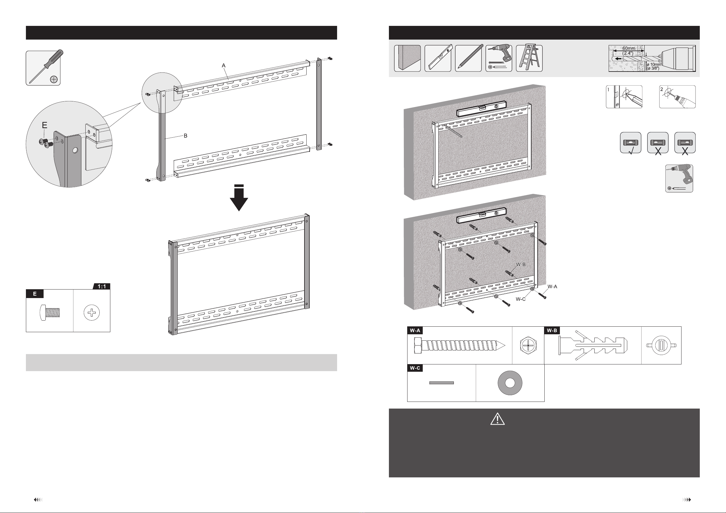
Material necessário / Required for Installation
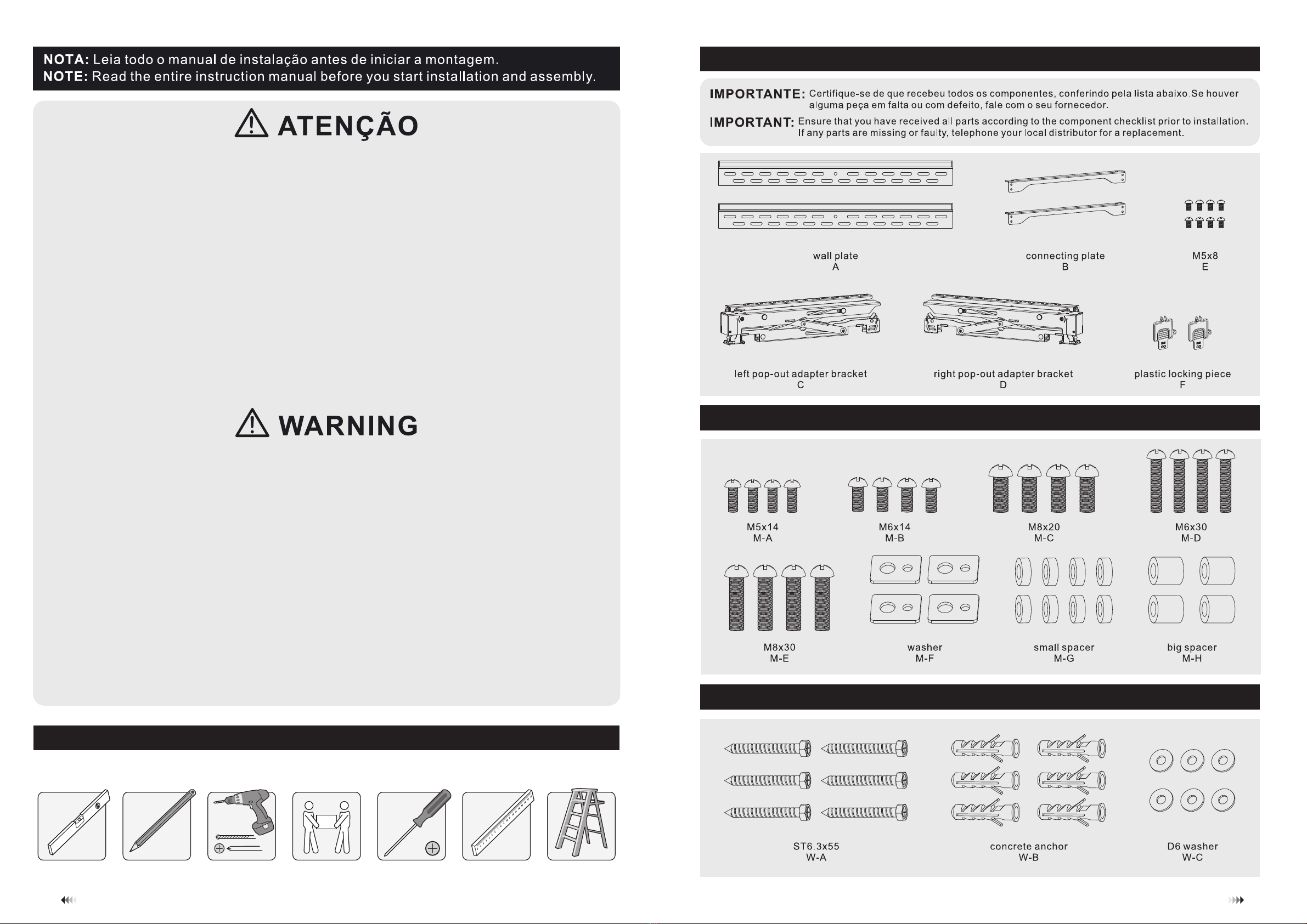
Lista de componentes / Component Checklist
Embalagem / Package M
Embalagem / Package W
placa de parede
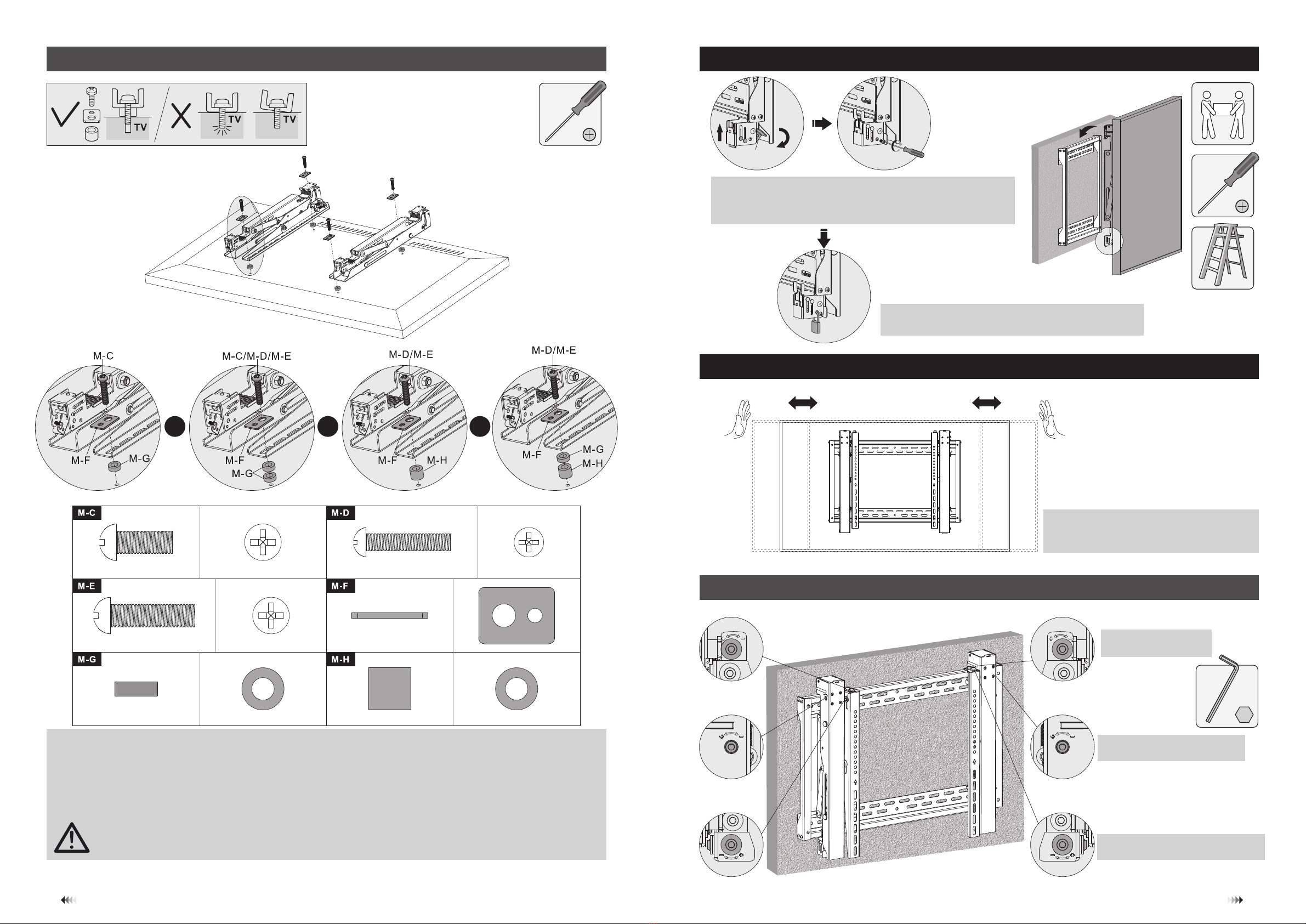
haste pop-out esquerda
anilha espaçador pequeno espaçador grande
anilha D6bucha de cimento
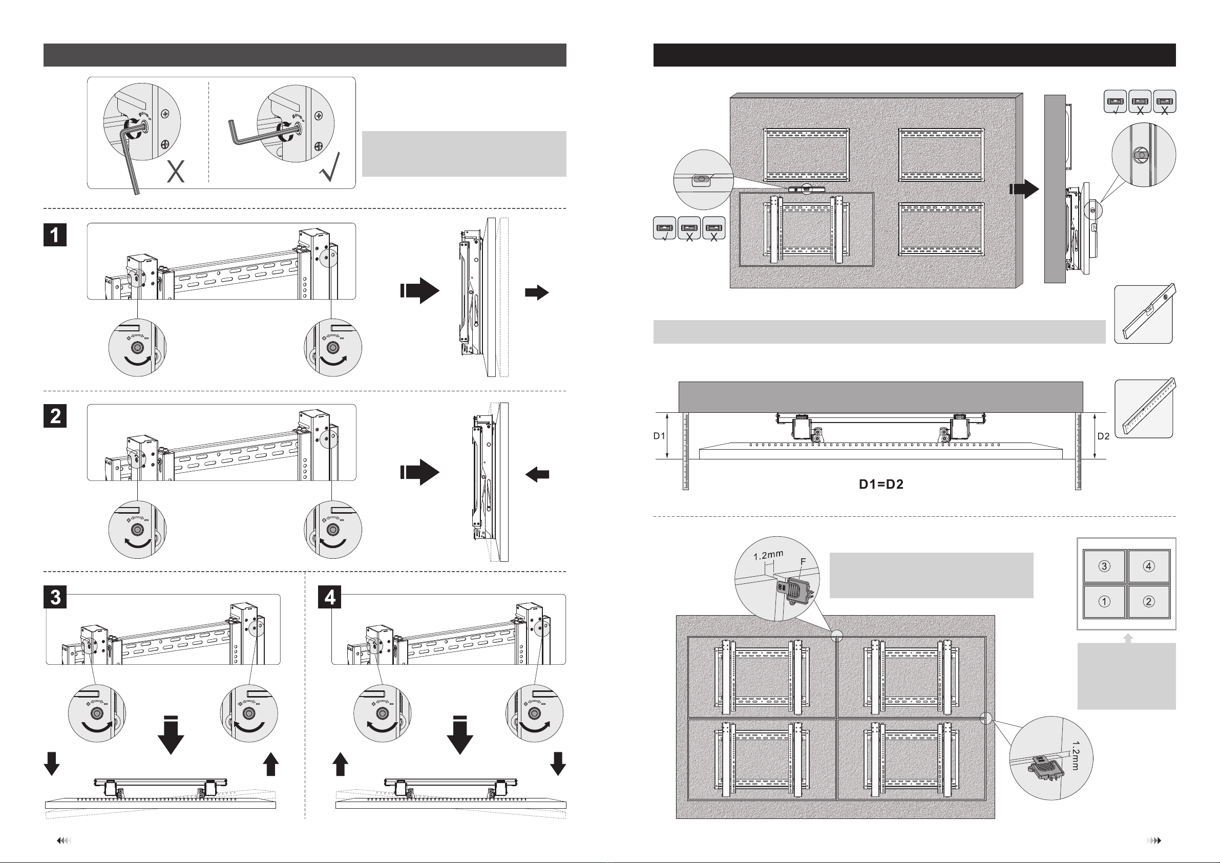
haste pop-out direita travão plástico
conector de placas
1. Dimensões do produto / Product Dimensions
3
4
2. Instalação do videowall / Video Wall Installation
X = Largura da TV / Length of display
Y = Altura da TV / Height of display
ATENÇÃO / WARNING
3. Montagem da placa de parede / Assembling the Wall Plate
Fixe as placas de conexão às placas da parede usando os parafusos apropriados.
Attach the connecting plates to the wall plates using the appropriate screws.
5
6
Screw the wall plate
onto the wall.
Fixar o suporte
à parede.
• Certique-se de que a superfície de suporte irá suportar com segurança o peso combinado do
equipamento e todo o hardware e componentes anexados.
• Installers must verify that the supporting surface will safely support the combined weight of the
equipment and all attached hardware and components.
4. Instalação em Parede de Tijolo ou Cimento / For Solid Brick and Concrete Wall Mounting
Drill pilot holes
Faça guias para
os parafusos
Find and mark the exact
location of mounting holes.
Marcar a posição dos furos.
X = Largura da TV / Length of display
Y = Altura da TV / Height of display
Allen Key
Chave Allen
Ball Joint
Junta esférica
Remove the Allen Key from the pop-out
adapter brackets.
Remover a chave Allen das hastes.
5. Instalação das hastes pop-out / Installing the pop-out adapter brackets
5-1 Para TV com as costas regulares / For Flat Back Screens
Pressione a haste até a junta esférica encaixar na sua posição. / Push the pop-out arm until the ball joint snaps into place.
Para VESA 600x400, trocar a posição de “C” com “D”. / For VESA 600x400, the positions of “D” and “C” are exchanged.
7
8
Note: With the arrow pointing up.
Nota: Seta a apontar para cima.
Top of the display
Topo da TV
Top of the display
Topo da TV
Travões
Locking plate
5-2 Para TV com as costas irregulares / For Bump-out or Recessed Back Screens 6. Conectando a TV à placa de parede / Hooking the display onto the Wall Plate
6. Ajustes / Adjustment
6. Micro-Ajustes / Micro Adjustment
ou
or ou
or ou
or
9
10
Nota: Escolha os parafusos, anilhas e espaçadores adequados (se necessário) de acordo com o tipo de tela.
Posicione as hastes do suporte o mais próximo possível do centro da TV.
Aparafuse as hastes do suporte na TV.
Note: Choose the appropriate screws, washers and spacers (if necessary) according to the type of screen.
Position the adapter brackets as close as possible to the center of the display.
Screw the adapter brackets onto the display.
Aperte todos os parafusos, mas não aperte demais.
Tighten all screws but do not over tighten.
Vire os travões para baixo para fixar as hastes e aperte os
parafusos para as prender.
Turn the locking plates downward to fasten the wall plate and tighten the screws
to secure them.
Utilize um cadeado para prevenir roubos (Não incluído)
Use a padlock to prevent the display from being stolen (Not included)
Empurre a tela para a esquerda ou direita para
ativar o alinhamento rápido.
Push the display to left or right to enable fast alignment.
Para regular a inclinação.
For tilt adjustment.
Para micro-ajustes (dentro e fora).
For micro-adjustment (in and out).
Para micro-ajustes (esquerda e direita).
For micro-adjustment (left and right).
Ajuste de inclinação / Tilt Adjustment Ajuste de altura / Height Adjustment
11
12
13
14
Ajuste de profundidade / Depth Adjustment 8. Nívelar as TVs / Level the Displays
Parede / Wall
Parede / Wall
Nota: Não utilizar a parte curta da chave Allen para
apertar os parafusos de ajuste. Use a parte longa.
Note: Don’t use the short end of Allen key to
tighten the adjustment screw. Use the long end.
Nota: Utilize a peça plástica para medir e manter
a distância de 1.2 mm entre TVs.
Note: Use the plastic locking piece to measure and keep
a 1.2 mm gap between displays.
Nota: Intale/ajuste o
número de TVs pela
ordem identificada.
Note: Install/adjust the
displays by the numerical
order given.

Other Napofix TV Mount manuals

Napofix CL400M User manual

Napofix

Napofix CL400M User manual

Napofix CL600M User manual

Napofix

Napofix CL600M User manual

Popular TV Mount manuals by other brands

Eaton OSHPD Install instructions

Eaton

Eaton OSHPD Install instructions

ricoo S2644 Assembly manual

ricoo

ricoo S2644 Assembly manual

ONKRON M2S user guide

ONKRON

ONKRON M2S user guide

FlowLine LM50 Series owner's manual

FlowLine

FlowLine LM50 Series owner's manual

Digital Watchdog NightWatch DW-ILWM3 quick start guide

Digital Watchdog

Digital Watchdog NightWatch DW-ILWM3 quick start guide

Cabletech UCH0200 user manual

Cabletech

Cabletech UCH0200 user manual

ACT AC8370 installation manual

ACT

ACT AC8370 installation manual

Blackbe;rry RADAR-M ITA100-1 installation guide

Blackbe;rry

Blackbe;rry RADAR-M ITA100-1 installation guide

Edbak WSTD-STDV100 instruction manual

Edbak

Edbak WSTD-STDV100 instruction manual

Omnimount LEDP75 instruction manual

Omnimount

Omnimount LEDP75 instruction manual

CHIEF MSB-6309 installation instructions

CHIEF

CHIEF MSB-6309 installation instructions

Stell SHO 1043 Assembly instructions

Stell

Stell SHO 1043 Assembly instructions

KSL WM111N installation instructions

KSL

KSL WM111N installation instructions

Bretford MSP-W5 Assembly instructions

Bretford

Bretford MSP-W5 Assembly instructions

Mustang MPA-M22VF instruction manual

Mustang

Mustang MPA-M22VF instruction manual

Techly ICA-LCD 114WH user manual

Techly

Techly ICA-LCD 114WH user manual

Yamaha UB2108 owner's manual

Yamaha

Yamaha UB2108 owner's manual

Brasforma SBRP1650 instruction manual

Brasforma

Brasforma SBRP1650 instruction manual

manuals.online logo
manuals.online logoBrands
  • About & Mission
  • Contact us
  • Privacy Policy
  • Terms and Conditions

Copyright 2025 Manuals.Online. All Rights Reserved.