NARGESA MC650 User manual

INSTRUCTIONS BOOK
PRADA NARGESA, S.L
Ctra. de Garrigàs a Sant Miquel s/n · 17476 Palau de Santa Eulàlia (Girona) SPAIN
Tel. +34 972568085 · [email protected] · www.nargesa.com
SECTION BENDING MACHINE
MC650
NS: 2022-346

Thank you for choosing our machines
www.nargesa.com

INDEX
1. MACHINE DETAILS ........................................................................................................... 3
1.1. Machine identification details ................................................................................... 3
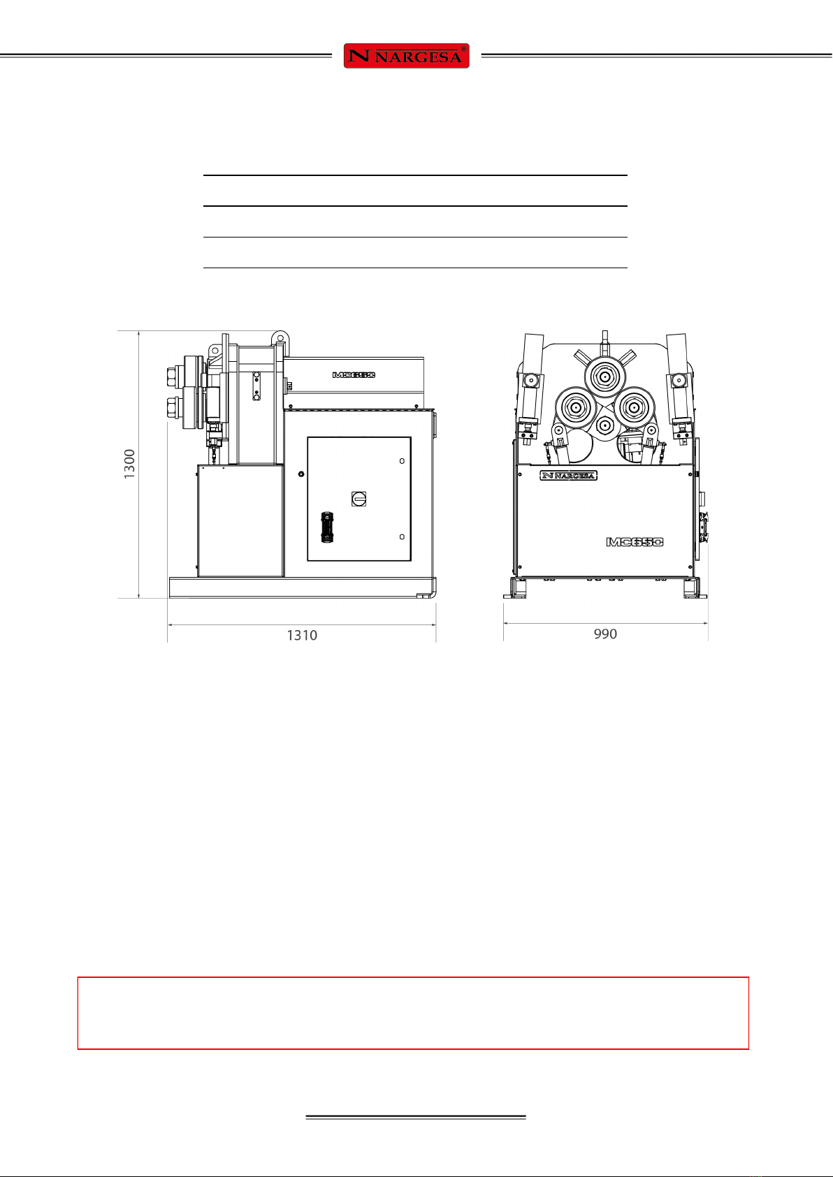
1.2. Dimensions .............................................................................................................. 3
1.3. Description of the machine ...................................................................................... 3
1.4. Machine part identification ....................................................................................... 4
1.5. General characteristics ............................................................................................ 5
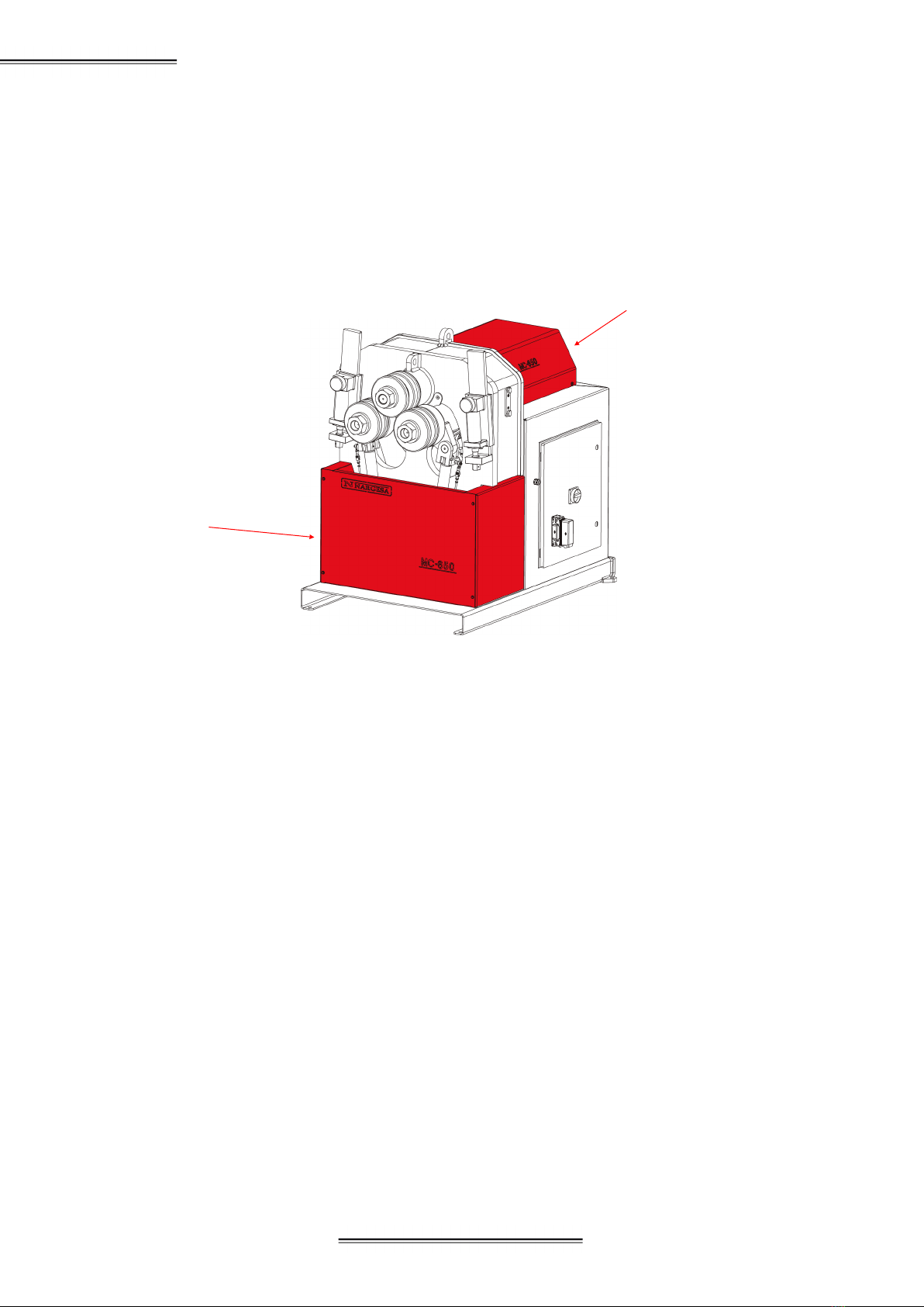
1.6. Description of the guards ......................................................................................... 6
2. TRANSPTRANSPORT AND STORAGE ........................................................................... 7
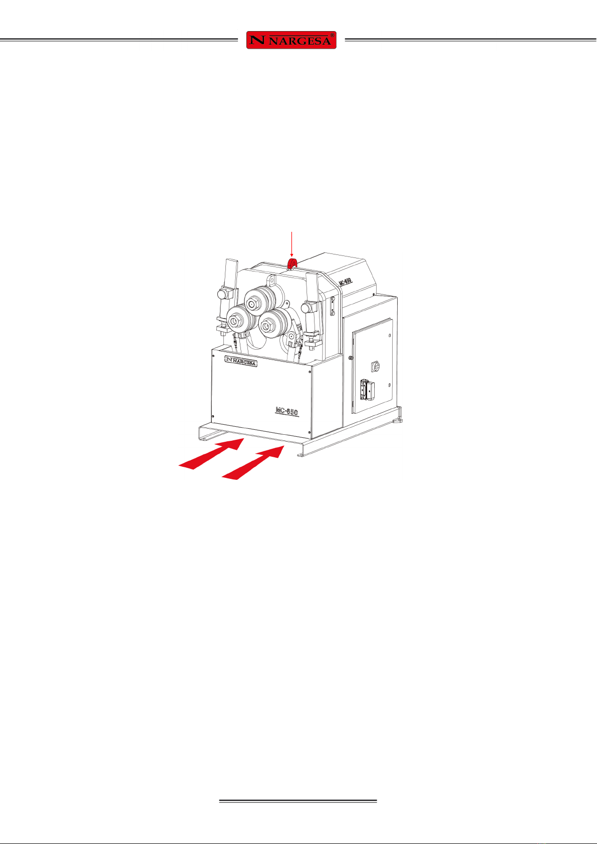
2.1. Transport .................................................................................................................. 7
2.2. Storage conditions ................................................................................................... 7
3. MAINTENANCE ................................................................................................................. 8
3.1. Lubrication of moving parts ...................................................................................... 8
3.2. Lubrication of straigthener arms …………………………………………………….…. 8
3.3. Hydraulic oil change ………………..……………...……………………………………. 9
3.4. Ckeckup of hydraulic instalation …………………..………………………………… 10
4. INSTALLATION AND START UP .................................................................................... 11
4.1. Positioning the machine ......................................................................................... 11
4.2. Dimensions and work area .................................................................................. 11
4.3. External permisible conditions ............................................................................... 11
4.4. Instructions for connecting to the power supply ..................................................... 12
5. INSTRUCTIONS FOR USE ......................................................................................... 16
5.1. Bending principles ….............................................................................................. 16
5.2. Assembly of the rollers ........................................................................................... 16
5.3. Instruction manual .................................................................................................. 17
5.3.1. Manual operating mode…………………………………………………….. 17
5.3.2. Automatic operating mode ………………………………………………… 19
5.3.2.1. General Data …………………...………………………………… 20
5.3.3. Using the Programs ……………………………………………………… 23
5.3.4. Creating a New Program ………………………………………………….. 25
5.3.5. Production Mode ………………………………………………………… 28
5.3.6. Using Materials and Tools …………………………………………….….….. 31
5.3.7. Importing and Exporting Data ………….………………………………….. 34
5.3.8. Using the Alarms ………….………………………….…………………….. 35
5.4. Working position ……………...………………………………….…………………… 37
6. WARNINGS ...................................................................................................................... 39
6.1. Residual hazards ................................................................................................... 39
6.2. Counter-productive methods .................................................................................. 39
6.3. Other recommendations ........................................................................................ 39
7. ASSEMBLY OF THE ROLLERS ...................................................................................... 40
7.1. Bending capacity .................................................................................................... 41
8. OPTIONAL ACCESSORIES ............................................................................................ 42
TECHNICAL ANNEX

- 3 -
1. MACHINE DETAILS
1.1. Machine identification details
1.2. Dimensions
Picture 1. External dimensions of the MC650 bending machine
1.3. Description of the machine
The MC650 bending machine is a machine specifically designed for bending profiles, the majority of which
are metal, with different thicknesses and configurations, such as solid profiles, pipes, T-profiles, angles...
The bending machine offers a set of standard tools, rollers, to allow the bending of profiles in a range of
shapes and sizes.
Apart from the standard rollers, the manufacturer also offers different types of additional rollers to produce
other types of bending, according to the configuration of the material to be handled, as well as specific
rollers for work with stainless steel or aluminium, manufactured with * SUSTARIN for jobs in stainless steel
or aluminum avoiding the material to be damaged or scratched.
* Sustarín: Polyoxymethylene, high resistance and high rigid crystalline thermoplastic, low friction and excellent dimensional stability
PRADA NARGESA S.L. is not liable for any damage that might occur due to misuse
or failure by users to comply with the safety standards.
Trademark Nargesa
Type Section bending machine
Model MC650

- 4 -
SECTION BENDING MACHINE MC650
1.4. Machine part identification
* Upper main roller
Straightener roller
* Lower main rollers
Straightener guide nut
Hydraulic cylinder
Control panel
* Bending rollers
Nuts to secure the position
of the straightener roller
Anti-rotation plate of the
straightener
Main switch
Connector
Anchoir point
for lifting
Anchor point for horizontal
position rotation
Hydraulic assembly
Oil level sight glass
Adjustment nut for
Back cover
of motor

- 5 -
Figure 2. Nameplate
1.5. General characteristics
Hydraulic unit features
Motor power 3 Kw / 4 CV to 1400 r.p.m.
Intensity 12 / 7 A
Voltage supply 230/400 V 3 phased
Traction 3 rollers
Rollers speed 5 r.p.m.
Diameter of rollers 202 mm
Diameter of axis Lower 65 mm / Higher 80 mm
Useful axis length 160 mm
Structure material Sheet
Weight 1250 Kg
Dimensions 1300x990x1300 mm
Motor power 0.75 Kw/1 CV a 1400 r.p.m.
Intensity 3.5 / 2 A
Pump 1,5 l/min
Work pressure 200 bars

- 6 -
SECTION BENDING MACHINE MC650
1.6. Description of the guards
The gear motor and all the gears that allow the operation of the machine are located under the main upper
cover that protects the mechanisms.
Although the major mobile elements are protected by the upper cover, it is necessary to take special
precautions during bending operations in order to avoid entrapment between the rollers and the piece
being bent.
Figure 3. Mechanism protection guards
Protection
drive unit
Frontal
protection

- 7 -
2. TRANSPORT AND STORAGE
2.1. Transport
There are two ways of carrying out the transportation of the machine:
- From the bottom, through the base of the machine, using a pallet jack or forklift as shown in the illustra-
tion. Never raise the machine more than 200 mm from the surface in order to prevent the risk of tipping
- From the top of the machine, from the anchor point designed for this purpose defined in figure 4, using a
crane or forklift.
Figure 4. Transportation of the machine
2.2. Storage Conditions
The bending machine shouldn’t be stored in a place that does not meet the following requirements:
- Humidity between 30% and 95%
- Temperature of -25 °C to 55 °C or 75 °C for periods not exceeding 24hrs
(remember that these temperatures are in storage conditions)
- Machines or heavy objects should not be stacked on top
Anchoir point for lifting

- 8 -
SECTION BENDING MACHINE MC650
CAUTION: The "Emergency Stop" push button must be pressed and the machine brought to a stop in
order to lubricate the machine”.
3. MAINTENANCE
3.1. Lubrication of moving parts
It is advisable to keep clean the machine moving parts, whenever posible, in order to ensure a correct per-
formance and thus make its useful life longer.
In order to lubricate the moving parts of the machine that require lubrication, it’s recommended to follow the
next instructions:
- Clean the surface to be lubricated with a cotton cloth or a soft rag that does not release any threads. To
remove the accumulated grease and any possible residues that have become stuck to it.
- After cleaning, reapply grease onto the surface with the help of a rag or a spatula.
- Spread the grease evenly without creating excesses or clumps.
- Lubricate the machine regularly, according to use.
* It is recommended to use lithium grease for the rollers N.850 EP-2.
3.2. Lubrication of straigthener arms.
In order to carry out the lubrication of the straigtheners:
1. we’ll place the rollers at the lowest position of the guide..
2. Then we clean and lubricate the guide.
Lubrication of the strraigthener guide.

- 9 -
3. We’ll put the roller up and lubricate its axis
4. We repeat three times the operation of moving the roller up and down so the grease can be properly
distributed along the surface.
Lubrication of the roller axis
5. We clean and lubricate the rear guide and place it in its máximum front point.
6. We move the guide frontwards and backwards so the grease is properly distribute along the surface.
Engrase de la guía trasera
3.3. Hydraulic oil change
To replace the hydraulic oil, we recommend to follow the steps below:
- Check the oil level in the tank every 500 hours of use, checkup the oil level in the hydraulic tank located in
the base inner side. In order to have a correct information about the oil level, the inner lower rollers must be
in their lowest position.
- The oil cap is located at the top of the tank. If it is necessary to add oil, fill to the level of the sight glass
at the front of the tank.
- Change the hydraulic oil in the tank every 2000 hours of work or every 5 years.
- Remove the old oil in a tray and dispose of it at the nearest recycling point.

- 10 -
SECTION BENDING MACHINE MC650
- Fill the tank with new hydraulic oil to the level of the sight glass located at the front. The capacity of the
tank is approximately 13 litres.
- Return the hydraulic assembly to its location and secure it to the machine with the
bolts.
* We recommend the use of CEPSA HIDRÁULICO HM 68 hydraulic oil.
Identification of the components of the hydraulic set.
3.4. Checkup of hydraulic installation
Every 6 months we should make sure there is no arising oil leak in the hoses of the hydraulic circuit.
Hoses of hydraulic circuit.
Refilling cap
Hydraulic tank
Oil level peephole

- 11 -
4. INSTALLATION AND START UP
4.1. Positioning the machine
Locate the machine properly in order to avoid moving it; otherwise, follow the guidelines described in the
paragraph transport (no. 2). Must be placed on a flat, level surface to prevent it vibrating and moving during
bending operations.
It is optional to fix the machine by the four bolts since it is provided with a lower base or stand with four per-
forations as it’s shown in Figure 5.
Figure 5. Anchor points of the machine
4.2. Dimensions and work area
The dimensions must be considered when the machine is being placed, the working area for the operator
and the possible lengths of the parts to be worked.
The bending machine can be used by a single operator, who must be directly in the front of the machine to
be able to handle the piece being bend with safety, and never on the side.
Prior to commencing the bending operation, with the machine shut down, the operator must adjust the
Figure 6. Operator's working area
4.3. External permissible conditions
It is advisable to work under the following atmospheric conditions:
- Room temperature between +5 °C and +40 ºC without exceeding an average temperature of +35 °C
within 24 hrs.
- Humidity between 30% and 90% without water condensation.

- 12 -
SECTION BENDING MACHINE MC650
IMPORTANT: This machine must be connected to an electrical outlet with earthing contact.
4.4 Instructions for connecting to the power supply
IMPORTANT: This machine must be connected to a 400V or 220V source with grounding contact The
MC650 is equipped with two 230V / 400V three-phase motors of 3 Kw and 1Kw connected in star or delta
in order to connect to a 400V or 220V source. It should be connected to an only power source and to the
indicated power source. If the line voltage is not as indicated: the machine's frequency inverters ARE NOT
MULTI-VOLTAGE, so if we have to change the voltage, the inverters must be replaced depending on the
supply voltage. At the same time, we will have to change the connection of the hydraulic group motor coils
as indicated below:
Changing the motor connection:
When the power supply is 400 V three-phase, connect in Star form (as preinstalled at the factory).
If the power supply is 230 V three-phase, proceed to connect in Triangle form. As indicated in the
illustration.
The connections are modified in the motor connection box, located inside the machine, changing the
configuration of the plates according to the mains voltage.
Figure 7. Change of engine
connections
Triangle figure
For voltage 230V
Star figure
(Default)
For voltage 400V
Before making any changes to the wiring of the motor bobbins or electrical panel, it is essential
to check that the machine is not connected to any power source.

- 13 -
Changing the hydraulic motor connection:
The motor of the hydraulic system is located inside the cabinet, at the bottom of the machine.
The hydraulic assembly is inside the cabinet. The motor is secured to the tank and on its front is the
connection box.
The same as the main motor, when the mains voltage is 400 V three-phase, proceed to connect in Star
form (as preinstalled at the factory). If the power supply is 230 V three-phase, proceed to connect in
triangular form. As indicated in the illustration.
It is necessary to change the configuration of the plates according to the voltage, as was done with the
main motor.
Figure 8. Changing the hydraulic engine connections
Triangle figure
For voltage 230V
Star figure
(Default)
For voltage 400V
We recommend contacting the Technical Service Department of NARGESA S.L.
if you wish to change the operation voltage of the machine in order to be guided and assisted
through the procedure.

- 14 -
SECTION BENDING MACHINE MC650
Triangle figure
For voltage 230V
Triangle figure
For voltage 230V
The MC650 bending machine comes equipped with a 230V/ 400V 3Kw three-phase motor for the operation
of the rollers and a 230V/ 400V 0.75 Kw three-phase motor to regulate the hydraulic piston, both ready to
be connected to a 1 phase 230V power supply. The machine must be connected with the plug installed to a
compatible power supply that meets the requirements specified.
Figure 10. Engine connections
The hydraulic system motor is located in the inside of the cabinet, at the base of the machine.
The hydraulic group is located inside the cabinet, with the motor secured to the tank and the terminal box
located at the front of the machine.
Figure 11. Changing the hydraulic engine connections

- 15 -
5. INSTRUCTIONS FOR USE
5.1. Bending principles
The bending of the different profiles and tubes is carried out by passing the material through the three
driven rollers located at the front of the machine. Out of these 3 rollers, there is one fixed, and the
remaining two are moveable. In this way and depending on the relative position of these three elements, it
is possible to achieve the desired radius.
In order to move the aforementioned rollers, there is a bench with a touch panel, as well as an orange
safety button and a 4-way joystick. The button and the joystick are located one on each side of the bench
and it is necessary the joint intervention of these two elements, to carry out any movement with the
machine. So, we prevent from any accident to occur because the operator will always have both hands on
the control panel when the bending machine is in motion.
The aforementioned button also has a pilot light indicating when it is possible to activate it. Thus, pressing it
with the indicator off will not give the machine any order.
All the other information necessary to give any command to the bending machine and receive information
from it, is done through the touch panel also located on the table. Through this element it is possible to
operate the machine manually or automatically, select the different traction rollers, create and execute
programs, save and load programs, enter information about the bending (material, rollers used, height,
width, thickness, …). In addition, all the alarms and possible errors also appear in this interface, which
comes to be very useful to know what is happening at all times
5.2. Assembly of the rollers
Figure 12. Position of the rollers in relation to the machine axes

- 16 -
SECTION BENDING MACHINE MC650
5.3. User guide
A control panel with a multi-function touchscreen is used to operate the MC650 hydraulic pipe bender. The
machine can also be controlled with a movement button and a four-way joystick for easier roller positioning.
The control panel also features an emergency stop and a voltage indicator light.
1. Multi-purpose touchscreen
2. Movement button
3. Four-way joystick
4. Emergency stop
5. Voltage indicator light
2
1
3
45

- 17 -
This is largely the man/machine interface. However, reading the steps indicated in the following sections
is recommended in order to be able to work with the machine safely and comfortably.
5.3.1. Manual operating mode
After turning on the power to the machine (“Power On”), the manual mode graphic interface is
displayed on screen.
The active operating mode is identified by the horizontal bar drawn below one of the two central images
(automatic and manual) shown in the vertical menu in the right-hand side of the display.
The message bar at the top shows useful information and alarms so the user may know the machine
status at all times.
The chosen language identification flag and the current time are shown at the top right.
The layout of the machine rollers along with the current height are shown in the middle of the graphic area
above the speed control bar.

- 18 -
SECTION BENDING MACHINE MC650
The bottom of the screen is reserved for the active mode horizontal menu buttons.
In view of the message that appears at the top, the system must be reset in order to work appropriately. To
do so, press the button on the horizontal menu. If you do this, the message will disappear and the mo-
vement button indicator light on the front of the control panel will light up.
The bending machine is factory-set in eco energy savings mode is to reduce consumption to a minimum
when a period of inactivity is detected. This means the hydraulic pump will disconnect after a certain
amount of time without being operated. This is normal. Thus, the hydraulic pump will continue to be stop-
ped after the system is reset. Press the icon on the horizontal menu at the bottom to start it or simply
activate the movement button on the control panel.
Of the three rollers arranged in pyramid form on the bender, only the position of the two bottom ones can
be changed with the hydraulic activation of the two pistons. Thus, each one of them can be positioned in
the exact place for optimal bending.
In manual mode, the active roller is highlighted in red. The one on the left (roller X) or the one on the right
(roller Y) can be selected simply by pressing the corresponding drawing on the screen. Afterwards, to move
it, just press the movement button on the front of the control panel with one hand and move the position
joystick with the other up or down. During this action while the chosen roller moves physically, you can see
on screen how the current height changes.
If you want more control over the position of each one of these rollers, use the speed control. This is shown
on screen with this icon under the rollers.
Reducing the speed is recommended for precise roller positioning. This is done by pressing on the desired
segment of the aforementioned bar, which will then reflect the new percentage out of the total.
Speed at 10% Speed at 50% Speed at 100%

- 19 -
Besides the hydraulic movement of rollers X and Y which can change the pyramid-like triangle geometry of
the machine for different bending radiuses, the MC650 allows synchronized rotation of the three pull rollers
for optimal bending on the pieces to be produced.
To do so, just press the movement button again with one hand and move the position joystick with the
other to the left or right. In this case, it doesn’t matter which roller is selected. The three will rotate in the
desired direction simultaneously.
Likewise, as seen with the movement of rollers X and Y upwards and downwards, you can now use the
speed bar to increase or reduce the rotation speed. To do so, choose the right speed percentage as was
done before by directly touching the speed bar on the screen and bend the piece using the movement
button and direction joystick.
5.3.2. Automatic operating mode
To access the automatic bender operating mode, just press the icon on the vertical menu at the right
of the screen.
As can be seen in the image, the information on the screen has slightly changed with respect to manual
mode yet the graphic interface continues to be clear and intuitive.
Other manuals for MC650
2
Table of contents
Other NARGESA Cutter manuals
Popular Cutter manuals by other brands

Alpha tools
Alpha tools MF 1300 operating manual

Vector Welding
Vector Welding SIWM DIGITAL Paris700 operating instructions

SIRI
SIRI SIRIPRO 57 Operating and maintenance manual

iWeld
iWeld KOMBI30 instruction manual

EINHELL
EINHELL TH-MA 1300 Original operating instructions

Craftsman
Craftsman 183.172500 owner's manual