3 1-2017
Translation
CONTENTS
1.1
Foreword ...............................................................................................................................5
1.2
EU Declaration of Conformity.............................................................................................6
1.3
Intended use of the machine ...................................................................................................7
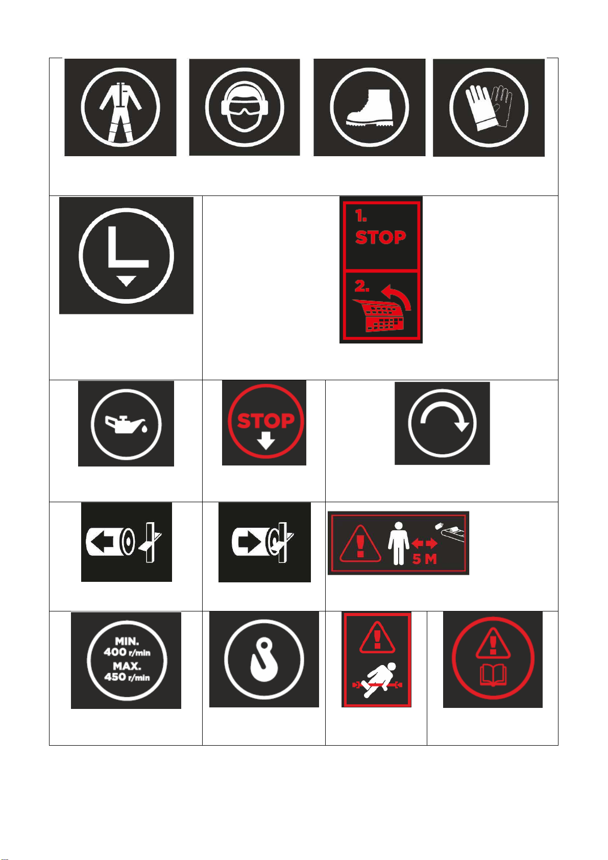
1.4
Warning signs.........................................................................................................................7
1.5
Nameplates...........................................................................................................................9
1.6
The main dimensions and models of the machine.......................................................10
1.7
Safety instructions..............................................................................................................10
1.8
Noise emission and vibration...........................................................................................11
1.9
Responsibilities of the operator .......................................................................................11
1.10
Operating conditions......................................................................................................12
1.11
Terms of warranty...........................................................................................................12
1.12
Operating instructions for the winch............................................................................12
2
Taking delivery and setting up the machine for operation..........................................13
2.1
Lifting the machine.............................................................................................................13
2.2
The transport set-up and unpacking...............................................................................13
2.3
Acceptance inspection......................................................................................................13
2.4
Main parts of the machine, Fig 1.....................................................................................13
2.5
Bringing the table extension into the work position, Fig. 2..........................................14
2.6
Bringing the conveyor into the work position, Figs. 3 and 4........................................14
2.7
Bringing the conveyor into the work position, Fig. 5.....................................................15
2.8
Adjusting the cutting length, Fig. 6..................................................................................16
3
Operation of the firewood processor powered by different power sources .............16
3.1
Testing the machine..........................................................................................................16
3.2
Powered by a tractor.........................................................................................................16
3.3
Suitable revolutions range for the PTO shaft ................................................................16
3.4
Disengagement lever for transmission, Fig. 7...............................................................17
3.5
Required measures in an emergency situation.............................................................17
3.6
Starting under cold conditions (machine powered by a tractor).................................17
3.7
Electric drive, start and emergency stop........................................................................17
3.8
Starting the electric motor using the Y/D starter, Fig. 8...............................................18
3.9
Emergency stopping of an electrically powered machine, Fig. 8.............................19
3.10
The machine is equipped with a system to prevent simultaneous operation in two
modes, Fig. 9................................................................................................................................19
3.11
Operation under cold conditions ..................................................................................19
3.12
Electric heater for oil tank..............................................................................................20
4
Full-hydraulic control.........................................................................................................20
4.1
Mastering the safety devices............................................................................................20
4.2
Joystick-valve, Fig. 10.......................................................................................................20
4.3
Other hydraulic operating controls, Fig. 11....................................................................21
5
Use of the firewood processor, crosscut operation .....................................................23
5.1
Operating the crosscut saw, before the operation........................................................23
5.2
During the operation..........................................................................................................23