NARIKA C15-2851-W0 User manual

Instruction manual
C15-2851-W0
High-accuracy Monkey & Hunter Set
July 2022

1
Safety Precautions
Do not disassemble, repair, and remodel this product. The warranty will be void.
Do not apply electric voltages over 4 V (maximum allowable input voltage) to the ball
release unit (hereinafter, BRU). Otherwise, the electromagnetic coil of the unit may
ignite and burn out.
This product is for a teacher's demonstration only.
Keep your students away from this product, especially, from the course of launched
ball during demonstration.
Should you find any defect in the product, do not repair it by yourself. Contact your
distributor.
Keep dry. Otherwise, the product can be damaged.
Do not use this product on an uneven surface.
Avoid direct sunlight and high temperatures.
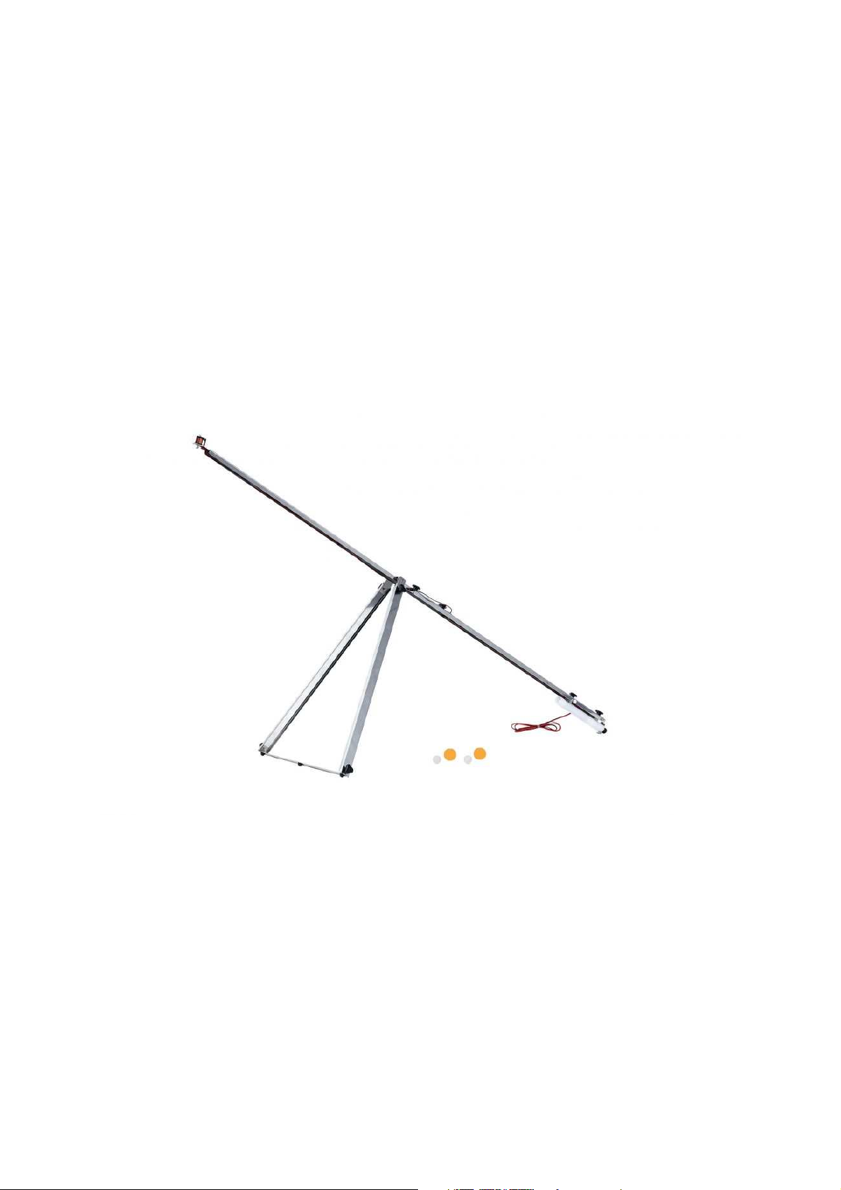
Product's Feature
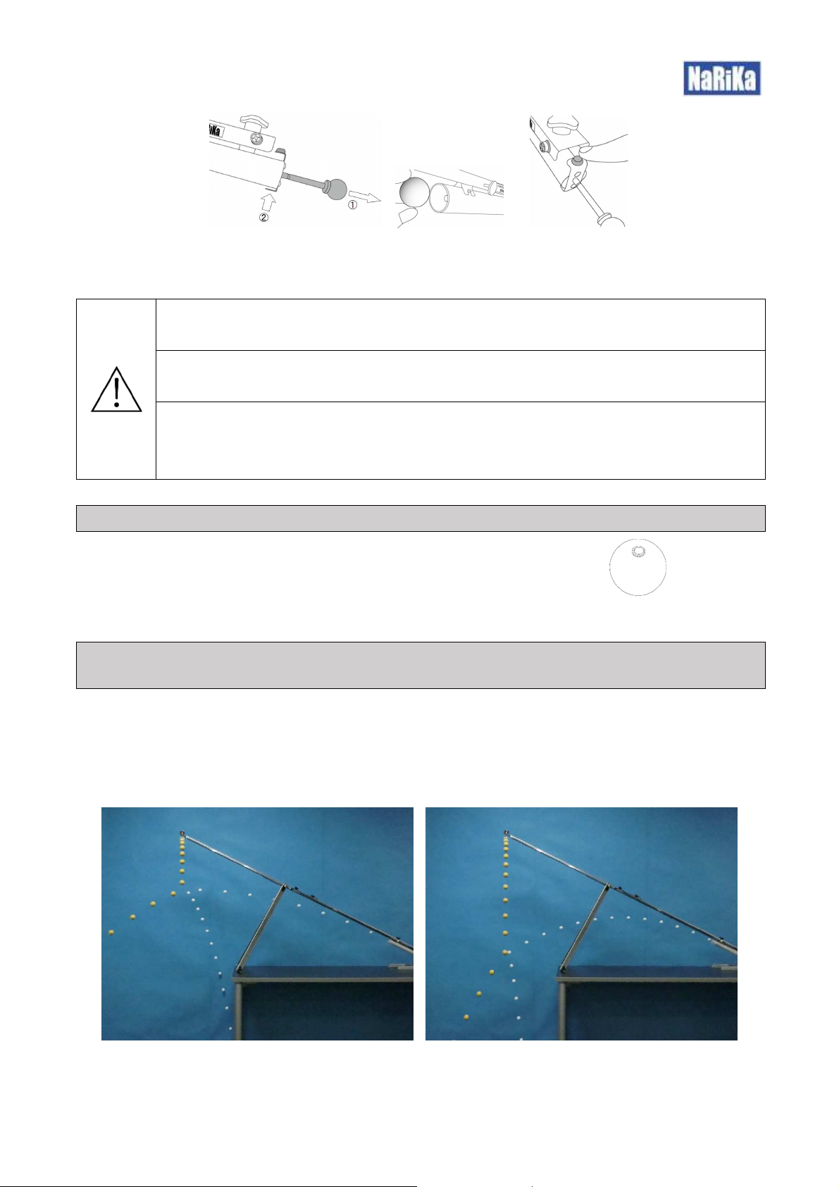
Compared with conventional type of apparatus, this product better demonstrates an essential and classic physics problem,
known as “the Monkey and the Hunter”, by providing students with high-accuracy collision of a projectile (an aluminum ball
used as a bullet shot by a hunter) with a free-falling object (a plastic ball used as a monkey falling from a tree). Achieved
highly accurate and repeatable collision of a small projectile (an aluminum ball of diameter 25mm) with a small free-falling
object (a plastic ball of diameter 35mm) over the airline distance of around 1500mm.
Specification
•Size after assembly (excluding a support stand): 1,900 × 570 × 720mm
•Boom: 1,900mm (the full-length rail after two rails is united with each other)
•Ball release unit: Electromagnetic type (Rated voltage: DC 2.5V, Maximum input voltage: 4.0V)
•Ball launcher: Spring plunger type
•Accessories:
oFree-falling object: φ35mm Plastic ball x2 pcs
oProjectile: φ25mm Aluminum ball x2 pcs
oMetallic ring-shaped plumb connected with a magnet via a kite string (1m) x1 pc
Required equipment (not included, prepare beforehand by yourself): a DC power supply (2.5V recommended, max. 4V,
5A), a support stand with a clamp to fix a supporting rod (8mm diameter).

2
Description of each part
Fig. 1 Assembled apparatus
How to set up
1.Securely unite the upper boom with the lower boom using two of screw with a built-in knob to assemble the full-length
boom.
2. Connect each of the built-in lead wires (red and black, one each) of the
lower boom, with each of the color terminals located along the sides of the
upper boom (red wire with red terminal, black wire with black terminal) to
complete assembling the boom (see Fig. 2).
Ball launcher
Ball release unit (BRU)
Boom (in full-length)
Bipod
Projectile
Free-falling Object
Fig. 2 Wire connection

3
3. Find the U-shaped bracket mounted on the upper boom. To fix each leg at a proper angle to the upper boom, slide
each leg fully into the U-shaped bracket and firmly screw it
with two screws with a built-in knob (see Fig. 3). If not
attached at first, slide the two legs into the bracket and fix
them by the screws.
4. Connect the brace with the other end of each leg using two
screws with a built-in knob to stabilize the bipod (see Fig. 4).
5. Use prepared support stand and a clamp. Insert and clamp the supporting rod part of the lower boom into the clamping
hole of the support stand. Thanks to this setting, the launching angle of a projectile will be adjustable by changing the height
of the clamp part of the support stand and the spring firing pin (SFP) will smoothly work.
Fig. 4 Bipod Fig. 5 Support rod with a support stand
How to use “Ball Release Unit (BRU)”:
BRU is equipped with a coil to electromagnetically suspend a “Free-falling Object” from the end of the boom (see Fig. 1).
In synchronization with triggering and releasing the spring firing pin, the power supply to the coil will cut off. Thus, BRU will
release the object simultaneously.
1. Prepare a DC power supply and make sure it is switched off. Connect the
built-in lead wires of Ball launcher (each of the red one and black one) to the
DC power supply (see Fig. 6 on the right).
2.
Grasp the knob of SFP, slowly take SFP from the barrel (①), and then,
latch SFP at one of its four equally spaced shallow cuts (grooves) (②) to determine the magnitude of launching the ball
(see Fig. 8).
3. Set the output voltages of the power supply to DC 3V and stick the free-falling object to the iron core of BRU in such a
way that the small steel part of the ball surface directly contacts with the iron core of BRU.
4.
Try to detect a threshold voltage value by slowly stepping down the voltage, at which BRU can no longer suspend the
Fig. 3 Assembling the bipod
Brace
Supporting rod part
(for adjusting firing angle)
Fig. 6

4
object electromagnetically. The threshold voltage value ought to be between 1.2 to 2.5V.
5. Set the output voltage slightly over the detected threshold so that the object can barely stick to the iron core.
Do not apply voltage exceeding DC 4V (maximum input voltage) to BRU.
Do not apply voltage well over the abovementioned threshold voltage value. Otherwise, electromagnetic
attraction generated by BRU will be too intense and residual magnetic flux will remain in the coil, due to
which BRU will release the free-falling object (plastic ball) delayed than theoretically expected.
How to use “Ball Launcher”:
Fig. 7 Ball launcher
Barrel is equipped with an actuator located on the inside of the barrel. In synchronization with triggering and releasing the
spring firing pin, designed to cut off a power supply to the coil of Ball Release Unit (BRU) to release a ball.
1. Grasp the knob of a Spring Firing Pin (SFP) , slowly take SFP from the barrel (①), and then, latch SFP at one of its four
equally spaced shallow cuts (grooves) (②) to determine the magnitude of launching the ball (see Fig. 8).
2. Attach a “Free-falling Object” beneath BRU in such a way that the small steel part of the ball surface directly contacts
with the iron core of BRU.
3. Put a “Projectile” in the barrel.
4. When pressing the trigger button of the ball launcher to release the spring firing pin, synchronously, power supply to the
coil of BRU will be cut off. Thus, the “Free-falling Object” will also be released simultaneously (see Fig. 8). As a result, the
projectile and the object will collide with each other.
Built-in lead wires (Red & Black, one each)
Barrel
Supporting rod (for adjusting firing angle)
Trigger / Stopper Button
Spring Firing Pin

5
Fig. 8 How to launch (fire) a Projectile
Do not look into the barrel or aim at something.
Make sure the area in front of the ball launcher is clear.
Pressing Trigger/Stopper Button only with index finger is highly recommended. Be careful not to catch
finger(s) in between the latch and the knob when SFP gets back.
Specification of “Free-falling Object”
Diameter 35mm
Material: ABS resin
Small steel part on the ball surface: An area for sticking the ball to the iron core of BRU. Fig. 9
Examples of the demonstration:
Below photos were filmed in rapid shooting mode of a high-speed camera and processed using graphic software. Photos
on the left are the stroboscopic images of the projectile launched with a greater magnitude, whereas those on the right
are the images of the projectile launched with a smaller magnitude.
1. Example of Projectile Trajectory (when the launch angle is around 40 degrees above the horizontal plane):

6
2. Example of Projectile Trajectory (when launched horizontally):
Troubleshooting
Note this is a factory-adjusted product that should work successfully without any adjustment on site. Nevertheless, in case
the projectile rarely hits the free-falling object, please carefully read the precautions again and go through the below
adjustment procedure as needed.
Do not disassemble the product.
1. How to adjust the launching angle in horizontal direction:
1. Find Metallic Ring-shaped Plumb (MRP) connected with a magnet via a kite
string in the product package.
2. Stick the magnet of MRP to the front of BRU to check the launching angle of
the barrel in horizontal direction.
3.
Launch a projectile from the ball launcher (without releasing the free-falling
ball) and check if the projectile hits the string of MRP.
4. In case the projectile rarely hits the string, determine on which side of
the string it travels.
5. Slightly (not fully) loosen the screw with a built-in knob further from the
trigger/stopper button above the barrel. Turn both of the knurled screws
along the side of the lower boom clockwise or counterclockwise.
For example, when adjusting the launching angle slightly to the left, [1]
loosen (unlock) the screw knob further from the trigger/stopper button, [2]
Screw
with built in
knob
Knurled screw
(Left)
Knurled screw
(Right)
Fig. 10
Fig. 11

7
loosen the knurled screw (left) counterclockwise, [3] tighten the knurled screw (right) clockwise as far as you can, and
then [4] tighten the screw knob to lock the barrel again.
Launch the projectile again to check if the projectile hits the string. If not, repeat above procedure.
6.
Only after making sure the projectile constantly hits the string, move to the next step to adjust the launching angle in the
vertical direction.
2-1. How to adjust the launching angle in vertical direction:
1. Remove MRP from BRU.
2. Set the output voltages of the power supply to DC 3V.
3.
Grasp the knob of SFP and slowly take SFP from the barrel. This automatically alters the built-in micro switch from the
off state to on state, which starts the power supply to the coil of BRU. The iron core of BRU becomes magnetized.
4. Latch SFP at one of its four equally spaced shallow cuts (grooves) and stick the “Free-falling Object” to the iron core of
BRU.
5. Lower the voltage of the power supplied to BRU and detect a threshold voltage value at which BRU can no longer
suspend the plastic ball electromagnetically (the threshold should be somewhere between1.2V and 2.5V).
6. Repeat above step 1 to 5 until determining the threshold out-put voltage. Once determining it, do not change the setting
of the power supply.
7. Check if launched projectile hits the free-falling object. If not, observe whether the projectile trajectory travels over the
free-falling object or beneath it.
8. If beneath, slightly lower the out-put voltage, so that BRU would bear less remanent magnetization* and the free-falling
object would be released more synchronously.
9. Launch the projectile again. If the projectile rarely hits the free-falling object, nevertheless, move to the next step below.
* Remanent magnetization of BRU may defer the releasing timing of the free-falling object.
2-2. How to adjust the launching angle in vertical direction:
Consider the following procedure as the last resort for a successful demonstration. If this procedure does not work, do not
adjust the product further and contact the distributor.
a) To adjust the launching angle upward: Slowly rotate a screw with a built-in knob (1) counterclockwise little by
little to increase the elevation angle of the barrel against the lower boom.

8
b) To adjust the launching angle downward: Slowly rotate a screw with a built-in knob (2) clockwise little by little
to decrease the elevation angle of the barrel against the lower boom.
Check if the projectile successfully hits the free-falling object.
Fig. 12
www.global.narika.jp
Screw with a built-in knob (1) (Closer to Trigger/Stopper Button)
Screw with a built-in knob (2) (Further from Trigger/Stopper Button)
Table of contents
Other NARIKA Industrial Equipment manuals
Popular Industrial Equipment manuals by other brands

HSB
HSB Gamma 90-ZSSD Original Assembly and Maintenance Instructions

M-system
M-system 10JFX instruction manual

rotork
rotork ILG/S Series Manual for Installation and Operating

ABB
ABB HT842192 Operation manual

schmalenberger
schmalenberger fluvo C2G rondo operating instructions

Stahls
Stahls Hotronix POWER PLATEN quick start guide