C
D
U
M
T
5. Assemble the frame hooks (E and F) as shown in Figures 4a,
4b and 4c. Note, each frame hook bracket is composed of two
plastic pieces (G) and a metal U-bracket (V). The metal
U-bracket should slide over and contain the two plastic pieces,
as shown in Figure 4a.
6. Slide the long frame hooks (E) onto the upright tubes with the
hooks facing away from the vehicle and tighten in place with the
locking knobs (J). See Figure 5.
7. Slide the short frame hooks (F) onto the upright tubes with the
hooks facing the vehicle and tighten in place with the
locking knobs (J).
8. Assemble the wheel hoops (H and I) as shown in
Figures 6a and 6b.
9. Slide the wheel hoops onto the platform tubes (B) as
shown in Figure 7.
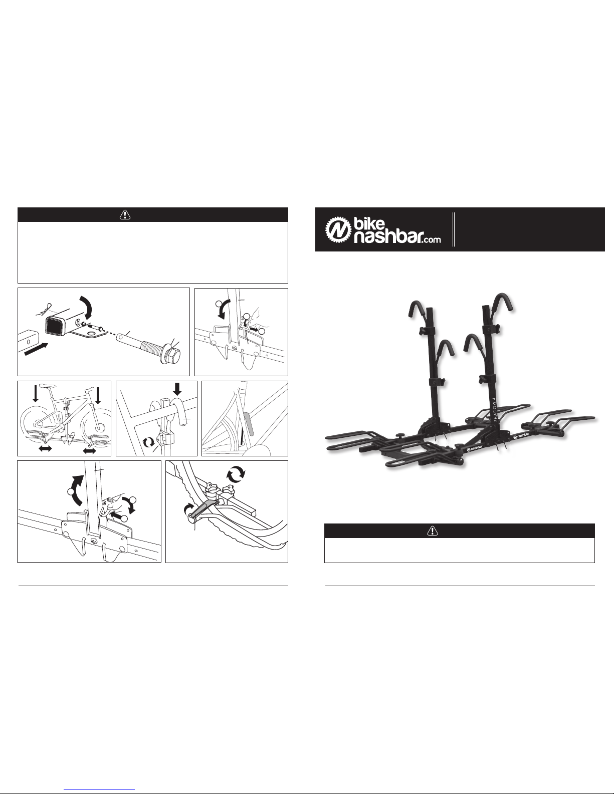
Installing the Hitch Rack
1. Slide the hitch tube into the vehicle receiver hitch and align the
bolt hole in the receiver hitch with the bolt hole in the hitch tube.
See Figure 8.
2. Slide the slotted (M) and flat (N) washers onto the hitch bolt
(L), thread the bolt through the receiver hitch and hitch tube,
and tighten securely.
3. Press the pin clip (O) through the hole in the protruding end of
the hitch bolt.
III. USING THE HITCH RACK
Loading the Bicycles
1. Remove the upright securing pins (S) and lower the
upright tubes (A). See Figure 9.
2. The first bicycle will be positioned closest to the vehicle. Lift the
bicycle into place, and set the front and rear wheels into the
wheel hoops (H and I). Each wheel should be well supported by
both ends of each hoop. See Figure 10.
3. Reposition the wheel hoops as necessary until both wheels
are well supported. Loosen the locking knobs (J), slide the wheel
hoops left or right along the platform tube, and re-tighten the
locking knobs securely.
4. Raise the upright tube and slide the frame hook (F) down until it
presses firmly against the bicycle’s top frame tube; then tighten
the locking knob (J) securely. See Figure 11.For bicycles with
sloping top tubes, position the bicycle so the hook is as low on
the sloping tube as possible. See Figure 12.
5. Replace the upright securing pin and rotate it clockwise as far as
it will go. See Figure 13.
6. Lift the second bicycle into place. Adjust the position of the
wheel hoops as necessary so that both wheels are well sup
ported and tighten the locking knobs. Slide the frame hook down
until it presses firmly against bicycle’s top frame tube; then
tighten the locking knob securely.
7. Secure the wheels of both bicycles with the hook and loop
straps at the end of each wheel hoop. See Figure 14.
8. Load the third and fourth bicycles in the same way, securing
them as described above.
9. Once all bicycles are secure, make sure no part of any bicycle
can contact and potentially scratch or otherwise
damage the vehicle.
Maximum Bicycle Limit:
4 bicycles
Maximum Load Limit:
35 lbs. per bicycle (140
lbs total)
Upright Tube ......................................... A ..........................2
Platform Tubes ..................................... B ..........................4
Hitch Tube ............................................ C ..........................1
Connection Tube .................................. D ..........................1
Long Frame Hook................................. E ..........................2
Short Frame Hook ................................ F ..........................2
Frame Hook Bracket (2 pcs)................. G ..........................4
Wheel Hoops ....................................... H ..........................4
Wheel Hoops ......................................... I ...........................4
Locking Knobs.......................................J..........................12
Wheel Straps........................................ K ..........................8
Hitch Bolt ...............................................L...........................1
Large Slotted Washer........................... M ..........................3
Large Flat Washer................................ N ..........................1
Pin Clip ................................................. O ..........................1
Hitch Tube Assembly Bolts................... P ..........................4
Small Slotted Washers ......................... Q ..........................4
Frame Hook and Wheel Hoop
Assembly Bolts..................................... R .........................12
Securing Pins ....................................... S ..........................6
Connection Bracket .............................. T ..........................1
Connection Tube Assembly Bolts ......... U ..........................2
Frame Hook U-bracket ......................... V ..........................1
II. ASSEMBLY
Assembling the Hitch Rack
Note: All references to left or right are from the driver’s perspective.
1. Remove the hitch rack and all other contents from the box.
2. Attach the connection tube (D) to the hitch tube (C) using
the connection bracket (T), assembly bolts (U) and slotted
washers (M) as shown in Figure 1a. Tighten the bolts securely.
3. Remove the platform securing pins (S) from the platform tubes
(B), fold down the left and right platform tubes and replace the
securing pins. See Figure 2.
4. To attach the upright tubes (A) to the connection tube (D), slide
the ends of the connection tube into the brackets at the base
of each upright tube (A). See Figure 1b. Thread the assembly
bolts (P) with washers (Q) through the bolt holes, and tighten
securely. See Figure 3.
LMN O PQRU
I. PARTS LIST
PART PART CODE QUANTITY
Do not exceed the maximum bicycle limit or maximum load
limit listed in this owner’s manual. Consult vehicle owner’s
manual to determine maximum tongue weight (TW) for vehi-
cle. Do not use rack if combined weight of rack (72 lbs) and
bicycles exceeds vehicle’s maximum tongue weight.
CAUTION
Assemble and install rack using hand tools only.
Do not over tighten. Do not use power or pneumatic tools.
CAUTION
Fig 1
1
2
3
A
P
Q
C
D
A
P
Q
Fig 1A
Fig 1B
Fig 2
P
Q
17mm
R
J
R
R
H&I
H
I
H
I
H
I
H
I
R
J
F
J
G
A
G
E
J
E&F
G
V
Fig 3
Fig 4A
Fig 4B
Fig 4C
Fig 6A
Fig 5
Fig 6B
Fig 7