Nastec MIDA 203 Guide

Installation and use manual
MIDA
manMIDA_eng_10

2
Index
1. MIDA Introduction ............................................................................................................................................................ 3
2. Safety Instructions............................................................................................................................................................. 3
3. Technical Characteristics ................................................................................................................................................... 4
3.1 Performance ............................................................................................................................................................................ 4
3.1 Weight and dimensions .......................................................................................................................................................... 4
3.2 Cable entries ............................................................................................................................................................................ 4
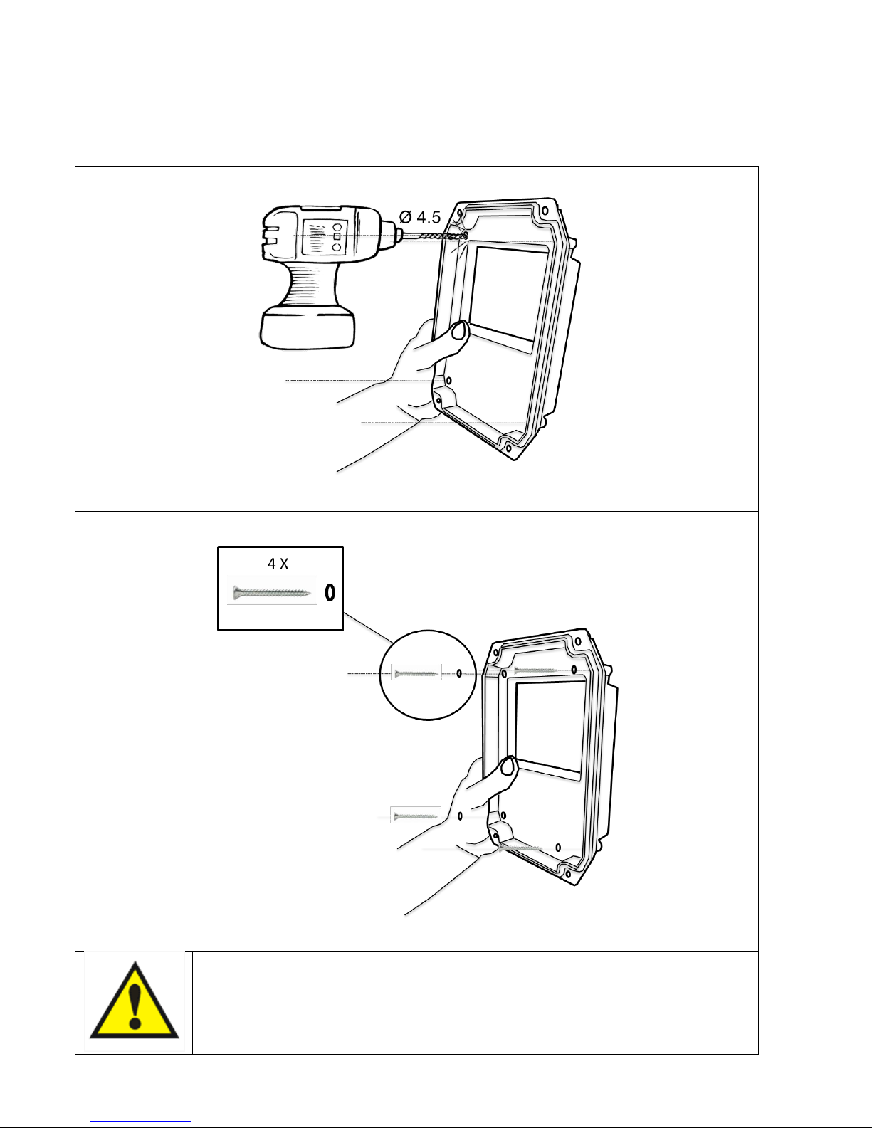
4. MIDA installation .............................................................................................................................................................. 5
4.1 Mechanical installation ............................................................................................................................................................ 5
4.2 MIDA Installation for constant pressure control ..................................................................................................................... 7
4.2.1 Pressure tank ................................................................................................................................................................ 7
4.2.2 Pressure sensor............................................................................................................................................................. 7
4.3 MIDA installation for differential constant pressure applications ........................................................................................... 8
4.3.1 Sensors wiring ............................................................................................................................................................... 8
4.3.2 Programming................................................................................................................................................................. 8
5. Electric wiring.................................................................................................................................................................... 9
5.1 Protections............................................................................................................................................................................. 13
5.2 Electromagnetic compliance.................................................................................................................................................. 13
5.3 Installation with long motor cables ....................................................................................................................................... 13
6. MIDA use and programming.............................................................................................................................................14
6.1 Monitoring and programming............................................................................................................................................... 15
6.1.1 Monitoring ................................................................................................................................................................. 15
6.1.2 Programming.............................................................................................................................................................. 16
6.2 COMBO operation.................................................................................................................................................................. 23
7. Protections and alarms.....................................................................................................................................................25

3
1. MIDA Introduction
MIDA is a variable frequency drive (inverter) designed to control and protect pumping systems by varying the output
frequency to the pump.
MIDA can be applied to both new and existing pumping systems providing:
energy and cost savings
simplified installation and an overall lower pumping system cost
longer life of the pumping system and relevant components
improved reliability
MIDA, when connected to any pump, manages the system operation to maintain a certain constant physical quantity
(pressure, differential pressure, flow, temperature, etc.) regardless of water demand. The pump is operated only when
needed thus avoiding unnecessary energy consumption.
MIDA at the same time is able to:
protect the motor from overload and dry running
implement soft start and soft stop to increase the system life and reduce current peaks
provide an indication of current consumption, voltage, and power
maintain a record of run time and display any errors and/or failures reported by the system
connect to other MIDA units for combined operation
MIDA can be installed on motor terminal box or fixed on the wall.
In the last case, through the use of output filters it is possible to reduce dangerous surges that are induced in long cables,
making MIDA suitable for control also of submersible pumps.
2. Safety Instructions
The manufacturer strongly suggests carefully reading this operation manual before using and installing its products.
Any operation (installation, maintenance and repair) must be carried out by trained, skilled, and qualified personnel.
Failure to observe and follow the instructions in this manual may result in dangerous and potentially lethal electric shock.
Pay attention to all standard safety and accident prevention regulations.
The device must be connected to main power supply via a switch to ensure the complete
disconnection from the network before any operation on the MIDA itself (including visual
inspection) and/or on the connected load.
Disconnect MIDA from the main power supply before commencing any work.
Do not open the device without having first disconnected the device from the main power supply
and having waited at least 5 minutes.
MIDA and pumping system must be grounded properly before operation.
For the entire period MIDA is powered, high voltage could be present on the output terminals of
the inverter whether or not the pump is running.
Tightening all screws on the cover with washers is recommended before powering the device.
Otherwise, there may be a failure to connect the cover to ground, creating the risk of electric
shock or even death.
Avoid any shock or significant impact during transport.
Check the MIDA immediately upon delivery and check for damage and/or missing parts. If either occurs, immediately notify
the supplier.
Damages due to transport, incorrect installation, or improper use of the device will null and void the warranty.
Tampering or disassembly of any component will automatically void the warranty.
The manufacturer cannot be held responsible for any damages to people and/or property due to improper use of its
products.

4
3. Technical Characteristics
3.1 Performance
Model
V in
[V]
Max V out
[V]
I in
[A]
Max I out
[A]
Typical motor P2
[kW]
Size
MIDA 203
1 x 230 +/- 15%
3 x 230
4,5
3
0,55
1
MIDA 205
1 x 230 +/- 15%
3 x 230
7,5
5
1,1
1
MIDA 207
1 x 230 +/- 15%
3 x 230
11
7,5
1,5
1
P.F. line side: 1
Power frequency: 50 - 60 Hz (+/- 2%)
Stocking temperature: -30 to 70 °C (-22 to 158 °F)
Min. ambient temperature at rated current: -10 °C (-14 °F)
Max. ambient temperature at rated current: 40°C (104 °F)
Max. altitude at rated current: 1000 m
Max relative humidity: 95% without condensation
Grade of protection: IP55 (NEMA 4) or motor IP when connected to motor terminal box *
Connectivity: Serial RS 485 for COMBO operation (up to 8 units) + Bluetooth SMART for monitoring and
programming + Modbus RTU.
* Protect the device from direct exposure to sunlight and atmospheric agents
3.2 Weight and dimensions
Model
Weight *
Size
[Kg]
MIDA 203
2,5
1
MIDA 205
2,5
1
MIDA 207
2,5
1
* Weight without packing.
3.3 Cable entries
When MIDA is coupled on motor terminal box, install the cap instead of motor cable gland.
When MIDA is fixed on the wall, install the motor M20 cable gland.
Use the EMC clips to connect the screen of sensors cables to the ground earth.
Model
M20 cable gland
M12 cable gland
EMC clips
MIDA 203
2
3
3
MIDA 205
2
3
3
MIDA 207
2
3
3
SIZE 1

5
4. MIDA installation
4.1 Mechanical installation
MIDA on motor
MIDA can be installed directly on motor terminal box in
horizontal or vertical position.
Check with motor manufacturer if it can be operated by
inverter and verify the compatibility of MIDA base with motor
terminal box (see drawing).
The rubber gasket on MIDA base grants the sealing between
MIDA and motor case.
Pierce the rubber gasket only in correspondence of the 4
threaded holes on motor case.
If possible use the same screws and washers which fixed the
terminal box on motor case.
See below instruction how to mount MIDA on motor.
WARNING: after installation check ground earth continuity
between motor case and MIDA.
1
2
3
4

6
MIDA on wall
When installed on the wall, keep the protective label on MIDA base in order to grant the ingress protection.
Follow below instructions how to fix MIDA base on the wall.
WARNING: use the provided O-rings with screws in order to grant IP55 protection

7
4.2 MIDA Installation for constant pressure control
MIDA controls the pump speed to maintain constant pressure at a set point independent of the water demand in the system.
A basic schematic is shown below:
4.2.1 Pressure tank
Installation of a pressure tank in the hydraulic system is recommended to compensate leakage of water in the system (or
during minimum water demand) and to avoid continuous start/stop cycling of the pump (check the appendix for more
information). Selecting the proper volume and pre-charge pressure of the tank is very important; smaller tank volumes will
not compensate adequately for minimum water usage or leakage, while larger volumes make it more difficult for MIDA to
control the pressure evenly.
Recommended tank volume is equal to the 10% of the maximum water flow of the system (expressed in volume unit/min)
Example: if the max water flow is 50 liters/min, the pressure tank should have a capacity of 5 liters
If the max water flow is 20 gpm, the pressure tank should have a capacity of 2 gallons
Pre-charge pressure of the pressure tank should be at least 80% than the set-pressure of the system.
Example: if the set-pressure of the system is 4 bar, the pre-charge pressure of the tank should be 3.2 bar
If the set-pressure of the system is 60 psi, the pre-charge pressure of the tank should be 48 psi
4.2.2 Pressure sensor
MIDA requires a pressure sensor with a linear output signal within the range 4 –20 mA. The pressure transducer can be
powered by any range of DC Voltage which includes the value 15 V dc.
MIDA accepts the signal of a second pressure sensor in order to:
realize constant differential pressure (AN1 –AN2).
substitute first pressure sensor when it fails
SENSOR 1
AN1: 4-20 mA (-) signal
+15V: 15 Vdc (+) power supply
SENSOR 2
AN2: 4-20 mA (-) signal
+15V: 15 Vdc (+) power supply
MIDA
1
2
3
5
4
1: pump
2: check valve
3: pressure tank
4: valve
5: valve
6: pressure sensor
6

8
4.3 MIDA installation for differential constant pressure applications
MIDA can manage the pump speed in order to keep constant the pressure difference between the discharge and suction side
of the pump in circulation systems. To do this, it is usually installed a differential pressure sensor. Alternatively, it is possible
to use two identical pressure sensors: one in suction side and one in discharge side of the pump. The difference of values is
performed by the MIDA itself.
.
N.B. If during the operation it is expected that the pressure in the suction side falls below the atmospheric pressure, it is
necessary to use absolute pressure sensors and not relative ones.
4.3.1 Sensors wiring
MIDA can be connected to linear pressure sensors with 4 - 20 mA output. The supply voltage range of the sensors must
include the 15 VDC with which the MIDA feeds the analog inputs.
If you are using a differential pressure sensor it is necessary to connect the sensor to the analog input 1:
DIFFERENTIAL SENSOR
AN1: 4-20 mA (-) signal
+15V: 15 Vdc (+) supply
In case two pressure sensors are used, the pressure sensor in the discharge side must be connected to the analog input 1
while the pressure sensor in the suction side must be connected to the analog input 2:
SENSOR 1 (discharge)
AN1: 4-20 mA (-) signal
+15V: 15 Vdc (+) supply
SENSOR 2 (suction)
AN2: 4-20 mA (-) signal
+15V: 15 Vdc (+) supply
In the advanced parameters menu it is therefore necessary to set the logic AN1, AN2 as "difference".
4.3.2 Programming
In circulation systems pump starting and stopping is usually controlled by an external contact that can be connected to the
digital input 1 (IN1, 0V) and configured as N.O or N.C in the installer parameters menu. It is then recommended to set the
following parameters:
Installer parameter
Recommended value
Freq. min control
Same as minimum motor frequency
Delta control
0 bar
Delta start
0 bar
Stop delay
99 sec
Advanced parameter
Recommended value
Function AN1,AN2
Difference 1-2
Constant differential pressure
The "set value" corresponds to the differential pressure to be kept constant.
Set the "set value" equal to the pressure difference measured between the discharge and the suction side of the pump at
maximum load (all utilities opened) and at maximum frequency (50 Hz).
Proportional differential pressure
In case it is needed to use a control logic based on proportional differential pressure (in order to achieve a further energy
saving), it is necessary to set the "set value" equal to the pressure difference between the discharge and suction side of the
pump at minimum frequency (20 Hz ) and "compensation" in order to reach the maximum set value at maximum frequency
(50 Hz) and maximum load (all utilities opened).

9
5. Electric wiring
MIDA 203,205,207
Power supply
L(L1), N(L2), P.E.
It is recommended to use pre-insulated female faston terminals 6,3x0,8 mm.
In order to respect limits of EN61800-3 Category C1 for irradiated disturbs, it is necessary to add a ferrite on input phases L
and N. The ferrite and cabling instructions are available on request.
Recommended line cables stripping (without ferrite)

10
Motor output
U, V, W, P.E.
It is recommended to use pre-insulated female faston terminals 6,3x0,8 mm.
In case the device is mounted on motor terminal box, it is suggested to use PVC wires 200 mm long with cross section 1.5
mm2.
In case the device is mounted on the wall, it is recommended using schielded cables of proper cross section depending on
cable length and motor power. The screen has to be connected to both side.
Follow the below figure for correct cable stripping.
Analog inputs (sensors)
AN1: 4-20 mA, sensor 1
AN2: 4-20 mA, sensor 2
AN3: 0-10 V, external set
AN4: 0-10 V, trimmer for frequency regulation or external set 2
+10
+15
It is recommended to use pre-insulated ferrules.
Use shielded signal cables by placing the screen at one end using the provided EMC clips.
Follow the below figures for correct cable stripping and EMC clip assembling.

11
Digital inputs
•IN1 : motor start / stop
•IN2 : motor start / stop or set value 1 - 2 switching*
* only when “control mode: constant value 2 values”is selected.
It is recommended to use only volt free contacts.
Digital inputs can be configured as Normally Open or Normally Closed by software. Read programming chapter.
It is recommended to use pre-insulated ferrules.
Use shielded signal cables by placing the screen at one end using the provided EMC clips.
Digital outputs
NO1, COM1 : motor status, closed contact with motor running.
NC1, COM1: motor status, closed contact with motor stopped.
NO2, COM2: alarm status, closed contact without alarm.
NC2, COM2: alarm status, closed contact with alarm or no power supply.
Relays are volt free contacts. Max. voltage to the contacts is 250 V with max current 5 A.
It is recommended to use pre-insulated ferrules.
Use shielded signal cables by placing the screen at one end using the provided EMC clips.
1. M12 cable gland
2. Locknut
3. EMC clip

12
COMBO serial:
S1+, S1-, G
It is recommended to respect the polarity linking more MIDAs in series (up to 8 units)
It is recommended to use pre-insulated ferrules.
Use shielded signal cables by placing the screen at one end using the provided EMC clips.
MODBUS RTU serial:
S2+, S2-, G
It is recommended to respect the polarity.
It is recommended to use pre-insulated ferrules.
Use shielded signal cables by placing the screen at one end using the provided EMC clips.

13
5.1 Protections
The protections required upstream each MIDAs depends on the type of installation, and local regulations. We recommend to
use overload protection with fuse, circuit breaker type C and residual current device type B sensitive to both AC and DC
current.
5.2 Electromagnetic compliance
To ensure electromagnetic compatibility (EMC) of the system, it is necessary to apply the following measures:
Always connect the device to ground.
Use shielded signal cables by placing the screen at one end using the EMC clips.
Use motor cable as short as possible (<1 m / <3 ft). For longer lengths, it is recommended to use shielded cables
connecting the screen at both ends.
Separate signal, motor, and power supply cables.
In order to respect limits of EN61800-3 Category C1 for irradiated disturbs, it is necessary to add a ferrite on input phases L
and N. The ferrite and cabling instructions are available on request.
5.3 Installation with long motor cables
With long motor cables it’s recommended to decrease the
commutation frequency to 2.5 kHz. This reduces the
probability of voltage spikes in the motor windings which
may damage the insulation.
To prevent dangerous overheating of dV/dt and sinusoidal
filters it is recommended to set the correct PWM value in
relation to the cable length.
For motor cable lengths up to 50 meters it’s recommended
to place between MIDA and motor a dV/dt reactance,
available on request.
For motor cable lengths greater than 50 meters it’s
recommended to place between MIDA and motor a
sinusoidal filter, available on request.

14
6. MIDA use and programming
MIDA can be operated in a basic way through the included keyboard.
Stand-by red led
Red led ON: unit is powered with correct input
voltage
Blinking red led: undervoltage
Motor running
green led
Green led ON: motor is running
Green led OFF: motor is stopped
When the units is on “constant value” control mode,
the green led blinks with higher frequency as much
as the measured value is next to set value. If
measured value is the same as set value, the green
led is steady.
Alarm yellow led
Yellow led blinks with frequency which depends on
alarm type. See “Alarms” chapter.
Motor start and
stop button
Motor start and stop.
If the unit is in alarm status, it is possible to try
resetting the alarm by pressing the button two
times.
SET green led
Green led is ON when it’s possible to modify the set
value (constant value mode) or the set frequency (fix
frequency mode). Keep pressed the Up button or the
Down button more than 5 seconds in order to
enable the set adjusting.
If the SET led is off, it is not possible to change the
set value.
When two or more units are in COMBO mode, the
SET led blinks only on master unit. In this way it is
possible to understand which unit in the group is the
master and thus act on it to start and stop the
system.
Green led blinks fast when the unit is connected to
smartphone and remotely controlled by the App.
Up button
Through the UP button is possible to increase the set
value (constant value mode) or the set frequency (fix
frequency mode).
In order to allow set changing it is necessary to keep
pressed the UP button or the DOWN button more
than 5 seconds till the green SET led becomes ON.
Down button
Through the DOWN button is possible to reduce the
set value (constant value mode) or the set frequency
(fix frequency mode.
In order to allow set changing it is necessary to keep
pressed the UP button or the DOWN button more
than 5 seconds till the green SET led becomes ON.

15
6.1 Monitoring and programming
In order to access to parameters monitoring and programming it is necessary to use a smartphone or tablet with Bluetooth
4.0 (BTLE) and Nastec NOW App installed. The App is available on Android, iOS and Windows Mobile and can be downloaded
free of charge through the on-line stores.
It is possible to disable the BTLE connection by removing power supply, wait at least 30 seconds till the red STAND-BY led is
OFF, keep pressed together START/STOP button and DOWN button and give power supply. Release the buttons after 5
seconds.
It is then possible to enable the BTLE connection by removing power supply, wait at least 30 seconds till the red STAND-BY
led is OFF, keep pressed together START/STOP button and UP button and give power supply. Release the buttons after 5
seconds.
Through the App it is possible to:
Monitor multiple operating parameters simultaneously.
Get statistics of energy consumption and check alarms history.
Perform reports with the possibility to insert notes, images and email them or keep them into the digital archive.
Make programs, save them in the archive, copy them to other devices and share them among multiple users.
Remotely control, via wi-fi or GSM, a device, using a smartphone nearby as a modem.
Access to manuals and additional documentation.
Have on-line help on parameters and alarms details.
6.1.1 Monitoring
Following parameters can be monitored through the App in “Monitor” selection.
Actual value [bar]
Actual value is the value read by the sensor.
Set value [bar]
Set value is the value which has to be kept constant.
Frequency [Hz]
Motor running frequency.
Voltage Bus DC [V]
DC voltage on capacitor bus.
Motor current [A]
Phase current absorbed by the motor.
Motor power factor
Motor cosphi (P.F.).
Power [W]
Electrical power absorbed by the motor.
Module temperature [°C]
IGBT module temperature.
PCB temperature [°C]
Printed circuit board temperature.
Inverter hours [h]
Total inverter hours.
Motor hours [h]
Total motor running hours.
Address
Unit address when in COMBO mode.
ALARM HISTORY
Record of last 8 alarms.

16
6.1.2 Programming
Parameters are organized in four main menus: CONTROL, MOTOR, IN/OUT, CONNECT.
Parameters are password protected in 2 levels of access:
Installer level (CONTROL, IN/OUT). Password: 001
Advanced level (MOTOR, CONNECT). Password: 002
IN/OUT PARAMETERS
Parameter
Default
Description
bar
Unit [bar,%,ft,in,cm,m,K,F,C,gpm,l/min,m3/h,atm,psi]
16
Sensor full scale.
0
Sensor minimum value.
20%
Zero correction for analog input 1 (4-20 mA)
(20 mA x 20% = 4 mA).
20%
Zero correction for analog input 2 (4-20 mA)
(20 mA x 20% = 4 mA).
0%
Zero correction for analog input 3 (0-10V)
(10V x 00% = 0 V).
0%
Zero correction for analog input 4 (0-10V)
(10V x 00% = 0 V).
Independent
Function logic for analog input AN1,AN2 (independent, lower value,
higher value, difference 1-2).
N.O.
By selecting N.O. (normally open) MIDA runs the motor if the digital
input 1 is open; motor will be stopped if the digital input 1 is closed.
By selecting N.C. (normally closed) MIDA runs the motor if the digital
input 1 is closed; motor will be stopped if the digital input 1 is opened.
N.O.
By selecting N.O. (normally open) MIDA runs the motor if the digital
input 2 is open; motor will be stopped if the digital input 2 is closed.
By selecting N.C. (normally closed) MIDA runs the motor if the digital
input 2 is closed; motor will be stopped if the digital input 2 is opened.
Unit
XXXXX
F. scale sensor
XXX.X
Min.value sensor
XXX.X
Offset input 1
[%]
Offset input 2
[%]
Offset input 3
[%]
Offset input 4
[%]
AN1,AN2 function
XXXXXX
Digital input 1
N.O. / N.C.
Digital input 2
N.O. / N.C.

17
Parameter
Default
Description
Disable
Enabling or disabling digital input 1 manual reset.
Disable
Enabling or disabling digital input 2 manual reset.
3
Digital input IN2 delay.
Digital input IN1 has 1 second fix delay.
CONTROL PARAMETERS
Parameter
Default
Description
Constant value
Fix speed
Const.value 2 set
Fix speed 2 val.
External speed
Constant value
Mode of control:
Constant value: MIDA changes the pump speed to keep the set
value constant regardless water demand.
Fix speed: MIDA feeds the pump at set frequency, so the pump
speed is kept constant.
Const. value 2 set: the two values are selected by opening or closing
the digital input IN2.
Fix speed 2 val: the two valus are selected by opening or closing the
digital input IN2.
External speed: control motor frequency by using analogical input
AN4.
10
Maximum value allowed in the system. If
the readen value goes over this value, an
alarm occurs and the pump is stopped.
Pump is automatically restarted if the
readen value goes below the maximum
value for a period of at least 5 seconds.
0
Minimum value allowed in the system. If
the readen value goes lower than this
value, an alarm occurs and the pump is
stopped. Pump is automatically restarted
if the readen value goes higher than the
minimum value for a period of at least 5
seconds.
OFF
Enabling of set value changing by analog
input AN3.
3
Set value to be kept constant.
Dig. input 1 manual reset
Enable / Disable
Dig. input 2 manual reset
Enable / Disable
Dig.In.2 delay
[s]
Control mode
Constant value
Fix speed
Const.value 2set
Fix speed 2 val.
External speed
Max alarm value
XXX.X [bar]
Min alarm value
XXX.X [bar]
Ext.set enabling
ON/OFF
Set value
XXX.X [bar]

18
Parameter
Default
Description
Constant value
Fix speed
Const.value 2 set
Fix speed 2 val.
External speed
0
Value compensation at the maximum
frequency for each pump. Acting on the
green button you can reverse the sign.
3
Set value to be kept constant.
0
Value compensation at the maximum
frequency for each pump. Acting on the
green button you can reverse the sign.
5
Time to update set value for
compensation.
To ensure proper operation of pressure control is recommended to place the sensor near the pump.
To compensate the pressure loss in the pipes (proportional to flow) it is possible to vary the pressure set in a linear
relation with respect to frequency.
It can perform the following test to verify the correct value of compensation:
1. install a pressure gauge away from the pressure sensor
2. open completely the valve
3. check the pressure gauge
--> Set the value of compensation. equal to the difference of the values from the two gauges.
When using a group of pumps, the pressure compensation to be applied to each pump is equal to the total pressure
compensation (when all the pumps are running at full speed) divided by the number of pumps in the group.
50
Frequency value to feed the pump.
Q
H
Minmot. freq. Max mot. freq.
Set value (3 bar)
4 bar
Pressure
sensor
300 m
Compensation (1 bar)
Compensation
XXX.X [bar]
Set value 2
XXX.X [bar]
Compensation 2
XXX.X [bar]
Set value update
XX [s]
Operating freq.
XXX [Hz]

19
Parameter
Default
Description
Constant value
Fix speed
Const.value 2 set
Fix speed 2 val.
External speed
50
Frequency value to feed the pump.
50
Minimum frequency below which the
pump tries to stop.
5
Delay for which the pump tries to stop
below freq.min.control.
20
Ramp time from freq.min.control to
min.motor freq. If, during this time, the
read value goes below the (set value -
delta control), MIDA powers the motor
again; otherwise, MIDA will stop the
pump.
0.1
Value drop below the set value required
to restart the pump during control ramp.
0.5
Value drop below the set value required
to start the pump from stop condition.
0.5
Value increase respect to set value which
must be passed so that there is a forced
shutdown of the pump.
sec
Hz
Freq.min.control
press.
Set value
Minmot. freq
Stop delay Control ramp
Delta control
Operating freq. 2
XXX [Hz]
Freq.min.control
XXX [Hz]
Stop delay
XX [s]
Control ramp
XXX.X [s]
Delta control
XXX.X [bar]
Delta start
XXX.X [bar]
Delta stop
XXX.X [bar]

20
Parameter
Default
Description
Constant value
Fix speed
Const.value 2 set
Fix speed 2 val.
External speed
Kp and Ki parameters allow the dynamic
control of system by MIDA; set values
(Ki=50, Kp=005) are usually enough to get
a valid dynamic control.
OFF
Enabling or disabling COMBO operation
as described in COMBO chapter.
00
MIDA address:
00 master
01 to 07 slaves
OFF
Function to allow alternating between
the MIDAs connected in COMBO in order
to allow equal use of each pump in the
group; master will reorganize the starting
priority of the pumps by checking the life
of each of them.
0
Maximum difference in terms of hours
between MIDAs in the group.
0 stays for 5 minutes.
0
Delay time with which the slaves start
after the variable speed pump has
reached the maximum frequency and the
pressure value has fallen below set value
–delta control
Direct
Direct: increasing motor speed also
misured value increases
Reverse: increasing motor speed, misured
value decreases.
0
Pump periodic autorun after XX hours of
inactivity. Value 0 makes function
disabled.
Warning, review the advice in chapter 1.
0.65
Cosphi value below which the unit stops
the motor and give “no water” alarm.
10
Restart delay after a dry running alarm.
At each tentative (max 5) restart delay
will be doubled.
Kp
Ki
COMBO
ON/OFF
Address
XX
Alternance
ON/OFF
Alternance period
XX [h]
Start delay AUX
t = XX [s]
PI control
Direct/Reverse
Periodic autorun
t = XX [h]
Dry run cosphi
X.XX
Restarts delay
XX [min]
Other manuals for MIDA 203
1
This manual suits for next models
2
Table of contents
Popular DC Drive manuals by other brands

Siemens
Siemens SIDOOR ATE500E System manual

Idex
Idex Micropump I-Drive IMS Installation, operation and warranty information

ABB
ABB ACS 580-OP manual

Lenze
Lenze ESMD7514TMF Installation

Siemens
Siemens Sinamics SM150 6SL3845-2NN41-8AD0 Operating and installation instructions

Phoenix Mecano
Phoenix Mecano DEWERT MEGAMAT 2 installation instructions