NatComm DP5 User manual

DP5
OWNER USER GUIDE
For Technical Assistance
Please Phone: (07) 5596 5128

Page 2 National Communications
DESCRIPTION
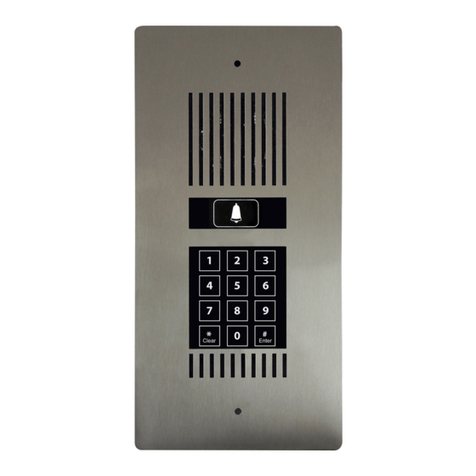
Our Model DP5 Flush Mount Door Phone is specifically designed for
connection to a National Communications DOOR STATION CONTROLLER.
DP5 is available in Vertival (DP5-V) and Horizontal (DP5-H) orientation.
They can be FLUSH MOUNTED or SURFACE MOUNTED if the optional
SMK3-V or SMK3-H Surface Mount Unit is used.
IfyourDP5isexposedtoRain,thenyoushouldusetheoptionalTransparent
Perspex Door Phone Cover DPC3-V or DPC3-H. See page 8.
If your DP5 is exposed to Very High Rainfall, or is located adjacent to the
beach, then you should use the optional Transparent Perspex Extreme
Weather Door Phone Cover XWC3-V or XWC3-H. See page 14.
When a visitor presses the Touch Sensitive BELL symbol of DP5, it will
command the Door Station controller to ring all telephones on the telephone
line. The user can then communicate with the visitor by answering any
ringing telephone.
DP5 also incorporates a Touch Sensitive Numeric Keypad that will allow a
visitor to enter a specific 4 to 6 digit code, which will cause an electric gate
or door to open. See pages 5-7.
DP5 incorporates 2 internal Relays which can be used to independently
control 2 separate electric doors or gates.
DP5 has a 316 Marine Grade Stainless Steel fascia plate, which has been
coated with a tough transparent protective polymer material.
DP5 can operate at distances of up to 300 meters from the Controller,
providing high quality cabling such as CAT5 is used.
Up to two Door Phones (Models DP1 to DP5) can be connected to the
same telephone line. See your reseller for details. This allows for a Door
Phone to be located at two different locations.
DP5 is supplied with a TWO YEAR FACTORY WARRANTY.

National Communications Page 3
OPERATION
DOOR PHONE CALL
To initiate a Door Phone call
1. Touch the BELL on the Door Phone.
2. You will hear a RING TONE until the call is answered.
3. Once answered, you will be able to communicate.
PEDESTRIAN LOCK
To open Lock 1 or Lock 2
A Visitor :
1. Enter a 4 , 5 or 6 digit User Access Code
2. Press Enter Note : the # key is also labelled Enter.
3. If an incorrect entry is made, press CLEAR
and then enter a correct Access Code
Note : the * key is also labelled Clear.

Page 4 National Communications
DOOR PHONE PERFORMANCE
DP5 is IDEAL for RESIDENTIAL USE or COMMERCIAL USE, where
ROADNOISEisNOTHIGH.
It is not designed for INDUSTRIAL USE where ambient noise can be
constantly high.
The volume of the audio communication on the internal phones should
be comfortably audible (a similar level to a telephone call) providing :
•The person at the Door Phone is talking directly towards the Door
Phone and at a distance of no more than 1 to 2 feet away (max 500-600
mm).
•TheDoorPhoneismountedataheightofabout1.5meters(5feet).You
canmountatalowerlevel to allowforvery young children,butvolume will
suffer.
•No plates or other material are placed over the front face of the Door
phone.OurDoorPhoneCoveraccessory,SurfaceMountKitora properly
designedRainHoodwillnotaffectperformance.
The volume of the audio communication at the Door Phone should be
comfortably audible, providing :
•There is not excessive road noise or other noise near the Door Phone.
This will affect the automatic gain circuit used in this device.
•ThathighqualityADSLFILTERINGisfittedaheadoftheDSCONTROLLER
where ADSL is used on the same line. If you do not do so, volume in both
directionswillbeaffected.RefertoyourDoorStationControllerUserGuide
for detailed information on the use of ADSL with this product.

National Communications Page 5
USER CODE PROGRAMMING
Up to 99 separate User Codes can be entered.
User codes can be 4, 5 or 6 digits in length.
User codes can also be deleted.
An Owner Code is used to set up and delete User Codes.
The Default Owner code is : 999999
The Owner Code can be changed on request to any 4, 5 or 6 digit number
by the Dealer or Installer.
Allowable Codes : Any 4 to 6 digit number
except 0000,00000, 000000
Default Code is : 999999
Important Note : The Owner Code CANNOT be 0000, 00000 or 000000
If the Owner Code is changed, please record the NEW Owner Code
here :
------ ------ ------ ------ ------ ------
SINGLE LOCK OR GATE
If you are only using a single Lock or Gate, refer to page 6 for User
Code Programming instructions.
DUAL LOCK OR GATE
If you are using Two separate Locks or Gates, refer to page 7 for User
Code Programming instructions.

Page 6 National Communications
USER CODE PROGRAMMING
SINGLE LOCK OR GATE USE
TO ENTER OR DELETE A USER CODE
1. PRESS ### on the DP5 keypad. (you will hear 2 beeps)
2. ENTER your 4-6 digit Owner Code, followed by #
(you will hear 2 beeps)
A. TO ENTER A NEW USER CODE
i) Press #1 (you will hear 2 beeps)
ii) Enter the New User Number (01 - 99) (you will hear 2 beeps)
iii) Enter the New User Code (4-6 digits)
iv) Press # (you will hear 2 beeps)
OR
B. TO DELETE AN EXISTING USER CODE
i) Press #1 (you will hear 2 beeps)
ii) Enter the User Number (01 - 99) (you will hear 2 beeps)
iii) Enter 0000# (you will hear 2 beeps)
Note : User Codes cannot be changed, they must be
deleted first and then re-entered.

National Communications Page 7
USER CODE PROGRAMMING
DUAL LOCK OR GATE USE
TO ENTER OR DELETE A USER CODE
1. PRESS ### on the DP5 keypad. (you will hear 2 beeps)
2. ENTER your 4-6 digit Owner Code, followed by #
(you will hear 2 beeps)
A. TO ENTER A NEW USER CODE
i) Press #1 (you will hear 2 beeps)
ii) Enter the New User Number (01 - 99) (you will hear 2 beeps)
iii) Enter the New User Code (4-6 digits)
iv) Press # (you will hear 2 beeps)
v) Then Press :
Press 2# to access Zone 2 only (you will hear 2 beeps)
or
Press 3# to access Zones 1 and 2 (you will hear 2 beeps)
B. TO DELETE AN EXISTING USER CODE
i) Press #1 (you will hear 2 beeps)
ii) Enter the User Number (01 - 99) (you will hear 2 beeps)
iii) Enter 0000# (you will hear 2 beeps)
Note : User Codes cannot be changed, they must be
deleted first and then re-entered.

Page 8 NationalCommunications
RAIN PROTECTION
DP5’s are not WATER PROOF
DP5 is designed to be highly WEATHER RESISTANT and will prove
reliable over long periods of time, providing it is not exposed to direct
rain.
DP5’s Touch Switch technology eliminates the possibility of water
entering via the trigger switch or keypad.
DP5’s speaker is made of a plastic mylar material and great effort has
been taken to maximise weather proofing all electronic components.
IfDP5isexposedtodirectrain,westronglyrecommendthatyouuseour
optional DPC3 Door Phone Cover, or the SMK3 Surface Mounting Kit
which has a rain deflector, to minimise the chance of water permeating
intotheDP5unitandcausingunreliabilityorpremature failure.Bothare
available for use with DP5’s mounted Vertically or Horizontally.
If DP5 will be exposed to very high levels of rain (or sea spray if near the
ocean),thenyoushoulduseourExtremeWeatherCoverXWC3.Seepage
14forfurtherdetails.
Door Phone Cover
For Flush Mounted DP5
Order Code is : DPC3-V
Order Code is : DPC3-H
Made from strong 5mm
transparent perspex
Surface Mount Kit
For Surface Mounted DP5
Order Code is : SMK3-V
Order Code is : SMK3-H
Made from 304 Grade
Stainless Steel
Flush Mounting Surface Mounting

National Communications Page 9
MOUNTING THE DOOR PHONE
DP5 should be mounted at the average face height of
1.5 metres (5 feet) for optimum performance.
The main body of the DP5 unit is designed
to be recessed into a wall surface.
It can also be surface mounted if the
optional SMK3-V or SMK3-H kit is used.
To speed up Flush Mount installations, a
WMB3 ‘Wall Mount box’ is supplied with
your DP5.
The galvanised iron WMB3 is designed to
be recessed into a wall cavity.
DP5 is then screwed onto the WMB3,
using 2 supplied stainless steel mounting
screws.
When using the WMB3, you must allow for a recessed area
of : H 255mm, W 95mm, D 40mm
or : H 95mm, W 255mm, D 40mm

Page10 NationalCommunications
BALANCE POT ADJUSTMENT
Your DOOR PHONE is preset at the factory for maximum performance. Our
sophisticated circuitry is designed to measure the background noise present
at your site and then apply maximum gain.
In most cases you SHOULD NOT NEEDTO MAKEANYADJUSTMENTS.
If you are using Two Door Phones, it is possible that you will need to adjust
the POT of one or both Door Phones to suit your specific site conditions.
The balance POT is provided in case you experience one of the following :
• Audio is distorted.
• Audio (speech) can only be heard in 1 direction.
Should you encounter one of these problems, you will need to make slow
careful adjustments in one direction or the other until speech can be heard
in both directions and without distortion.
The balance POT is located on the back of DOOR PHONE under a small
removable white plastic plug. It should be adjusted using a small flat blade
screwdriver.
IMPORTANT NOTES
1) You will require TWO PEOPLE to adjust your Door Phone.
2) Wait 10 seconds after answering before adjusting the Pot.
3) DO NOT USEA TELEPHONE IN CLOSE PROXIMITY TO THE DOOR
PHONE, as feedback interference will affect the Balance Pot settings.
4)TheBalancePOT does not increase volume. Moving it when unnecessary
may cause a deterioration in audio quality or a loss of audio in 1 direction.

National Communications Page 11
BALANCE POT ADJUSTMENT
TRIMPOT ADJUSTMENT
Balance Pot
is located here
under a white
plastic sealing
cap.
Adjust the POT a small amount in 1 direction and test audio
communication quality.
If the quality is improving, carry out a further small adjustment in the
same direction and re-test.
If quality is becoming worse, please adjust the POT in the other direction
and continue with small adjustments until the best communication
quality is achieved.
Clockwise adjustments will improveAudio at the DP5 Door Phone.
Anti-Clockwise adjustments will improve Audio to the internal
Telephones.

Page 12 +
LED BRIGHTNESS
POT ADJUSTMENT
Adjustment Pot
is located here
under a white
plastic sealing
cap.
The brightness of the WHITE and BLUE lights (LED’s) that illuminate
the front panel of the DP5 can be adjusted to suit.
This is done by adjusting a Micro Pot, which is located under a white
plastic sealing cap (see diagram above). There are 3 separate Micro
Pots and White sealing caps on DP5. You should use the Pot located
under the Top-Left white sealing cap. You will need to use a small flat
blade or start blade screwdriver to make the adjustment.
To REDUCE the brightness, turn the Pot CLOCKWISE
To INCREASE the brightness, turn the Pot ANTI-CLOCKWISE

NationalCommunications Page 13
KEYPAD BEEP VOLUME
POT ADJUSTMENT
Adjustment Pot
is located here
under a white
plastic sealing
cap.
The LOUDNESS of the NUMERIC KEYPAD BEEP on the front panel of
the DP5 can be adjusted to suit.
This is done by adjusting a Micro Pot, which is located under a white
plastic sealing cap (see diagram above). There are 3 separate Micro
Pots and White sealing caps on DP5. You should use the Pot located
under the Top-Right white sealing cap. You will need to use a small flat
blade or start blade screwdriver to make the adjustment.
To INCREASE the BEEP VOLUME, turn the Pot CLOCKWISE
To REDUCE the BEEP VOLUME, turn ANTI-CLOCKWISE

Page14 NationalCommunications
EXTREME WEATHER COVER
Wherevera DP5 DoorPhoneis exposed toExtremeWeather Conditions such
as : * Located in the open in areas where there is High Rainfall with Wind
* When loacted very close to the ocean
Itis HIGHLYrecommendedthatyouuseourExtremeWeatherCover.
ThiscoverismadefromStrong 5mmTransparentPerspex.
This cover has a Hinged Front Face which should be lifted when the Door
Phone is to be used and returned to its closed position when the Door Phone
call or Gate Access use is complete.
TheHingeDoor can be rotated beyong 180 degrees, allowingittobe open up
to and leaning against a wall or post. It should then be returned to its normal
position when DP5 use is complete.
The Extreme Weather Cover can also
be used with our SMK3 Surface
Mounting Kit, allowing for DP5 to be
mountedonto a wall surface or pole.
The Extreme Weather Cover is only
available in Vertical Orientation at this
time(XWC3-V).

National Communications Page 15
NOTES

SPECIFICATIONS
Vertical Dimensions (mm) : 264 (H) x 130 (W) x 34 (D)
Horizontal Dimensions (mm) : 130 (H) x 264 (W) x 34 (D)
Weight : 500g
Communications Connector : Phoenix 4 pin
Lock 1 Connector : Phoenix 2 pin
Lock 2 Connector : Phoenix 2 pin
ACMA COMPLIANT : Supplier Number N 782
WARRANTY
This device is guaranteed against defects from workmanship for a period
of two years (24 months) from the date of purchase. In the event of
failure, you should return the product, along with proof of purchase date,
and a written statement about the nature of the problem.
This Warranty shall not apply to any unit which has been subject to
alteration, modification, abuse, negligence, accident, external voltage/
lightning surge or used in any manner contrary to these instructions.
The obligation is solely to repair or replace the product. The warrantor
is not liable for any incidental or consequential damages due to such
defects.
The user is responsible for freight costs to the repair point. The warrantor
will be responsible for freight costs in returning this unit back to the
user.
Damage caused to this device or attached equipment, by lightning strikes
or over voltage surge is not covered under this warranty.
CASE SEALED AT FACTORY
OPENING THE CASE VOIDS THE WARRANTY
Page16 NationalCommunications
Other manuals for DP5
1
Table of contents
Other NatComm Intercom System manuals

NatComm
NatComm DP2 User manual

NatComm
NatComm DP4 User manual

NatComm
NatComm DP5 User manual

NatComm
NatComm DP2 User manual

NatComm
NatComm DS3 User manual

NatComm
NatComm DP2 User manual

NatComm
NatComm DS1 User manual

NatComm
NatComm DP4 User manual

NatComm
NatComm DS6 User manual

NatComm
NatComm DP1 User manual