National Comfort Products NCC Series User manual

NCC Series
Cased Coil
Installation
Guide
Please read the Manual prior to starting the installation.
All phases of this installation must comply with National, State and Local codes.
HEATING & A/C EQUIPMENT
NATIONAL
COMFORT
PRODUCTS
®
Thru-the-Wa Comfort for a types of Multi-Family Construction
National Comfort Products
A Division of National Refrigeration and Air Conditioning Products, Inc.
539 Dunksferry Road • Bensalem, PA 19020-5908
(800) 523-7138 • Fax (215) 639-1674
www.nationalcomfortproducts.com
HEATING & A/C EQUIPMENT
NATIONAL
COMFORT
PRODUCTS
®
Go Thru-the-Wa

Table of Contents
Safety Warnings ................................................................. page 3
Inspection ........................................................................... page 3
Installation Preparation........................................................ page 3
Condensate Drain Preparation............................................ page 3
Coil Installation ................................................................... page 4
Metering Device/TXV .......................................................... page 6
Leak Check.......................................................................... page 7
Important: This Document is customer property and is to remain with this unit.
DO NOT DESTROY OR THROW AWAY THIS MANUAL.
IT SHOULD BE KEPT IN A SAFE PLACE FOR FUTURE REFERENCE.

3
NCC Series Cased Coil Installation Instructions
POTENTIAL SAFETY HAZARDS ARE ALERTED USING
THE FOLLOWING SYMBOLS. THE SYMBOL IS USED
IN CONJUNCTION WITH TERMS THAT INDICATE THE
INTENSITY OF THE HAZARD.
!WARNING
THIS SYMBOL INDICATES A POTENTIALLY HAZARDOUS
SITUATION, WHICH IF NOT AVOIDED, COULD RESULT
IN SERIOUS INJURY, PROPERTY DAMAGE, PRODUCT
DAMAGE OR DEATH.
!WARNING
THIS SYMBOL INDICATES A POTENTIALLY HAZARDOUS
SITUATION, WHICH IF NOT AVOIDED, MAY RESULT IN
MODERATE INJURY OR PROPERTY DAMAGE.
!CAUTION
!WARNING
PRODUCT DESIGNED AND MANUFACTURED TO
PERMIT INSTALLATION IN ACCORDANCE WITH
LOCAL AND NATIONAL BUILDING CODES. IT IS THE
INSTALLER’S RESPONSIBILITY TO ENSURE THAT
PRODUCT IS INSTALLED IN STRICT COMPLIANCE WITH
THE AFOREMENTIONED CODES. MANUFACTURER
ASSUMES NO RESPONSIBILITY FOR DAMAGE
(PERSONAL, PRODUCT OR PROPERTY) CAUSED DUE
TO INSTALLATIONS VIOLATING REGULATIONS.
!WARNING
CERTIFIED TECHNICIANS OR THOSE INDIVIDUALS
MEETING THE REQUIREMENTS SPECIFIED BY NATE MAY
USE THIS INFORMATION. PROPERTY AND PRODUCT
DAMAGE OR PERSONAL INJURY HAZARD MAY OCCUR
WITHOUT SUCH BACKGROUND.
ALL POWER SOURCES SHOULD BE DISCONNECTED
PRIOR TO SERVICING. FAILURE TO DO SO MAY CAUSE
PERSONAL INJURY OR PROPERTY DAMAGE.
!WARNING
Safety Warnings! Inspection
On receiving the product, visually inspect it for any major
shipping related damages. Shipping damages are the carrier’s
responsibility. Inspect the product labels to verify the model
number and options are in accordance with your order.
Manufacturer will not accept damage claims for incorrectly
shipped product.
Installation Preparation
Read all the instructions in this guideline carefully while paying
special attention to the WARNING and CAUTION alerts. If any
of the instructions are unclear, clarify with a certified technician
before proceeding. Gather all tools needed for successful
installation of the unit prior to beginning the installation. Note
that absence of pressure/charge does not verify a leak. Check
coils for leaks prior to installation.
Condensate Drain Preparation
National Comfort Products recommends an auxiliary drain pan be
provided and installed by the installing contractor, which should
be properly sloped, installed according to code, and terminated
in an area visible to the home owner. The auxiliary pans provide
extra protection to the area under the unit should the primary and
secondary drain plug up and overflow.
AS EXPRESSED IN OUR PRODUCT WARRANTY;
NATIONAL COMFORT PRODUCTS WILL NOT BE BILLED
FOR ANY STRUCTURAL DAMAGES CAUSE BY FAILURE
TO FOLLOW THIS INSTALLATION REQUIREMENT.
!WARNING
DRAIN LINES FROM THE AUXILIARY DRAIN PAN SHOULD
NOT BE CONNECTED TO THE PRIMARY DRAIN LINE OF
THE COIL.
!CAUTION
DO NOT INSTALL COILS WITH PLASTIC DRAIN PANS ON
ANY OIL OR DRUM TYPE FURNACES OR APPLICATIONS
WHERE TEMPERATURE OF THE DRAIN PAN MIGHT
EXCEED 260±5 ºF. A METAL PAN SHOULD BE INSTALLED
IN THESE APPLICATIONS.
!WARNING

4
Install coils with the drain pan and/or casing on a flat, level
surface. Slope the coil 1/4” towards the drain. Condensate lines
must be installed in accordance with building codes. It is the
contractor’s responsibility to ensure proper condensate drainage
at the time of the installation; National Comfort Products bears
no responsibility for damages caused by improper condensate
management.
SOME COILS HAVE PRIMARY AND SECONDARY
DRAIN PORTS ON BOTH SIDES OF THE PAN TO OFFER
INSTALLATION FLEXIBILITY, SO ENSURE ALL THREADED
PLUGS ARE IN PRESENT AND TIGHTENED IN ANY
UNUSED DRAIN PORTS. THESE MAY BE HIDDEN BEHIND
THE COIL CASING ACCESS DOOR. FAILURE TO DO SO
MAY RESULT IN PROPERTY WATER DAMAGE; IT IS THE
CONTRACTOR’S RESPONSIBILITY TO ENSURE THESE
PLUGS ARE PRESENT AND TIGHT.
!CAUTION
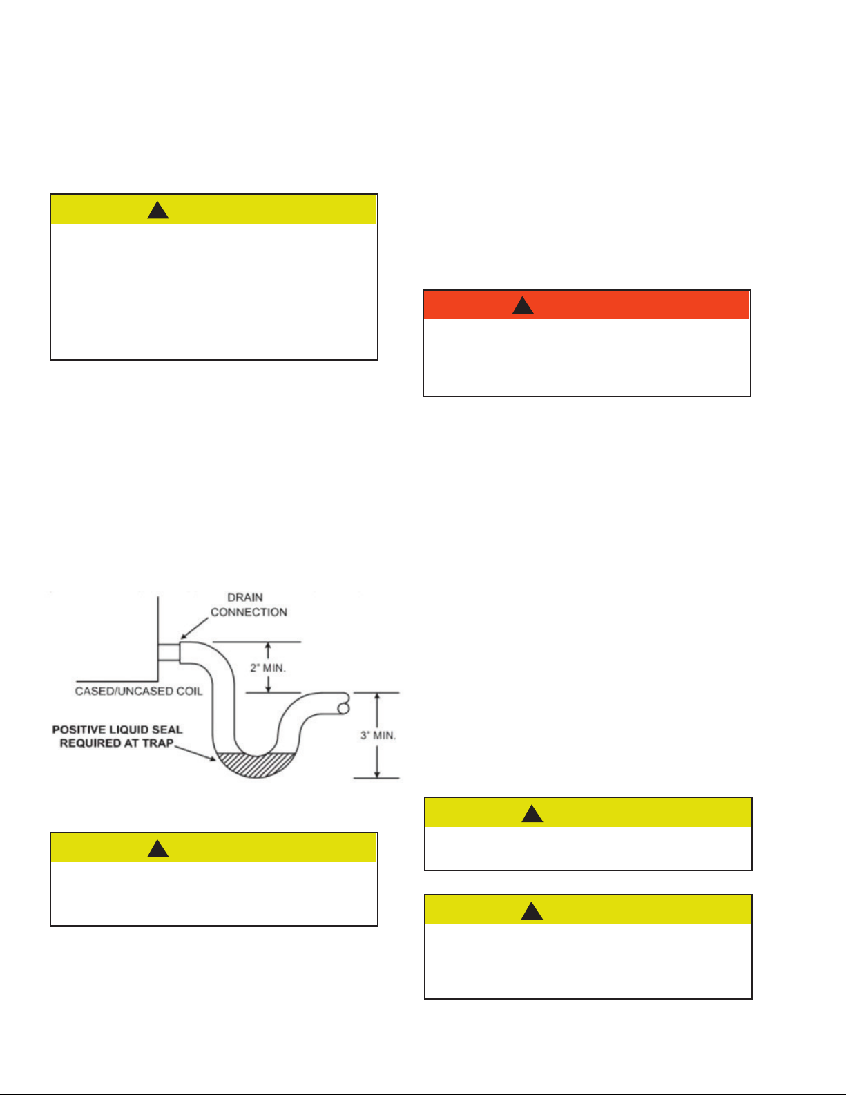
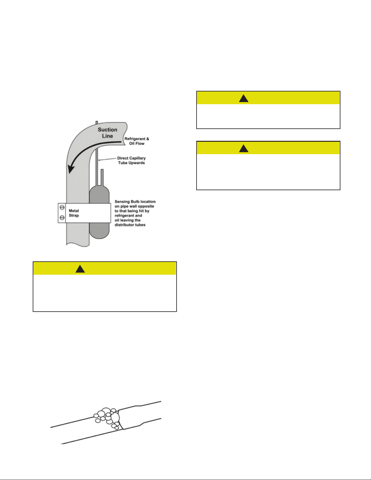
The drain lines must be installed with ¼” per foot pitch to provide
free drainage. A condensate trap MUST be installed on the
primary drain line to ensure proper drainage of the condensate.
The trap must be installed in the drain line below the bottom of
the drain pan. Fig. 1 illustrates the typical drain trap installation.
Prior to installation, ensure drain pan hole is not obstructed.
Additionally, National Comfort Products recommends the drain
lines be insulated to prevent sweating and dripping.
Fig. 1
USE TEFLON TAPE TO CONNECT THE DRAIN LINES TO
THE THREADS IN THE DRAIN PAN. DO NOT USE SOLVENT
BASED PIPE DOPE. THIS WILL REDUCE THE LIFE OF THE
PAN.
!CAUTION
The drain pan has primary (white) and secondary (red) drain
connections. If a secondary drain line is required, it should be
run separately from the primary and should terminate in a highly
visible location. Condensate disposal through the secondary
drain line indicates that the primary drain line is plugged and
needs cleaning. If a secondary drain line will not be provided,
plug the secondary drain. Drain plugs are NOT to be reused
without plumbers tape or putty. Drain line connection should be
finger tightened, then turned no more than one complete turn
as needed to ensure a firm connection. DO NOT overtighten
connection or damage may occur.
Coil Installation
THE COIL IS MANUFACTURED WITH DRY NITROGEN
PRE-CHARGE. RELEASE THE PRESSURE THROUGH THE
SCHRADER VALVE TEST PORT PRIOR TO INSTALLATION.
IF HOLDING PRESSURE IS NOT PRESENT, RETURN COIL
TO DISTRIBUTOR FOR EXCHANGE.
!WARNING
Clean coil fins with degreasing agent or mild detergent and rinse
fins clean prior to installation. Refer to page 7 for coil cleaning/
maintenance guidance.
The refrigerant line sizes should be selected according to the
recommendations of the outdoor unit manufacturer.
Care must be taken to ensure all connection joints are burr-free
and clean. Failure to do so may increase chances of a leak. It is
recommended to use a pipe cutter to remove the spun closed
end of the suction line.
To reduce air leakage, rubber grommets may be present where
the lines pass through the coil case. To avoid damage, remove
grommets prior to brazing by sliding over the lines. Use a
quenching cloth or allow the lines to cool before reinstalling the
grommets.
Use of wet rags/quenching cloth is highly recommended to
prevent weld-related damages to the casing and Schrader valve
(if present).
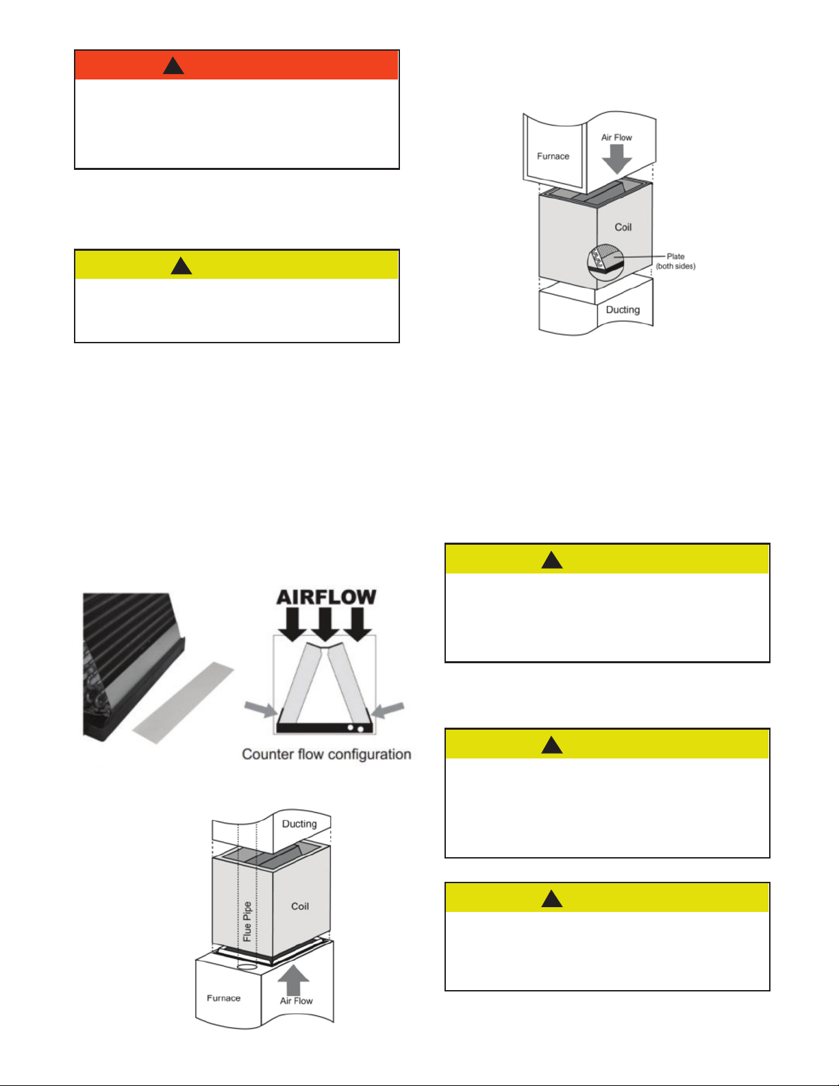
Can be installed in either an upflow or a downflow application.
COIL SHOULD BE INSTALLED ON THE DISCHARGE SIDE
OF THE FURNACE
!CAUTION
NATIONAL COMFORT PRODUCTS COILS MAY INCLUDE
A SCHRADER VALVE ON THE SUCTION MANIFOLD.
ENSURE THAT THE SCHRADER VALVE AND VALVE
CORE (WHERE PRESENT) ARE PROTECTED FROM HEAT
TO PREVENT LEAKAGE.
!CAUTION

5
AS MENTIONED ELSEWHERE IN THIS DOCUMENT, IN
AN APPLICATION INVOLVING OIL FURNACE A METAL
DRAIN PAN MUST BE USED. COILS INSTALLED ON AN
OIL FURNACE MUST HAVE A MINIMUM OF SIX INCHES
CLEARANCE BETWEEN THE TOP OF THE FURNACE AND
BOTTOM OF THE DRAIN PAN.
!WARNING
Vertical Upow/Downow Installation
WHEN INSTALLING IN CONJUNCTION WITH A GAS
FURNACE IN A VERTICAL ORIENTATION, ENSURE THAT
THERE IS 2” GAP BETWEEN THE BOTTOM OF THE DRAIN
PAN AND THE OUTLET OF THE FURNACE.!
!CAUTION
To set up coils for downflow application, install the two 3” wide
by 16” long galvanized metal plates on the outside of the coil,
against the fins on each side of the coil as shown in Fig. 5A-3.
These plates are supplied with the coil.
Do NOT exceed 350 cfm/ton of airflow for downflow
applications.
Fig. 2A
Metal Plate location for a Downow/Counterow
Application
Fig. 2B
Upow Application
Fig. 2C
Downow Application
To position the coil on furnace:
1. Locate the air outlet of the furnace.
2. Adjust flanges accordingly and position the coil over or under
the furnace outlet.
3. Place ductwork over the casing.
Refer to Furnace/Air Handler manufacturer literature for specific
coil installation guidelines and recommendations
DUE TO HIGHER DESIGNED RADIANT HEAT, A SIX
INCH SPACER (PLACED BETWEEN THE FURNACE EXIT
AND THE INLET OF THE EVAPORATOR) SHOULD BE
INSTALLED WHEN MATCHING UP A NATIONAL COMFORT
PRODUCTS COIL WITH AN ULTRALOW NOX (ULN)
FURNACE.
!CAUTION
Suction Line Connection
THE SENSING BULB AND TXV BODY MUST BE
PROTECTED FROM OVERHEATING DURING BRAZING.
THE SENSING BULB AND TXV BODY MUST BE COVERED
USING A QUENCH CLOTH OR WET CLOTH WHEN
BRAZING. POINTING THE BRAZING FLAME AWAY FROM
THE VALVE AND SENSING BULB PROVIDE PARTIAL
PROTECTION ONLY.
!CAUTION
SOME NATIONAL COMFORT PRODUCTS COILS MAY
INCLUDE A SCHRADER VALVE ON THE SUCTION
MANIFOLD. ENSURE THAT THE SCHRADER VALVE AND
VALVE CORE (WHERE PRESENT) ARE PROTECTED
FROM HEAT TO PREVENT LEAKAGE.
!CAUTION

6
1. Ensure suction line connection joints are burr-free and clean.
Failure to do so may increase chances of a leak and introduce
contaminants to the system. It is recommended to use a pipe
cutter to remove the spun closed end of the suction line.
2. Swedge (or use a field supplied coupler) and braze the field
supplied refrigerant suction line tubing to the coil stub using
approved industry practices.
DO NOT ATTEMPT TO TOUCH BRAZED JOINTS WHILE
HOT. SEVERE BURNS MAY RESULT.
!WARNING
Metering Device/TXV
National Comfort Products coils are made with a TXV.
Fig. 3A
Components of a typical TXV assembly
THE SENSING BULB AND TXV BODY MUST BE
PROTECTED FROM OVERHEATING DURING BRAZING.
THE SENSING BULB AND TXV BODY MUST BE COVERED
USING A QUENCH CLOTH OR WET CLOTH WHEN
BRAZING. POINTING THE BRAZING FLAME AWAY FROM
THE VALVE AND SENSING BULB PROVIDE PARTIAL
PROTECTION ONLY.
!WARNING
TXV Bulb Horizontal Mounting
The orientation and location of the TXV bulb has a major
influence on the system performance.
ENSURE THAT THE TXV BULB IS IN DIRECT CONTACT
WITH THE SUCTION/VAPOR LINE. GAP BETWEEN THE
BULB AND TUBE SHOULD BE AVOIDED. FAILURE TO DO
SO WILL IMPAIR THE PROPER FUNCTIONING OF THE
TXV VALVE.
!CAUTION
It is recommended that the TXV bulb be installed parallel to the
ground (on a horizontal plane). The bulb position should be
at 2 o’clock or 10 o’clock. Fig. 7B-2 shows the recommended
position for the TXV bulb installation in the horizontal plane.
Fig. 3B-1
Recommended location for horizontal TXV bulb
mount
The TXV sensing bulb SHOULD be mounted on the suction line
approximately 6” from the TXV or coil housing using the metal
clamp provided. In order to obtain a good temperature reading
and correct superheat control, the TXV sensing bulb must
conform to ALL of the following criteria:
1. The sensing bulb MUST be in direct and continuous contact
with the suction line.
2. The sensing bulb should be mounted horizontally on the
suction line.
3. The sensing bulb MUST be mounted at the 2 o’clock or 10
o’clock position on the circumference of the suction line.
4. The sensing bulb MUST be insulated from outside air.
A properly mounted sensing bulb will prevent false readings
caused by liquid refrigerant that may have formed inside the
suction/vapor line. Insulation will protect the sensing bulb from
false readings due to contact with warm air.
Please refer to the installation guide of the outside unit for
specific bulb mounting requirements.

7
As recommended in Section 3B-1, the TXV sensing bulb should
be mounted in a horizontal plane in relation to the suction/vapor
line. However, some installation configurations may require that
the sensing bulb be mounted vertically. In this instance, place
the bulb opposite the piping wall being hit by refrigerant and oil
leaving the distributor tubes, and with capillary tubes directed
upwards as shown in Fig. 3B-2.
TXV Bulb Vertical Mounting
Fig. 3B-2
Recommended location for vertical TXV bulb mount
IF THE TXV SENSING BULB IS MOUNTED VERTICALLY;
THE CAPILLARY MUST BE DIRECTED UPWARDS. THE
BULB MUST BE MOUNTED ON THE WALL OPPOSITE TO
THAT BEING DIRECTLY HIT BY THE REFRIGERANT AND
OIL LEAVING THE DISTRIBUTOR TUBES.
!CAUTION
1. Following outdoor unit manufacturer instructions and
recommendations, charge the system with dry nitrogen to a
maximum pressure of 150 PSIG.
2. Check all brazed and screw on line connections by applying a
soap solution to the joint. A leak will produce bubbles in the
soap solution.
Leak Check
3. If any leaks or are discovered, relieve system pressure and
repair leaks. Repeat steps 1-3.
4. With no leaks or weak connections present, evacuate the
system and charge as per the outdoor unit manufacturer
instructions and specifications.
System Charging
AN IMPROPERLY CHARGED SYSTEM WILL LIKELY
CAUSE LOSS IN SYSTEM PERFORMANCE AND MAY
DAMAGE THE COMPRESSOR.
!CAUTION
REFER TO OUTDOOR UNIT MANUFACTURER CHARGING
GUIDELINES AND RECOMMENDATIONS. THE
RECOMMENDATIONS GIVEN BELOW ARE GENERAL IN
NATURE AND ARE NOT TO SUPERSEDE OUTDOOR UNIT
MANUFACTURER SPECIFICATIONS.
!CAUTION
Add refrigerant until the subcooling measured at the indoor
unit liquid line matches the subcooling recommendation of the
outdoor manufacturer.
Coil Cleaning Instructions
National Comfort Products cased coils are equipped with a two-
piece panel door to allow for cleaning and maintenance access.
Remove one or both doors to access the coil for cleaning.
For both copper and aluminum tube coils, it is recommended
to flush with the coil with water. There are coil cleaners that
are available that contain corrosive chemicals, such as, but not
limited to, chlorine and hydroxide, that are not approved for use
on National Comfort Products copper and aluminum

National Comfort Products
539 Dunksferry Road • Bensalem, PA 19020-5908
(800) 523-7138
Fax (215) 639-1674
HEATING & A/C EQUIPMENT
NATIONAL
COMFORT
PRODUCTS
®
12/2022
Table of contents
Other National Comfort Products Indoor Furnishing manuals
Popular Indoor Furnishing manuals by other brands

Unique Furniture
Unique Furniture Nors Chair 708-157-1042 Assembly instruction

Core Products
Core Products Corona Grey CRG914 Instruction leaflet

physa
physa FR-6 user manual

Article
Article LUMVIG Assembly instructions

Multistore
Multistore Compact Series Assembly instructions

Aprimatic
Aprimatic WI-MATIC ATC300E MET Fitting instructions