National Flooring Equipment PANTHER 8274 User manual

#8274 & #9274 PANTHER®
PLANETARY GRINDERS
INSTRUCTION MANUAL
Read Manual Before Operating Machine
#8274 #9274
9250 XYLON AVENUE NORTH • MINNEAPOLIS, MN 55445 • U.S.A.
800-245-0267 • 763-535-8206 • FAX 763-535-8255 • FAX 800-648-7124
WEB SITE: www.nationalequipment.com • E-MAIL: [email protected]
National
Flooring Equipment, Inc.

Page 2
8274/9274 TABLE OF CONTENTS
Table of Contents..........................................................................................................2
Rules for Safe Operation ..........................................................................................3-7
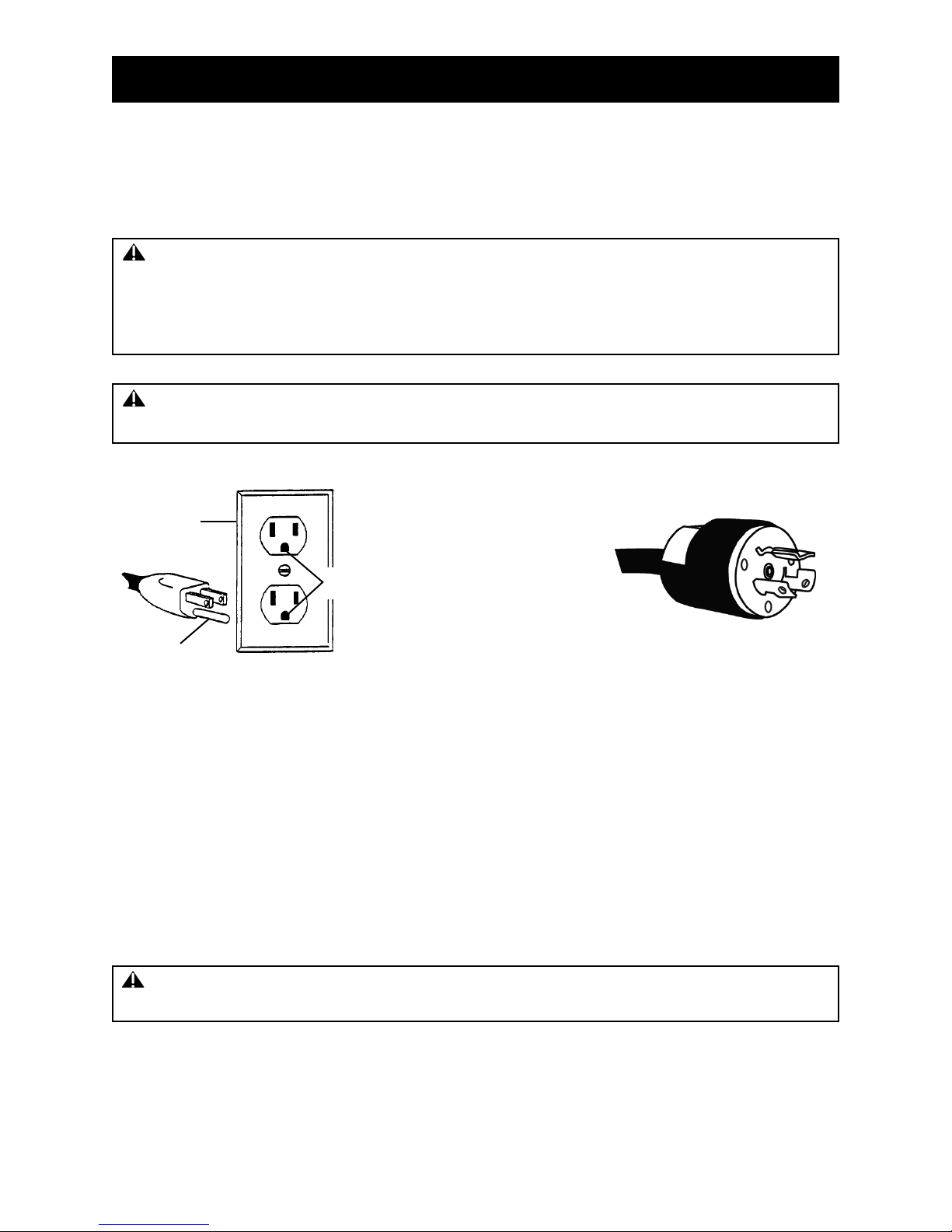
A. Grounding ......................................................................................................6
B. Extension Cords ............................................................................................7
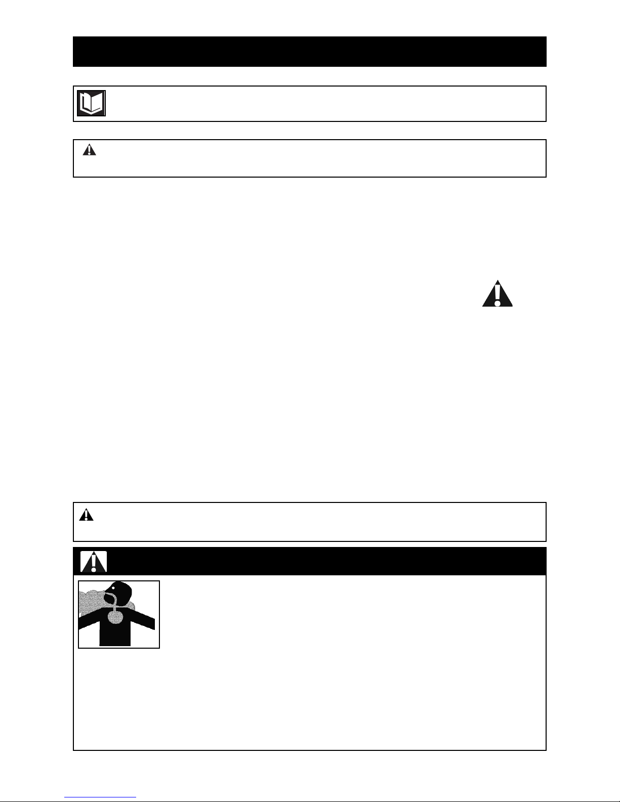
Safety Instructions ........................................................................................................8
Transportation ..............................................................................................................9
A. Load and Unloading........................................................................................9
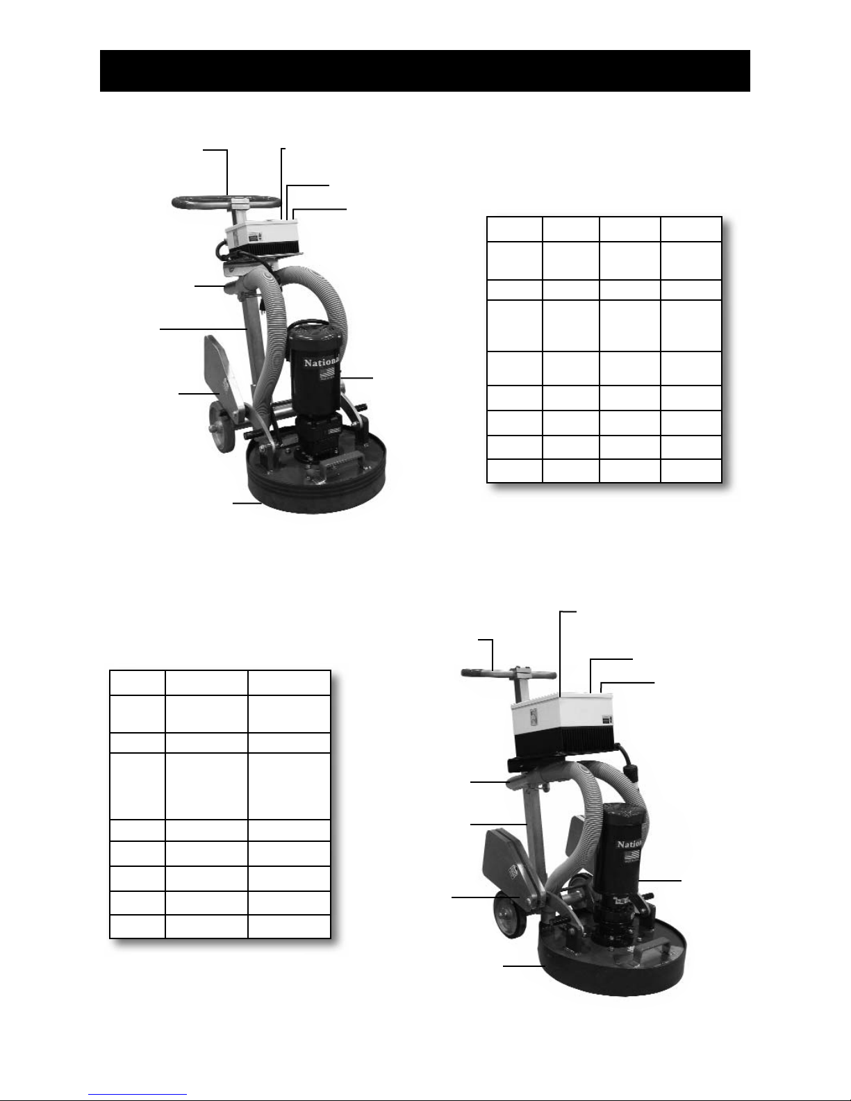
Features/Specifications ..............................................................................................10
Procedure ..............................................................................................................11-23
A. Handle Assembly ..........................................................................................11
B. Vacuum Port ................................................................................................12
C. Weights ........................................................................................................12
D. Rubber Dust Guard ......................................................................................13
E. Belt ..........................................................................................................14-16
F. Idler Bearing Replacement ..........................................................................17
G. Pulley Replacement......................................................................................17
H. Satellite Shaft Replacement ........................................................................18
I. Satellite Bearing Replacement ....................................................................18
J. Removing Top Gear Plate ............................................................................19
K. Light In Cord Plug ........................................................................................19
L. Machine Start Up ..........................................................................................20
M. Controller Fault/Circuit Overload .................................................................21
N. Controller Codes ..........................................................................................22
i. Controller Default Codes........................................................................22
ii. Controller Error Codes ..........................................................................22
O. Troubleshooting..........................................................................................22.1
P. Power Cord ..................................................................................................23
Q. Power Source Voltage ..................................................................................23
Accessory Set-Up ..................................................................................................24-25
Maintenance ..........................................................................................................26-27
A. Maintaining Tools ..........................................................................................26
B. Cleaning........................................................................................................27
C. Repairs..........................................................................................................27
Complete Parts List ..............................................................................................28-31
A. 8274 ........................................................................................................28-29
B. 9274 ........................................................................................................30-31
Part Numbers & Diagrams ....................................................................................32-36
Labels ........................................................................................................................37
Magnetic Tooling....................................................................................................38-40
Traditional Tooling..................................................................................................41-43
Tooling Packages ..................................................................................................44-46
Guarantee ..................................................................................................................46
Return Sheet ..............................................................................................................47

Page 3
RULES FOR SAFE OPERATION
READ AND SAVE ALL INSTRUCTIONS FOR FUTURE USE. Before use, be sure everyone operating this
equipment reads and understands this manual as well as any labels packaged with or attached to
the tool.
1. KNOW YOUR EQUIPMENT: Read this manual carefully to learn equipment applications and
limitations as well as potential hazards associated with this type of equipment.
2. GROUND YOUR TOOL: See Grounding.
3. AVOID DANGEROUS ENVIRONMENTS: Do not use in rain, damp or wet locations, or in the
presence of explosive atmospheres (gaseous fumes, dust or flammable materials). Remove materials
or debris that may be ignited by sparks.
4. KEEP WORK AREA CLEAN AND WELL LIT: Cluttered, dark work areas invite accidents.
5. DO NOT USE ON STEPS:
6. DRESS PROPERLY: Do not wear loose clothing. These may be caught in moving parts. When
working outdoors, wear rubber gloves and insulated non-skid footwear. Keep hands and gloves away
from moving parts.
7. USE SAFETY EQUIPMENT: Everyone in the work area should wear safety goggles or glasses
complying with current safety standards. Wear hearing protection during extended use and a dust
mask for dusty operations. Hard hats, face shields, safety shoes, etc. should be worn when specified
or necessary.
8. KEEP BYSTANDERS AWAY: Children and bystanders should be kept at a safe distance from the
work area to avoid distracting the operator and contacting the tool or extension cord. Operator should
be aware of who is around them and their proximity.
9. PROTECT OTHERS IN THE WORK AREA: Provide barriers or shields as needed to protect others
from debris.
10. USE PROPER ACCESSORIES: Using accessories that are not recommended may be hazardous.
Be sure accessories are properly installed and maintained. Do not delete a guard or other safety
device when installing an accessory or attachment.
11. CHECK FOR DAMAGED PARTS: Inspect guards and other parts before use. Check for
misalignment, binding of moving parts, improper mounting, broken parts and any other conditions that
may affect operation. If abnormal noise or vibration occurs, turn the tool off immediately and have the
problem corrected before further use. Do not use damaged equipment. Tag damaged tools “DO NOT
USE” until repaired. A guard or other damaged parts should be properly repaired or replaced. For all
repairs, insist on only identical National replacement parts.
12. REMOVE ALL ADJUSTING KEYS AND WRENCHES: Make a habit of checking that the adjusting
keys, wrenches, etc. are removed from the tool before turning it on.
13. GUARD AGAINST ELECTRIC SHOCK: Prevent body contact with grounded surfaces such as pipes,
radiators, ranges and refrigerators. When making cuts, always check the work area for hidden wires
or pipes. Hold your tool by insulated nonmetal grasping surfaces. Use a Ground Fault Circuit
Interrupter (GFCI) to reduce shock hazards.
14. AVOID ACCIDENTAL STARTING: Be sure equipment is turned off before plugging it in. Do not use a
tool if the power switch does not turn the tool on and off.
15. DO NOT FORCE EQUIPMENT: Equipment will perform best at the rate for which it was designed.
Excessive force only causes operator fatigue, increased wear and reduced control.
16. KEEP HANDS AWAY FROM ALL CUTTING EDGES AND MOVING PARTS.
17. WEAR GLOVES WHEN CHANGING ACCESSORIES.

Page 4
RULES FOR SAFE OPERATION
18. DO NOT ABUSE CORD: Never unplug by yanking the cord from the outlet. Pull plug rather than cord
to reduce the risk of damage. Keep the cord away from heat, oil, sharp objects, cutting edges and
moving parts.
19. DO NOT OVERREACH. MAINTAIN CONTROL: Keep proper footing and balance at all times.
Maintain a firm grip.
20. STAY ALERT: Watch what you are doing, and use common sense. Do not use when you are tired,
distracted or under the influence of drugs, alcohol or any medication causing decreased control.
21. STARTING MACHINE: On/off switch must be in off position before connecting to power source.
22. UNPLUG EQUIPMENT: When it is not in use, unplug tool before changing accessories or performing
recommended maintenance.
23. MAINTAIN EQUIPMENT CAREFULLY: Keep handles dry, clean and free from oil and grease. Keep
cutting edges sharp and clean. Follow instructions for lubricating and changing accessories.
Periodically inspect tool cords and extension cords for damage. Have damaged parts repaired
or replaced.
24. STORE IDLE EQUIPMENT: When not in use, store in a dry, secured place. Keep away
from children.
25. MAINTAIN LABELS AND NAMEPLATES: These carry important information. If unreadable or
missing, contact National for a free replacement.
26. MACHINE IS HEAVY, DO NOT DROP.
27. WHEN OPERATING MACHINE, TETHER CORD MUST BE CONNECTED TO OPERATOR.
28. DO NOT ALLOW the rotating plates to come into contact with the supply cord.
29. Regularly examine the supply cord for damage, such as cracking or aging. If damage is found,
replace the cord before further use. Only replace the supply cord with the type specified in the
instruction manual.
WARNING: Exposure to dust may cause respiratory ailments. Use approved NIOSH or OSHA
respirators, safety glasses or face shields, gloves and protective clothing. Provide adequate ventilation
to eliminate dust, or to maintain dust level below the Threshold Limit Value for nuisance dust as
classified by OSHA.

Page 5
RULES FOR SAFE OPERATION
CHARACTERISTICS OF A DEFENSIVE OPERATOR
• Education
• Alert
• Skills
• Judgment
• Common Sense
• Recognizes the Hazards
• Understands the Defense
• Acts Correctly
A GOOD OPERATOR IS A “DEFENSIVE” OPERATOR
QUALITIES
Education: Learns about the machine and the environment.
Alert: Stays alert at all timesnever lets guard down.
Skills: Only performs duties he/she are qualified to do. Always tries to improve.
Judgment: Plays it safe. Doesn’t take chances.
Common Sense: Does the right thing without having to be told. Applies knowledge.
Recognizes the Hazards: Maintains alertness. Anticipates danger.
Understands the Defense: Knows that safety isn’t an accidentit’s a thinking person’s choice.
Acts Correctly: Does not cave in to peer pressure. Performs correctly when supervised or not.

Page 6
RULES FOR SAFE OPERATION
GROUNDED TOOLS: TOOLS WITH THREE PRONG PLUGS
Tools marked “Grounding Required” have a three wire cord and three prong grounding plug. The plug
must be connected to a properly grounded outlet (Figure A & B).If the tool should electrically malfunction
or break down, grounding provides a low resistance path to carry electricity away from the user, reducing
the risk of electric shock.
The grounding prong in the plug is connected through the green wire inside the cord to the grounding
system in the tool. The green wire in the cord must be the only wire connected to the tool's grounding
system and must never be attached to an electrically “live” terminal.
Your tool must be plugged into an appropriate outlet, properly installed and grounded in accordance with
all codes and ordinances. The plug and outlet should look like those in Figure A & B.
Figure A
2
1
3
GROUNDING
Figure B
WARNING: Electrical cords can be hazardous. Misuse can result in fire or death by electrical
shock. Read carefully and follow all directions.
WARNING: Improperly connecting the grounding wire can result in the risk of electric shock.
Check with a qualified electrician if you are in doubt as to whether the outlet is properly grounded. Do
not modify the plug provided with the tool. Never remove the grounding prong from the plug. Do not
use the tool if the cord or plug is damaged. If the plug will not fit the outlet, have a proper outlet
installed by a qualified electrician.
115 Volt 230 Volt
1. Cover of grounded outlet box
2. Outlet ground
3. Grounding prong
WARNING: Only use the socket outlet on the machine for purpose specified in the instruction
manual.
Jobsite receptacles can vary. Check voltage at receptacles on the jobsite for the best voltage supply. 15
amp GFI outlets are not recommended.

Page 7
RULES FOR SAFE OPERATION
EXTENSION CORDS
Grounded tools require a three wire extension cord. Double insulated tools can use either a two or three
wire extension cord. As the distance from the supply outlet increases, you must use a heavier gauge
extension cord. Using extension cords with inadequately sized wire causes a serious drop in voltage,
resulting in loss of power and possible tool damage.
The smaller the gauge number of the wire, the greater the capacity of the cord. For example, a 10 gauge
cord can carry a higher current than a 12 gauge cord. When using more than one extension cord to make
up the total length, be sure each cord contains at least the minimum wire size required. If you are using
one extension cord for more than one tool, add the nameplate ampere and use the sum to determine the
required minimum wire size.
GUIDELINES FOR USING EXTENSION CORDS
• If you are using an extension cord outdoors, make sure it is marked with the suffix “W-A” (“W” in
Canada) to indicate that it is acceptable for outdoor use.
• Be sure your extension cord is properly wired and in good electrical condition. Always replace a
damaged extension cord or have it repaired by a qualified person before using it.
• Protect your extension cords from sharp objects, excessive heat and damp or wet areas.
• Keep away from water. Do not use if wet.
• Inspect thoroughly before each use. DO NOT USE IF DAMAGED.
• Make sure equipment is not running before disconnecting cord.
• FULLY INSERT plug into outlet.
• Do not remove, bend or modify any metal prongs or pins of cord.
• Do not use excessive force to make connections.
• Do not connect a three prong plug to a two-hole cord.
• Avoid overheating. Uncoil cord and do not cover it with any material.
• Do not walk on cord.
• Do not drive, drag or place objects over cord.
• Minimum 12 gauge cord, 50ft maximum length.
• Regularly examine the supply cord for damage, such as cracking or aging. If damage is found, replace
the cord before further use.
• Only replace the supply cord with the type specified in the instruction manual.
READ AND SAVE ALL INSTRUCTIONS FOR FUTURE REFERENCE.
WARNING: Electrical cords can be hazardous. Misuse can result in fire or death by electrical
shock. Read carefully and follow all directions.
WARNING: Do not allow the rotating plates to come into contact with the supply cord.

Page 8
8274/9274 SAFETY INSTRUCTIONS
• Only qualified, trained personnel should operate this unit.
• Loose or damaged parts should be replaced immediately. Failure to do so could cause equipment
damage or serious injury.
• Switches and levers should be inspected. Do not use if defective.
• Power control box, motor and switches should be completely enclosed at all times with no
exposed wiring.
• Disconnect power from unit before servicing. Failure to do so can cause electrical shock.
• Only use National components. Failure to do so could cause damage or serious injury.
• Always be aware of support personnel and their proximity when in operation. Block off work area.
• Support personnel should never stand next to machine, in front of or behind machine while machine is
running. Failure to do so could cause serious bodily injury or death.
• Manual should be kept with machine in supplied holder for access by operator at all times.
• Always wear eye protection when running machine.
• Never defeat switches or guards.
• Remove blade when machine is not in use and/or lower cutting head to floor. Failure to do so could
cause serious bodily injury.
• Wear gloves when changing blades. Always shut machine off when changing blades.
WARNING: Know and understand before operation. Failure to do so could cause damage to
equipment or bodily injury.
Read and understand operators instruction manual and instructional video
before operating this equipment.
WARNING: Failure to follow any of the above instructions could cause damage to machine,
damage to property or serious bodily injury or death.
WARNING: SILICA DUST WARNING
Grinding/cutting/drilling of masonry, concrete, metal and other materials can
generate dust, mists and fumes containing chemicals known to cause serious fatal
injury or illness, such as respiratory disease, cancer, birth defects or other
reproductive harm. If you are unfamiliar with the risks associated with the particular
material being cut, review the material safety data sheet and/or consult your
employer, the material manufacturer/supplier, governmental agencies such as
OSHA and NIOSH and other sources of hazardous materials. California and some other other
authorities, for instance, have published lists of substances known to cause cancer, reproductive
toxicity, or other harmful effects. Control dust, mist and fumes at the source where possible. In this
regard use good work practices and follow the recommendations of the manufacturer/supplier,
OSHA/NIOSH, and occupational and trade associations. When the hazards from inhalation of dust,
mists and fumes cannot be eliminated, the operator and any bystanders should always wear a
respirator approved by OSHA/MSHA for the material being cut.

Page 9
LOAD AND UNLOAD
• Always disconnect from power source before transporting.
• Loosen Handle Securing Bolts to slide handle down to make machine easier to load. Retighten Bolts
when handle is at the desired height.
8274/9274 TRANSPORTATION

Page 10
8274/9274 FEATURES/SPECIFICATIONS
Digital Read-Out
-Able to monitor load or RPM’s
Variable Speed
Forward & Reverse
Adjustable
Handle
Angle
Vac Port
Adjustable
Handle
Height
Adjustable
Weights
(double adjustable
weights on 8273-3,
8274-4)
115 Volt
18″ Disc
Adjustable
Dust Guard
Adjustable
Handle
Height
Adjustable
Dust Guard
22″ Disc
Double
Adjustable
Weights
Vac Port
Adjustable
Handle
Angle
230 Volt
8274 18″GRINDER
9274 22″GRINDER
Digital Read-Out
-Able to monitor
load or RPM’s
Variable Speed
Forward
& Reverse
Stock # 8274-1 8274-3 8274-4
Disc
Size 18 Inch 18 Inch 18 Inch
HP 1½ 3 4
Motor
Phase
3 Phase
*
3 Phase Single
Phase
Voltage 115 V 230 V 115 V
Height 38″ 38″ 38″
Length 32″ 32″ 32″
Width 19″ 19″ 19″
Weight 265 lbs. 360 lbs. 360 lbs.
Stock # 9274-1 9274-2
Disc
Size 22 Inch 22 Inch
HP 3 4
Motor
Phase 3 Phase* Single
Phase
Voltage 230 V 115 V
Height 38″ 38″
Length 32″ 32″
Width 23″ 23″
Weight 430 lbs. 380 lbs.
* Power Conversion from
Single Phase to 3 Phase
* Power Conversion from
Single Phase to 3 Phase

Page 11
HANDLE ASSEMBLY
Handle adjusts to operator height. Loosen handle bolt and adjust handle (Figure A) to desired length and
properly tighten bolt. Handle adjusts in both height and angle. Adjust handle grip to desired angle and
firmly secure (Figure B). Adjust handle to desired angle and secure with clip (Figure C).
8274/9274 PROCEDURE
WARNING: Handle must be engaged with both securing bolts. Failure to do so could cause
serious injury.
Figure B
Figure A
Figure C

Page 12
VACUUM PORT
8274/9274 PROCEDURE
Figure A
WARNING: Make sure you are using the proper style of vacuum for what you are grinding,
scraping or sanding. Failure to do so could cause emissions of hazardous particulates or explosion
due to fine dust (ie, wood sanding), which is flammable. Make sure the system you are using complies
or exceeds OSHA recommended standard. Make sure the rubber dust guard is covering all the way to
the floor surface.
The machine is provided with a vacuum port at the rear of
the machine. Use a vacuum hose that snugly fits either on
the outside or the inside of the port.
Connect vacuum hoses (Figure A).
Figure B
WEIGHTS
Weights rotate front to back. To apply added weight to head, one or or both weights can be rotated
forward (Figure B). To take load off machine, pull weights to the back (Figure C). If load is over 100%,
pull weights back. If circuit breakers blow, pull weights back.
Figure C

Page 13Page 13
8274/9274 PROCEDURE
RUBBER DUST GUARD
ATTACHING
Return machine to upright position. Attach dust guard (Figure A) keeping as close to the floor as
possible. If dust is exposed when operating machine, stop machine and readjust dust guard.
POSITIONING
Unplug machine from power source. With machine sitting in the operating position, remove rubber dust
guard held on by Velcro. Starting at one end of the shroud, place guard to rest on floor surface. Firmly
press rubber guard into securing Velcro on shroud. Wrap rubber guard all the way around the shroud
making sure the guard rests on the floor surface and is secure. Inspect for air gaps.
If rubber guard securing Velcro becomes loaded up with debris, wash out with mild soap or blow out with
an air hose. If Velcro on the machine is damaged or worn out, replace before using the machine. If the
rubber guard is cut, damaged or worn out, replace before using the machine. Safety glasses need to be
worn by operator and all people working around the equipment.
WARNING: NEVER operate machine without rubber guard in place covering plate completely.
Failure to do so could cause serious injury.
NEVER mount or readjust rubber guard with machine plugged in. Disconnect from power source
before mounting or readjusting the rubber guard.
Figure A

Page 14
8274/9274 PROCEDURE
BELT
BEFORE ANY MAINTENANCE, MAKE SURE MACHINE IS DISCONNECTED FROM POWER
SOURCE
TO ACCESS BELT
•Remove the dust guard (page 13)
•Remove the four bolts on top of the shroud cover (Figure A)
•Pull back on the handle. The shroud should lift up and away from the grinding disc (Figure B). If it
does not lift away, using a pry bar on each side, gently pry plate away from shroud - Do Not Force
•Move machine back and off the plate (Figure C)
Figure A
Figure B
Figure C

Page 15
8274/9274 PROCEDURE
BELT (CONTINUED)
BELT TENSION
NOTE: IF THE TENSION IN NOT PROPERLY TIGHTENED, THE TOOLING WILL SLIP AND NOT PERFORM
AS DESIGNED
8274
•Loosen (do not remove) two of the three tension bracket bolts (Figure A)
•Pivot the loosened bracket so it is evenly spaced with the center pulley (Figure B & C)
•Apply pressure with a pry bar between the gear plate and tension bracket (Figure D), tighten both bolts
•Recheck the spacing between the brackets and the center pulley (Figure B & C)
•Belt should be tightened to have less than ¼” of movement (Figure E)
9274
•Loosen (do not remove) both bolts on one of the tension brackets (Figure F)
•Pivot the loosened bracket so it is evenly spaced with the center pulley (Figure G & H)
•Apply pressure with a pry bar between the gear plate and tension bracket (Figure I), tighten both bolts on
the bracket
•Recheck the spacing between the brackets and the center pulley (Figure G & H)
•Belt should be tightened to have less than ¼” of movement (Figure J)
Figure A Figure B Figure C Figure D Figure E
Figure F
Figure G Figure H
Figure I
Figure J
Brackets
Center Pulley
Brackets
Pry Bar
Brackets
Center Pulley
Brackets

Page 16
8274/9274 PROCEDURE
BELT (CONTINUED)
REMOVING BELT (8274 & 9274)
•Loosen bolt or bolts on one of the tension brackets (Figure A & B)
•Push in on tension bracket toward gear plate
•Belt should be loose enough to slide off
REPLACING BELT (8274 & 9274)
•Loop belt around in pattern shown (Figure C & D)
•Follow Belt Tension procedure
MOUNTING PLATE ON TO MACHINE
•Grease shaft first
•Shaft key needs to line up with key notch on plate (Figure E). To temporarily hold key in place,
secure key with an o-ring or rubber band (Figure F)
•Position machine over plate (Figure G)
•Swivel machine until key fits into plate
•Secure the four bolts on top of the shroud cover (Figure H)
•Replace the dust guard
Figure E Figure F
Figure G
Figure H
Figure B
Figure A Figure C Figure D
Center Pulley
8274 9274
Brackets
Key Notch O-Ring

Page 17
IDLER BEARING REPLACEMENT
•Remove belt, following belt removal instructions (page 14-16)
•Remove snap ring (Figure A)
•Remove idler bearings (Figure B)
•Replace bearing
•Replace snap ring, making sure ring is seated in the groove (Figure C)
•Reinstall belt
PULLEY REPLACEMENT
•Remove belt, following belt removal instructions (page 14-16)
•Remove nut from top of pulley (Figure D)
•Slide pulley up and off. Key will fall out (Figure E)
•Replace key in new pulley
•Line up key in pulley (Figure F)
•Install pulley
•Reinsert nut
•Reinstall belt
8274/9274 PROCEDURE
Figure A Figure B Figure C
Figure D Figure E Figure F

Page 18
SATELLITE SHAFT REPLACEMENT
•Remove pulley following pulley replacement instructions (page 17)
•Push down on shaft (Figure A)
•Lift up on plate and pull out shaft (Figure B)
•Replace shaft (Figure C)
•Replace Pulley (page 17)
•Replace nut
•Reinstall belt
SATELLITE BEARING REPLACEMENT
•Remove pulley (page 17)
•Remove satellite shaft
•Block up plate (Figure D)
•Knock out bearing (Figure E)
•Turn plate over on blocks
•With the retainer ring turned upwards,
replace the bearing (Figure F)
keeping the bearing as straight as
possible (Figure G)
NOTE: BEARING CAN BE DIFFICULT TO GET INSERTED
•Replace shaft
•Replace pulley (page 17)
•Replace nut
•Reinstall belt
8274/9274 PROCEDURE
Figure A Figure B Figure C
Figure E
Figure D
Figure G
Figure F

Page 19
REMOVING TOP GEAR PLATE
•Remove belt, following belt removal instructions (page 14-16)
•With a 4 millimeter allen wrench, remove the four gear plate cover screws (Figure A)
•Remove gear plate (Figure B)
•Remove both snap rings (Figure C)
•Remove gear (Figure D)
•Block up gear (Figure E)
•Knock out bearings (Figure F)
•Reinstall bearings one at a time
NOTE: HITTING AROUND THE OUTSIDE PERIMETER OF THE BEARING,
KEEP THE BEARING AS STRAIGHT AS POSSIBLE
•Replace gear back onto plate keeping fingers clear (Figure G)
(PINCH POINT), wiggle bearing until it drops down. DO NOT FORCE.
•Reinsert snap rings making sure they are seated in the groove
•Reinsert gear plate
•Reinsert four screws
•Reinstall belt
8274/9274 PROCEDURE
LIGHT IN CORD PLUG
Red flashing light in cord plug is normal (Figure H).
The red (LED) shows the pulses to the motor
Figure C
Figure D
Figure B
Figure A
Figure F
Figure G
Figure E
Figure H

Page 20
8274/9274 PROCEDURE
Start: Press Start Button
Stop: Press Stop Button
Change Direction: Press Fwd/Rev Button then Enter
Button
Change Speed: Up Arrow = Faster,
Down Arrow = Slower
ONCE POWER IS APPLIED TO DRIVE (This will usually mean the unit is plugged in) the display will appear
similar to this: STOP> XX.XX HZ
NORMALLY THE FREQUENCY IS PRE-SET TO 50 OR 60 HZ. The exception: last operating speed is
displayed in HZ
PRESS START - Motor will start to turn. Full speed will be achieved in 20 seconds.
If motor is running wrong direction - Press FWD/REV button on keypad. Then press “enter” button
within 3 seconds
TO CHANGE SPEED - Press the up arrow to increase speed (up to a factory preset maximum). Press Down
Arrow button to decrease speed
PRESS STOP - to stop running motor
MACHINE START UP PROCEDURE
TO RUN MACHINE
1. Connect machine to power source.
2. Attach tether cord to both operator and machine
(Figure A). Failure to do so could cause damage to
property and/or machine.
3. Securely hold handle with one hand.
Note: Applying light pressure downward on the handle
takes pressure off the head of the machine.
4. Turn switch to “on” position (Figure B).
Note: Machine is programmed with a slow start.
BLUE LIGHTS: ENABLE, READY TO RUN
RED LIGHTS: DEFAULT (SEE TROUBLESHOOTING, ERROR CODES)
Enter
Fwd/Rev
Start
Stop
Down Arrow
(Decreases Speed)
Up Arrow
(Increases Speed)
Figure A
tether cord
attached
NOTE: Once machine is running, keep it on “load mode”. Always be aware that the load does not go
over 100%.
This manual suits for next models
1
Table of contents
Other National Flooring Equipment Grinder manuals

National Flooring Equipment
National Flooring Equipment GP700 User manual

National Flooring Equipment
National Flooring Equipment 8274-4 User manual

National Flooring Equipment
National Flooring Equipment HELIX User manual

National Flooring Equipment
National Flooring Equipment HELIX User manual

National Flooring Equipment
National Flooring Equipment GP3000 User manual