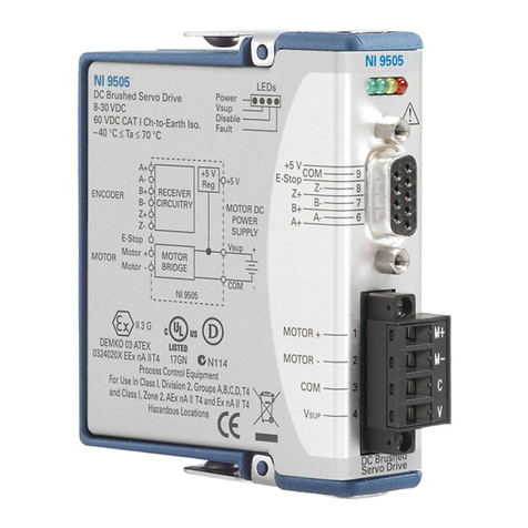
National Instruments NI 9505E User manual

OPERATING INSTRUCTIONS AND SPECIFICATIONS
NI 9505E
DC Brushed Servo Drive

NI 9505E Operating Instructions and Specifications 2ni.com
This document describes how to use the National
Instruments 9505E module and includes dimensions, pin
assignments, and specifications for the NI 9505E DC brushed
servo drive. Visit ni.com/info and enter rdsoftwareversion
to determine which software you need for the modules you are
using. For information about installing, configuring, and
programming the system, refer to the system documentation. Visit
ni.com/info and enter cseriesdoc for information about
C Series documentation.
Caution National Instruments makes no electromagnetic
compatibility (EMC) or CE marking compliance claims
for the NI 9505E. The end-product supplier is responsible
for conformity to any and all compliance requirements.
Caution The NI 9505E must be installed inside a suitable
enclosure prior to use. Hazardous voltages may be
present.

© National Instruments Corp. 3 NI 9505E Operating Instructions and Specifications
NI 9505E Dimensions
The following figure shows the dimensions of the NI 9505E.
Figure 1. NI 9505E Dimensions in Millimeters (Inches)
73.4 (2.89)
0.0 (0.00)
0.0 (0.00)
26.7 (1.05)
58.4 (2.30)
66.0 (2.60)

NI 9505E Operating Instructions and Specifications 4ni.com
NI 9505E Hardware Overview
The NI 9505E provides unique flexibility and customization. The
NI 9505E works together with the LabVIEW FPGA Module to
create a highly customizable motor drive or actuator amplifier.
Figure 2 illustrates the functionality of the NI 9505E working in
conjunction with the LabVIEW FPGA Module in a typical motion
control application. Figures 3 and 4 show more detailed versions
of the position, velocity, and current loops implemented in the
LabVIEW FPGA Module. A typical application contains a
position loop, velocity loop, and current loop, implemented in
the LabVIEW FPGA Module block diagram. Depending on the
application, you may not need to use all three loops. The examples
installed in the labview\examples\CompactRIO\
Module Specific\NI 9505 directory illustrate methods for
implementing each of these loops.
The NI 9505E returns the motor or actuator current data to the
LabVIEW FPGA Module for use in a current loop or for
monitoring. The NI 9505E also returns status information such as
drive fault status, VSUP presence, and emergency stop status to the
LabVIEW FPGA Module for use in system monitoring. Refer
to the NI 9505 Reference Help book in the LabVIEW Help,

© National Instruments Corp. 5 NI 9505E Operating Instructions and Specifications
available by selecting Help»Search the LabVIEW Help, for
more information about the available status information.
The LabVIEW FPGA Module generates a PWM signal and sends
the signal to the NI 9505E. The PWM signal is proportional to the
desired current or torque you want to provide to the motor or
actuator. Increasing the PWM duty cycle results in increased
current and thus increased torque.
Quadrature encoder signals pass through the NI 9505E and are
processed in the LabVIEW FPGA Module for use in the position
and velocity loops. Refer to Figure 5 for a typical NI 9505E
connection example, including encoder and E-Stop inputs.
For more advanced motion control applications, NI SoftMotion
provides functions for trajectory generation, spline interpolation,
position and velocity PID control, and encoder implementation
using both the LabVIEW Real-Time Module and the LabVIEW
FPGA Module. With NI SoftMotion you can create a custom
motion controller without the need to develop the trajectory
generator or spline engine yourself. Refer to the labview\
examples\CompactRIO\Module Specific\NI 9505 directory
for example VIs using the NI 9505E and NI SoftMotion.

NI 9505E Operating Instructions and Specifications 6ni.com
Figure 2. NI 9505E Block Diagram
Position
Loop
Velocity
Loop
Current
Loop
Fault
Monitor
Bridge
Controller
Fault
Detection
H-Bridge
Current
Sense
Encoder
Feedback
DC
Servo
Motor
Velocity
Command
Current
Command*
Position
Setpoint
LabVIEW FPGA Module NI 9505E
Motor
(PWM)
Encoder
Feedback
Position
Decoder
Current
Feedback
Velocity
Feedback
Position
Feedback
Velocity
Estimator
* Proportional to Torque

© National Instruments Corp. 7 NI 9505E Operating Instructions and Specifications
Figure 3. LabVIEW FPGA Module NI 9505E PID Loop
Position
Setpoint
Position Error
Velocity
Acceleration
Vff
Kp
Ki
Kd
Kv
Current Command
(Proportional to Torque)
Position
Decoder
LabVIEW FPGA Module
Encoder
Feedback
Aff
Position
Feedback

NI 9505E Operating Instructions and Specifications 8ni.com
Figure 4. LabVIEW FPGA Module NI 9505E Current Loop
Hot-Swap Behavior
The NI 9505E is always disabled when it is inserted in the chassis,
regardless of whether VSUP is present or not. You can enable the
drive using the Enable Drive method in software. Refer to the
NI 9505 Reference Help book in the LabVIEW Help, available
by selecting Help»Search the LabVIEW Help,for more
information about enabling the drive.
When the NI 9505E is removed from the chassis while it is
enabled, the power to the motor is removed and the motor
decelerates to a stop based on its own friction.
Current Error
Motor
(PWM)
Kp
Ki
Current
Limiter
Current
Command
(Proportional
to Torque)
Current Feedback
(from NI 9505E)
Current Limit
LabVIEW FPGA Module

© National Instruments Corp. 9 NI 9505E Operating Instructions and Specifications
LED Indicators
The NI 9505E has four LEDs to display status information.
Power
The Power LED (green) illuminates when the NI 9505E is properly
inserted into a powered chassis.
Note The Power LED does not illuminate when the
chassis is in sleep mode.
1 Power (green)
2V
SUP (Motor Power) (green)
3Disable (yellow)
4Fault (red)
1 2 3 4

NI 9505E Operating Instructions and Specifications 10 ni.com
VSUP
The VSUP LED (green) illuminates when the motor DC power
supply is properly connected and powering the drive.
Disable
The Disable LED (yellow) illuminates when the drive is disabled.
The drive is disabled by default at power-on. You can enable the
drive using the Enable Drive method in software. Refer to the
NI 9505 Reference Help book in the LabVIEW Help, available
by selecting Help»Search the LabVIEW Help, for more
information about this method.
Fault
Caution If the Fault LED is lit, determine the cause of the
fault and correct it before enabling the drive.
The Fault LED (red) illuminates when a fault occurs. A fault
disables the drive. Causes for fault are the following:
Caution VSUP greater than 40 V will result in damage to
the NI 9505E.
•Overvoltage
• Undervoltage

© National Instruments Corp. 11 NI 9505E Operating Instructions and Specifications
• Motor terminal (MOTOR±) short to VSUP
• Motor terminal (MOTOR±) short to COM
• Module temperature exceeds 115 ºC
• Sending commands to the motor before enabling the drive
Note Do not command motor movement until the drive
is enabled with the Enable Drive method. Attempting to
control the motor before it is enabled will result in a fault.
• Violating PWM minimum pulse width requirements. Refer to
the Specifications section for more information about PWM.
Sleep Mode
This module supports a low-power sleep mode. Support for sleep
mode at the system level depends on the chassis that the module is
plugged into. Refer to the chassis manual for information about
support for sleep mode. If the chassis supports sleep mode, refer
to the software help for information about enabling sleep mode.
Visit ni.com/info and enter cseriesdoc for information about
C Series documentation.
Typically, when a system is in sleep mode, you cannot
communicate with the modules. In sleep mode, the system
consumes minimal power and may dissipate less heat than it does

NI 9505E Operating Instructions and Specifications 12 ni.com
in normal mode. Refer to the Specifications section for more
information about power consumption and thermal dissipation.
Note The Power LED does not illuminate when the
chassis is in sleep mode.
Wiring the NI 9505E
The NI 9505E has a 9-pin female DSUB connector that provides
connections for the encoder inputs, a +5 V connection for encoder
power, a connection for an emergency stop input, and a connection
to COM. Refer to Table 1 for the pin assignments.
The NI 9505E also has a screw-terminal connector that provides
connections to a motor DC power supply and a DC brushed servo
motor. Connect the positive lead of the power supply to terminal 4,
VSUP, and the negative lead to terminal 3, COM. Refer to Table 2
for the terminal assignments.
Note You must use 2-wire ferrules to create a secure
connection when connecting more than one wire to a
single terminal on the NI 9505E screw-terminal.
Caution Do not turn on or plug in the motor DC power
supply until the screw-terminal connector is fully
inserted.

© National Instruments Corp. 13 NI 9505E Operating Instructions and Specifications
Table 1. NI 9505E DSUB Pin Assignments
Connector Pin Signal
1Encoder Phase A+
2Encoder Phase B+
3Encoder Index+ (Phase Z+)
4Emergency Stop (E-Stop)
5+5 V (output)
6Encoder Phase A–
7Encoder Phase B–
8Encoder Index– (Phase Z–)
9Common (COM)
Table 2. NI 9505E Screw-Terminal Terminal Assignments
Module Terminal Signal
M+ MOTOR+
M– MOTOR–
CCOM (motor DC power supply reference)
V VSUP (motor DC power supply)
9
8
7
6
5
4
3
2
1
M+
M–
C
V

NI 9505E Operating Instructions and Specifications 14 ni.com
Figure 5 shows a typical NI 9505E connection example, including
encoder and E-Stop inputs.
Figure 5. NI 9505E Connections
Motor
M+
M–
VSUP
COM
Motor DC
Power
Supply
NI 9505E
Shield
Shield
Phase A±
Phase B±
Index±
+5 V
COM
Shield
+24 V
E-Stop
Encoder
Feedback
COM

© National Instruments Corp. 15 NI 9505E Operating Instructions and Specifications
Optional Screw-Terminal Accessory
Use the NI 9931 Screw-Terminal Accessory instead of the
detachable screw-terminal connector to increase the output power
of the module at temperatures below 85 ºC. The NI 9931 is
available from ni.com (NI part number 780571-01) or by calling
your National Instruments sales representative. Refer to the
Specifications section for more information. Refer to Figure 6 for
an illustration.
Figure 6. NI 9505E Module with Optional Screw-Terminal Accessory
MOTOR +
MOTOR –
COM
V
sup

NI 9505E Operating Instructions and Specifications 16 ni.com
Motor Power Signals
The MOTOR+ and MOTOR– signals power the servo motor.
Motor direction is as follows:
•Forward—Clockwise (CW) facing motor shaft
•Reverse—Counterclockwise (CCW) facing motor shaft
Figure 7 shows clockwise and counterclockwise motor rotation.
Figure 7. Clockwise and Counterclockwise Motor Rotation
Tip If the motor does not turn in the desired direction,
reverse the MOTOR+ and MOTOR– signals.
CCW CW

© National Instruments Corp. 17 NI 9505E Operating Instructions and Specifications
Encoder Signals
The encoder signals consist of a Phase A, Phase B, and Index
(Phase Z) input. The NI 9505E supports differential and
single-ended inputs for Phase A, Phase B, and Index (Phase Z)
signals. Figures 8 and 9 show simplified schematic diagrams of the
encoder input circuit connected to differential and single-ended
inputs. You can also accommodate open-collector output encoders
by using a 1 kΩpull-up resistor on each line to +5 VDC. Refer to
the Specifications section for more information about the encoder
inputs.
The encoder signals are raw digital input signals. These signals are
used in the LabVIEW FPGA Module for position and/or velocity
feedback. Figures 2 and 3 illustrate the use of the encoder signals
in a position and velocity loop in the LabVIEW FPGA Module.
Refer to the examples installed at labview\examples\
CompactRIO\Module Specific\NI 9505 for examples of using
the encoder signals. Refer to the NI 9505 Reference Help book
in the LabVIEW Help, available by selecting Help»Search the
LabVIEW Help, for more information.

NI 9505E Operating Instructions and Specifications 18 ni.com
If the encoder cable length is greater than 3.05 m (10 ft), use
encoders with differential line driver outputs for your applications.
Power for a +5 V encoder—generated by a power supply on the
NI 9505E—is available on pin 5 of the DSUB connector.
Figure 8. Differential Encoder Input Circuit
Receiver
Phase +
Phase –
Encoder
COM
COM
+5 V
+5 V
Encoder NI 9505E

© National Instruments Corp. 19 NI 9505E Operating Instructions and Specifications
Figure 9. Single-Ended Encoder Input Circuit
Closed-loop servo applications require consistent directional
polarity between the motor and encoder for correct operation.
One industry-standard directional polarity is as follows:
• Positive = forward = clockwise (CW) facing motor shaft
• Negative = reverse = counterclockwise (CCW) facing motor
shaft
Refer to Figure 7 for a depiction of clockwise and
counterclockwise rotation. If encoder counting does not behave as
expected, change the encoder polarity in the FPGA or swap the
Phase A and Phase B connections.
Receiver
Encoder
Signal
Encoder
Encoder NI 9505E
No Connection
COM
COM
+5 V
+5 V
Table of contents
Other National Instruments Servo Drive manuals
National Instruments
National Instruments NI 9514 User manual

National Instruments
National Instruments NI 9505 User manual

National Instruments
National Instruments NI 9516 User manual

National Instruments
National Instruments NI 9505 User manual

National Instruments
National Instruments NI 9502 User manual

National Instruments
National Instruments AKD EtherCAT User manual

National Instruments
National Instruments NI 9516 User manual

National Instruments
National Instruments NI 9512 C Series User manual