National Instruments PS-15 User manual

INSTALLATION GUIDE
NI PS-14/15/16/17 Side Mount
Brackets
This document provides the installation procedure for the NI PS-14/15/16/17 Side Mount
Brackets. This accessory is used to mount NI PS-14/15/16/17 power supplies sideways to reduce
the installation depth.
Two side mounting options are possible:
• 35 mm DIN-Rail Mount
• Panel Mount
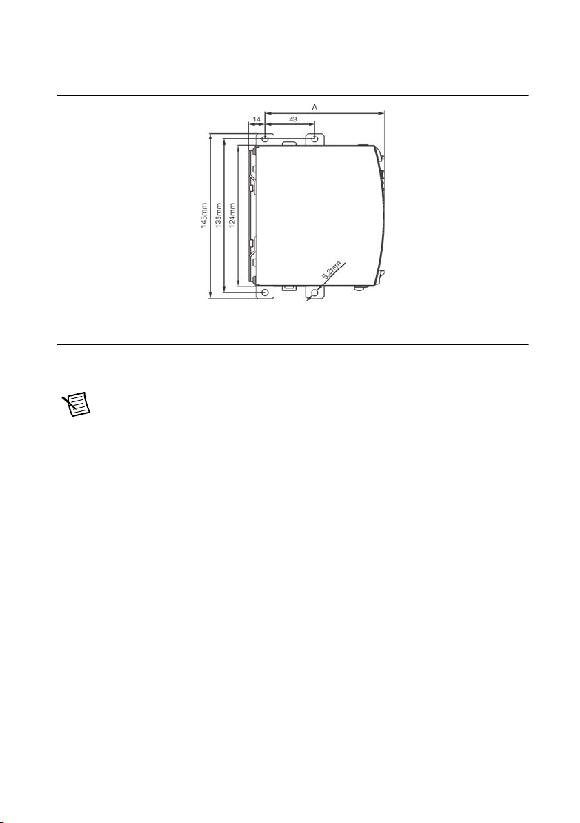
Bracket and Assembly Dimensions
This section provides bracket and assembly dimensions. Table 1 provides a summary of the
dimensions and weight of the overall assembly when a specific bracket set is mounted to a
specific power supply. The Unit column lists the available power supplies. The Bracket Set
column indicates the appropriate brackets to use with the specified power supply. The Acolumn
provides dimensions from the front of the power supply to the rearmost mounting screw for the
assembly of power supply and brackets. The Bcolumn provides the total installation depth of
the assembly when mounted. The Ccolumn provides the depth of the power supply only. The
Length column provides the total length of the assembly. The Width column provides the width
of the mounting brackets. The Height column provides the height of the brackets only. The
Bracket Set Weight column provides the weight of the bracket set only.
Table 1. Bracket Set and Assembly Dimensions and Weight
Units
Use
Bracket
Set A B*CLength Width Height
Bracket
Set
Weight
NI PS-14 199429-01 89 mm 38 mm 32 mm 145 mm 65 mm 37 mm 140 g
NI PS-15 199429-01 104 mm 38 mm 32 mm 145 mm 65 mm 37 mm 140 g
NI PS-16 199430-01 104 mm 66 mm 60 mm 145 mm 65 mm 63 mm 180 g
NI PS-17 199431-01 124 mm 88 mm 82 mm 145 mm 65 mm 84.5 mm 205 g
*If the unit is panel mounted, the B dimension shows the required installation depth. If the unit is DIN-Rail
mounted, the total installation depth is the B dimension plus 6 mm plus the height of the DIN-Rail.

2|ni.com |NI PS-14/15/16/17 Side Mount Brackets Installation Guide
Figure 1, Figure 2, and Figure 3 show the brackets for DIN-Rail mounting.
Figure 1 provides the layout of a mounting bracket in three physical dimensions, to allow easier
visualization when using Table 1 with Figure 2 and Figure 3 to determine the dimensions of a
specified bracket set mounted to a specified power supply.
Figure 1. Physical Dimension Variables
Figure 2 provides the Band Cvariables for determining the depth of a bracketed power supply
assembly when mounting the assembly to a DIN-Rail or panel.
The total installation depth is the Bdimension plus 6mm plus the height of the DIN-Rail. In case
the unit is panel mounted, the Bdimension shows the required installation depth. The C
dimension is the depth of the power supply itself, and its sum is included in the value of B.
All measurements are in millimeters.
Figure 2. Calculating the Installation Depth of the Assembly

NI PS-14/15/16/17 Side Mount Brackets Installation Guide |© National Instruments |3
Figure 3 provides the constants and variables for determining the length and depth of a bracketed
power supply mounted to a DIN-Rail.
Figure 3. Calculating the Dimensions for Screw Mounts
Assembly and Mounting Instructions
This section provides instructions for mounting the power supply sideways to a panel or to a
DIN-Rail.
Note The two aluminum brackets and the black plastic slide must be removed from
the units to allow mounting of the zinc-plated steel brackets.

4|ni.com |NI PS-14/15/16/17 Side Mount Brackets Installation Guide
Sideways Panel Mounting
Complete the following steps to mount the brackets to a flat wall.
1. Detach the two aluminium brackets by removing the four screws with a Torx 10
screwdriver, as shown in Figure 4.
Figure 4. Removing the Aluminum Brackets

NI PS-14/15/16/17 Side Mount Brackets Installation Guide |© National Instruments |5
2. Remove the plastic lock mechanism with a flathead screwdriver to move the lock
downward while at the same time pushing the plastic slider upwards. Detach the plastic
slider, as shown in Figure 5.
Figure 5. Removing the Plastic Slider
Caution Do not over-tighten the screws. The recommended tightening torque is
0.6 Nm/5.3 lb in.

6|ni.com |NI PS-14/15/16/17 Side Mount Brackets Installation Guide
3. Mount the steel brackets with the same screws from the DIN-Rail brackets as shown in
Figure 6.
Figure 6. Mounting the Steel Brackets
DIN-Rail Mounting
Complete the following steps to mount the brackets to a DIN-Rail.
1. Install the mounting plate with the steps described in the Sideways Panel Mounting section.
When those steps are completed, the mounting plate should be attached to the power supply
as shown in Figure 7.
Figure 7. Installing the Mounting Brackets

NI PS-14/15/16/17 Side Mount Brackets Installation Guide |© National Instruments |7
2. Attach the two aluminum brackets and the plastic slider to the side mounting plate, as
shown in Figure 8. The additional required screws are included in the shipping box.
Figure 8. Installing the Aluminum Brackets and Plastic Slider
Where to Go for Support
The National Instruments website is your complete resource for technical support. At ni.com/
support you have access to everything from troubleshooting and application development
self-help resources to email and phone assistance from NI Application Engineers.
Visit ni.com/services for NI Factory Installation Services, repairs, extended warranty, and
other services.
Visit ni.com/register to register your National Instruments product. Product registration
facilitates technical support and ensures that you receive important information updates from NI.
National Instruments corporate headquarters is located at 11500 North Mopac Expressway,
Austin, Texas, 78759-3504. National Instruments also has offices located around the world. For
telephone support in the United States, create your service request at ni.com/support or dial
512 795 8248. For telephone support outside the United States, visit the Worldwide Offices
section of ni.com/niglobal to access the branch office websites, which provide up-to-date
contact information, support phone numbers, email addresses, and current events.

© 2009–2013 National Instruments. All rights reserved.
372908B-01 Oct13
Refer to the NI Trademarks and Logo Guidelines at ni.com/trademarks for more information on National Instruments trademarks. Other
product and company names mentioned herein are trademarks or trade names of their respective companies. For patents covering National
Instruments products/technology, refer to the appropriate location: Help»Patents in your software, the patents.txt file on your media, or the
National Instruments Patents Notice at ni.com/patents. You can find information about end-user license agreements (EULAs) and third-party
legal notices in the readme file for your NI product. Refer to the Export Compliance Information at ni.com/legal/export-compliance
for the National Instruments global trade compliance policy and how to obtain relevant HTS codes, ECCNs, and other import/export data.
Other manuals for PS-15
1
This manual suits for next models
3
Table of contents
Other National Instruments TV Mount manuals
Popular TV Mount manuals by other brands

MonLines
MonLines mySwing MSM06 Mounting instructions

Trevi
Trevi ST 227 Assembly instructions

PEERLESS
PEERLESS PM1327 Installation and assembly

Genexis
Genexis FiberTwist Series installation guide

Moog Videolarm
Moog Videolarm WM800 Installation and operation instructions

EINHELL
EINHELL KWK 1 operating instructions