NAUSICAA WAYUP 5 Series User manual

v01.10/19
STAND-UP LIFT
RANGE
MADE FROM STEEL - CLASS 1 MEDICAL DEVICE
CONFORM TO STANDARD NF EN ISO 10535 : 2007
NAUSICAA Medical is certified ISO 13485
www.nausicaa-medical.eu
User Manual - Stand-Up Lift: WAYUP 5 Range
Manufactured by NAUSICAA Médical S.A.S. / Approved by Ghizlane Labrosse (Biomedical Engineer)
5

User Manual - Stand-Up Lift: WAYUP 5 Range
Manufactured by NAUSICAA Médical S.A.S. / Approved by Ghizlane Labrosse (Biomedical Engineer)
User Manual / Stand-Up Lift: WAYUP 5 Range
Contents
• Use
Contraindication
Scope of Delivery
• Assembling Instructions
- WAYUP 5
- WAYUP 5 with mechanical opening legs, WAYUP 5 PLUS with electrical ope-
ning legs
• Parking Brake
• Instructions for use
• Stand-up Lifts Use
• Motorisation Informations
• Slings Use
• Reuse
• Labeling
• General Safety Guidelines
• Technicals & Dimensionals Characteristics
WAYUP 5 ,
WAYUP 5 avec Écartement Mécanique des Pieds,
WAYUP 5 PLUS avec Écartement Électrique des pieds
• Technicals & Dimensionals Characteristics
Battery Charging Diagram
• Cleaning & Maintenance
• Preventive Maintenance & Security Controls
• Spare Parts
- WAYUP 5
- WAYUP 5 avec Écartement Mécanique des Pieds
- WAYUP 5 PLUS avec Écartement Électrique des Pieds
- Control Box
- Remote Control
- Jack 8 000 Newtons
- Opening Legs Jack 3 000 Newtons
• Troubleshooting Guide
• Warranty
p.01
p.02
p.02
p.03
p.04
p.05
p.06
p.08
p.09
p.11
p.11
p.14
p.15
p.16
p.17
p.17
p.19
p.20
p.23
p.24
p.25
p.26
p.28
p.29
p.30
p.31
p.33

User Manual - Stand-Up Lift: WAYUP 5 Range
Manufactured by NAUSICAA Médical S.A.S. / Approved by Ghizlane Labrosse (Biomedical Engineer)
The verticalizers of the WAYUP 5 range are class I medical devices. The verticalizer can be
used in hospitals, clinics, retirement homes, nursing homes, at home and must be handled
by a health professional. It is designed for short-term use with a suitable strap. The maxi-
mum working load is 180 kg.
The climatic conditions for use of the WAYUP 5 range are as follows: ambient temperature
of 0 ° C to 40 ° C, humidity of 20% to 80% and air pressure of 700 to 1060 hPa.
The device can be used in the bathroom (without contact with water) or the toilet.
Verticalizers allow the patient to be raised from a bed, a chair, a toilet or a wheelchair to
be transferred while being active.
1
The stand-up lift has already been inspected at the factory to ensure that it is free from
defects and that nothing is missing. Nevertheless, please check the product immediately
after receipt for any damage which may have occurred during transport.
Use the delivery note to check that all items are present and that the delivery is thus com-
plete.
Box Contents Units
STAND-UP LIFT WAYUP 5 RANGE 1
BATTERY PACK (REMOVABLE) 1
HOOK CABLE RETRACTOR 1
POWER CORD 1
CALE GUARDS 1
HANDCONTROL 1
USER MANUAL 1
STAND-UP LIFT :
WAYUP 5 RANGE
Use
Contraindication
Scope of Delivery
This user manual contains important information on handling the product. To ensure safe
use of the product, read the product carefully and follow the safety instructions.
Diseases such as osteogenesis imperfecta, osteoporosis, spinal cord disease, mental ill-
ness or epilepsy may be contraindications.
p.01
p.02
p.02
p.03
p.04
p.05
p.06
p.08
p.09
p.11
p.11
p.14
p.15
p.16
p.17
p.17
p.19
p.20
p.23
p.24
p.25
p.26
p.28
p.29
p.30
p.31
p.33

2
BEFORE USING YOUR STAND-UP LIFT, IT IS NECESSARY TO CHECK :
• The wheels turn and roll normally.
• The rear wheels function correctly.
• There is no wear or deformation on the hooks.
WARNING :
• To preserve the inserts, do not overtighten.
• Assembly is done with the brakes locked.
Assembling Instructions WAYUP 5
Step 1 :
- Take the device out of the box.
Step 2 :
- Retrieve the handlebar and the foot-
rest.
Step 3 :
- Mounting the handlebar on the mast.
- Fix the mast handlebar using the
three M8 hexagon bolts
User Manual - Stand-Up Lift: WAYUP 5 Range
Manufactured by NAUSICAA Médical S.A.S. / Approved by Ghizlane Labrosse (Biomedical Engineer)

3
BEFORE USING YOUR STAND-UP LIFT, IT IS NECESSARY TO CHECK :
• The wheels turn and roll normally.
• The rear wheels function correctly.
• There is no wear or deformation on the hooks.
Assembling Instructions WAYUP 5 with
mechanical opening legs, WAYUP 5 PLUS
with electrical opening legs
Step 1 :
- Take the device out of the box.
The device is ready for use.
User Manual - Stand-Up Lift: WAYUP 5 Range
Manufactured by NAUSICAA Médical S.A.S. / Approved by Ghizlane Labrosse (Biomedical Engineer)

Models Castor Released Castor Locked
The parking brakes are one of the important safety elements of an stand-up lift. The
rear castors are fitted with parking brakes which act directly on the wheels. To lock the
castors, press the parking lever to the stop using your foot (Castor Locked). The stand-
up lift can no longer be pushed in this setting. To release the castors, press the parking
lever pointing upwards (Castor Released).
When locking the castors always insure that both castors are locked.
If only one castor is locked on a sloping floor, the unlocked wheel will roll downhill
around the locked wheel.
Depending on the slope of the surface, there is the danger that the stand-up lift will tip
over sideways.
WAYUP 5, WAYUP 5
with mecha-
nical opening
legs,WAYUP 5 PLUS
with electrical
opening legs
Parking Brake
4
User Manual - Stand-Up Lift: WAYUP 5 Range
Manufactured by NAUSICAA Médical S.A.S. / Approved by Ghizlane Labrosse (Biomedical Engineer)

• The stand-up lifts are useful and effective when a patient has a certain degree of
dependence coupled with a caregiver need for basic care.
• They are designed for patients whose mobility is reduced but who can however be
supported temporarily on at least one leg (a minimum of tonicity by the patient is
required), and who require mechanical assistance to be put into standing and be
moved.
• The stand-up lifts contribute to the stimulation of the patient and its mobility; stimu-
late the cardiac system; combating against osteoporosis and all disorders associated
with immobility such as falls during transfers; stimulate brain activity thus favouring
maintenance of continence; improves intestinal activity and bladder function.
• Using a stand-up lift requires a capacity assessment of the patient.
• When using a stand-up lift, patients can be categorized in 2 categories:
1. Low-tonicity patients
2. Medium-tonicity patients
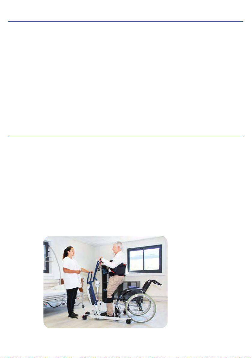
• How to properly use a stand-up lift (1.):
- Low-tonicity patients shall be transferred in a “semi-seated” position
Instructions for Use
Your stand is designed to lift people, so do not use it for other purposes.
• Check that the patient’s weight does not exceed the maximum weight that the lifter
can lift.
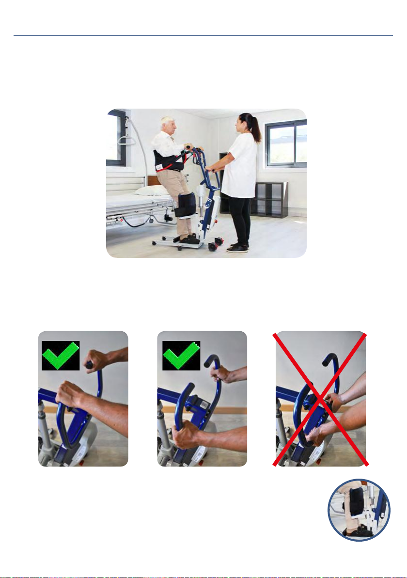
• Do not force the controls and devices of the stand, they are all easy to use and do not
need force.
• Maneuver the stander by pushing the handles or handles, never pushing the patient.
• Carefully manipulate the stander when transferring a patient and at a speed appro-
priate to the situation.
• Move with the stand on flat, smooth surfaces. It is not recommended to use it on a
slope of more than 5 °: if you are obliged to circulate on a ramp, it is advised that a
second person helps you. Never use an electric stander under a shower.
• Never charge a stand-up battery near a bath or shower.
Instructions for Use
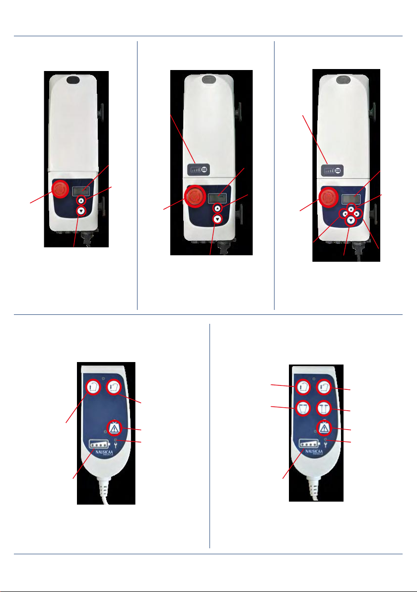
Example with a Wayup 5 with
Mechanical opening legs
5
User Manual - Stand-Up Lift: WAYUP 5 Range
Manufactured by NAUSICAA Médical S.A.S. / Approved by Ghizlane Labrosse (Biomedical Engineer)

Stand-up Lifts Use
6
• Furthermore, the handlebar must be used to push and/or pull the device with
the hands on the upper part or on the sides, not below pushing upward.
• How to properly use a stand-up lift (2):
- Medium-tonicity patients shall be transferred in a standing position
• Likewise, the patient’s shins must be in contact with the shin
block at all times.
• In all cases, the caregiver must be properly trained for the safe
handling of the device.
User Manual - Stand-Up Lift: WAYUP 5 Range
Manufactured by NAUSICAA Médical S.A.S. / Approved by Ghizlane Labrosse (Biomedical Engineer)

Before use, check that the
actuator and the hand-
control are correctly
connected to the control
unit (page 17)
Check the status of the
control box and the battery
Check that the actuator is properly secured
Check that the battery is charged
Stand-up Lifts Use
7
Control Box 2 Functions Control Box 4 Functions
User Manual - Stand-Up Lift: WAYUP 5 Range
Manufactured by NAUSICAA Médical S.A.S. / Approved by Ghizlane Labrosse (Biomedical Engineer)

Lead Model
Without Display
Lithium Model
With 2 Functions Display
Model with display
2 functions
Lithium Model
With 4 Functions Display
Model with display
4 functions
Motorisation Informations
Battery
level
indication
LCD
display
Down
Down Opening
Closing
Down
LCD
display
Up
Up
Up
LCD
display
Emergency
stop button
Battery
level
indication
Battery
level
indication
Emergency
stop button
The products concerned are:
WAYUP 5, WAYUP 5 with mecha-
nical opening legs
The products concerned are:
WAYUP 5, WAYUP 5 with mechanical opening legs
The products concerned are:
WAYUP 5 Plus with electrical opening legs
The products concerned are:
WAYUP 5, WAYUP 5 with mecha-
nical opening legs
The products concerned are:
WAYUP 5 Plus with electrical
opening legs
Up
Up
Opening
Battery level
indication Battery level
indication
Closing
Down
Closing
Overload Overload
Maintenance Maintenance
8
User Manual - Stand-Up Lift: WAYUP 5 Range
Manufactured by NAUSICAA Médical S.A.S. / Approved by Ghizlane Labrosse (Biomedical Engineer)

Slings Use
Operate the actuator until
halfway.
Operate the
actuator until
it stops.
Transfer in sitting position for
ALL PATIENTS
Handlebar in lower position:
Position the yellow loops on
the cental hooks of the hand-
lebar.
Handlebar in lower position:
Position the green loops on the central
hooks of the handlebar.
Position the “under thighs“
strap and close it adjus-
ting it without tightening
too much.
Standing up for PATIENT WITH CHEST TONICITY
INSTRUCTIONS FOR USE
Position the bottom of the backrest in the lumbar region in order that the ears of the
attachment system are on either side of the person.
Place the fasteners of the backrest under the arms of the person.
Close the plastron.
Hook the two fasteners of the backrest to the stand-up lift hooks.
SETTINGS
The fastening system, with multiple hangers, allows to adjust the position of the person.
9
User Manual - Stand-Up Lift: WAYUP 5 Range
Manufactured by NAUSICAA Médical S.A.S. / Approved by Ghizlane Labrosse (Biomedical Engineer)

Slings Use
CAUTION
Important Recommandations
In order to get a maximum efficiency of these sort of product, it is necessary :
- to choose the appropriate size for the patient
- to get the best possible adjustment to the patient
These products must not be in direct contact with a wounded skin.
Read the instruction manual before using the slings.
The backrest hangers must be hung on the same color.
Before lifting a person with the stand-up lift, make sure the sling is securely hooked to
the hooks.
Choosing the right sling size is important in order to achieve the highest possible patient
comfort and safety.
An assessment of the patient capacity is required before using a stand-up
lift and more precisely to make sure that the patient can bear weight on
at least one leg and has sufficient tonicity in the lower and upper parts
of the body.
Our R&D department has put in place a size colour-code in order to quickly identify the
size of each sling:
- Size TU (One size fits) Black
- Size S Yellow
- Size M Red
- Size L Green
- Size XL Blue
- Size 2XL Orange Light
- Size 3XL Orange
- Size 4XL Orange Dark
SIZES TU S M L XL 2XL 3XL 4XL
WAIST SIZE 70/140 70/90 90/115 115/140
140/165 154/186
172/206
196/232
BETWEEN SIZE
AND HIPS 70/140 70/90 90/115
115/140 140/165 154/186 172/206 196/232
10
User Manual - Stand-Up Lift: WAYUP 5 Range
Manufactured by NAUSICAA Médical S.A.S. / Approved by Ghizlane Labrosse (Biomedical Engineer)

Labelling on the box
Reuse
The stand-up lift is suitable for repeated use.
The stand-up lift must be cleaned, disinfected and serviced according to the Preventive
Maintenance and Security Controls (pages 14-15) at the very latest just before the reuse.
Labelling
Conditions
de Transport
&de Stockage
Conditions
de Transport
&de Stockage
Conditions
de Transport
&de Stockage
Conditions
de Transport
&de Stockage
12 Allée du Piot
ZA Pôle Actif
30660 Gallargues le Montueux-FRANCE
Tel: +33 4 66 51 50 80
Fax: +33 4 66 51 50 47
Web: www.nausicaa-medical.com
12 Allée du Piot
ZA Pôle Actif
30660 Gallargues le Montueux-FRANCE
Tel: +33 4 66 51 50 80
Fax: +33 4 66 51 50 47
Web: www.nausicaa-medical.com
12 Allée du Piot
ZA Pôle Actif
30660 Gallargues le Montueux-FRANCE
Tel: +33 4 66 51 50 80
Fax: +33 4 66 51 50 47
Web: www.nausicaa-medical.com
12 Allée du Piot
ZA Pôle Actif
30660 Gallargues le Montueux-FRANCE
Tel: +33 4 66 51 50 80
Fax: +33 4 66 51 50 47
Web: www.nausicaa-medical.com
v03.01/18
v03.01/18
v03.01/18
v03.01/18
CHÂSSIS
CHÂSSIS
CHÂSSIS
CHÂSSIS
BATTERIE
BATTERIE
BATTERIE
BATTERIE
11
User Manual - Stand-Up Lift: WAYUP 5 Range
Manufactured by NAUSICAA Médical S.A.S. / Approved by Ghizlane Labrosse (Biomedical Engineer)

Labelling
1
2
3
4
5
• Regularly recharge the battery at the maximum.
• Making small incomplete charges shortens the battery life.
• The battery should not be exposed to temperatures neither too
low nor too high.
• The batteries status depends on the maintenance and therefore
can not be under warranty.
•
It is important to check the charger if the battery no longer works.
BATTERY
MAINTENANCE
A POORLY MAINTAINED BATTERY DETERIORATES
SAFETY INSTRUCTIONS
BEFORE EACH USE
• Verify the presence and conditions of safety devices: all axis and their
constrained fixations (pins, clips and bolts) and the tightness of the screws (see
user manual).
DO NOT USE THE DEVICE IN CASE OF ANY LACK OR BAD OVERALL STATE
• Check the perfect condition of the hoist sling.
• Check the perfect condition of the traction sling (EASYLEV, NAUSILEV).
180 kg
12
User Manual - Stand-Up Lift: WAYUP 5 Range
Manufactured by NAUSICAA Médical S.A.S. / Approved by Ghizlane Labrosse (Biomedical Engineer)
6
7 8

Labelling
13
For all models of the WAYUP 5 Range
User Manual - Stand-Up Lift: WAYUP 5 Range
Manufactured by NAUSICAA Médical S.A.S. / Approved by Ghizlane Labrosse (Biomedical Engineer)
1
5
3
4
278

General Safety Guidelines
1. Use the Stand-Up Lift only for its intended purpose, in accordance with the legislation for medi-
cal devices, the regulations for labor protection and accident prevention, as well as the generally
recognized rules of technology.
2. Note that the Stand-Up Lift is a medical device, therefore the user is required to comply with the
directive on the use of medical devices.
3. The requirements for the electrical installation of the room or area where the Stand-Up Lift is
used must meet the current state of the technology.
4. Using the Stand-Up Lift only after being trained for its handling.
5. Before using the device, please read the complete User Manual in order to avoid damage due
to improper handling or exposure to risks. The User Manual contains important information and
notes required for the Stand-Up Lift use.
6. Use the Stand-Up Lift in accordance with this User Manual only. Keep the User Manual for future
reference in case of questions. Join this User Manual to the Stand-Up Lift in case of change of
ownership.
7. Before any use, it must be ascertained whether the Stand-Up Lift and its accessories are in wor-
king order and in impeccable conditions.
8. Before using the Stand-Up Lift with other medical and non-medical devices, check that the
combination of these products is allowed and can be used together safely.
9. Assembly, commissioning, maintenance and repair of the Stand-Up Lift should be entrusted
only to specialists.
10. It is up to the user or operator to ensure (through adequate measures and instructions) that
mechanical stress of the charging cord (through bending, tension, shear, crushing) is excluded
during loading or cleaning of the part. This also applies to the electrical cables of other devices
used with the Stand-Up Lift.
11. Respect the activation duration and the maximum weight capacity. These values must not be
exceeded, otherwise the Stand-Up Lift safe operation is no longer guaranteed.
12. Do not expose the Stand-Up Lift to direct sunlight or heat.
13. Ensure that no moisture enters the electrical system.
14. Avoid mechanical stress on electrical cords. Pull, bend or crush the cords may damage them.
15. Charge batteries in a well ventilated area.
16. Electromagnetic interferences can not be excluded from the Stand-Up Lift and other devices.
If there is a risk of such interference, the source of interference must be removed or the Stand-Up
Lift should not be used.
17. Disruptions caused by the use of portable communication devices can not be completely
excluded. This is why a safe distance of at least 3 meters must be kept in order to ensure the
functioning of the Stand-Up Lift safely.
18. Do not leave unattended children stand near the Stand-Up Lift.
19. The Stand-Up Lift should not be used as soon as abnormal noises, damages or any other mal-
functions occur. In this case, do not connect the wall charger to the Stand-Up Lift and inform us.
20. If damaged or defective, the Stand-Up Lift should not be used and should not be connected to
the direct current. Inform the dealer to remedy the default or failure.
14
User Manual - Stand-Up Lift: WAYUP 5 Range
Manufactured by NAUSICAA Médical S.A.S. / Approved by Ghizlane Labrosse (Biomedical Engineer)

15
• Frame made in steel
• Laser cutting and bending sheet metal, tubes and profiles
• Epoxy baked painting
• Ball bearing castors
• Lifespan : 8 years (except electrical parts)
* SCP : Suspention central point
Technicals & Dimensionals Characteristics
MODELS CONCERNED WAYUP 5 FIXED BASE
User Manual - Stand-Up Lift: WAYUP 5 Range
Manufactured by NAUSICAA Médical S.A.S. / Approved by Ghizlane Labrosse (Biomedical Engineer)
thedimensionsareinmillimeters WAYUP5-SB-PF WAYUP5ECP-SB-PF WAYUP5PLUS-SB-PF
Cylinderdistanceatmaximumreach
Position1:340
Position2:365
Position3:390
Position1:340
Position2:365
Position3:390
Position1:340
Position2:365
Position3:390
Basedistanceatmaximumrange
Position1:320
Position2:345
Position3:370
Position1:320
Position2:345
Position3:370
Position1:320
Position2:345
Position3:370
Maximumheight
Lowhandles
Position1:1275
Position2:1300
Position3:1320
Handleshigh
Position1:1280
Position2:1305
Position3:1325
Lowhandles
Position1:1297
Position2:1322
Position3:1342
Handleshigh
Position1:1302
Position2:1327
Position3:1347
Lowhandles
Position1:1297
Position2:1322
Position3:1342
Handleshigh
Position1:1302
Position2:1327
Position3:1348
Minimumheight
Lowhandles
800
Handleshigh
910
Lowhandles
822
Handleshigh
931
Lowhandles
822
Handleshigh
932
liftingamplitude 520 520 520
maximumwidth 565 890 800
Distancefrombasetointernalwidth700mm(applicabletofootgauge
versions)/minimumexternalwidth(fixedversions) 340
400 560
internalwidthatmaximumrange 240
350 370
minimuminteriorwidth 240 350 370
groundclearance 25 45 45
footheight 68 112 112
distancefromthedevicetothemaximumheight 715 800 800
distancefromthedevicetothemaximumrange 320 390 390
roundingdiameter 940 1100 1100
totallength 945 1070 1070
totalwidthclosedfeet 565 540 520
Maximumcharge 180kg 180kg 180kg
Totalweightofthedevice 29kg 36kg 38kg
Massoftheheaviestpiece BASE=10kg BASE=7kg BASE=7kg

16
MODELS CONCERNED WAYUP 5 with mechanical opening legs,
WAYUP 5 PLUS with electrical opening legs
Technicals & Dimensionals Characteristics
User Manual - Stand-Up Lift: WAYUP 5 Range
Manufactured by NAUSICAA Médical S.A.S. / Approved by Ghizlane Labrosse (Biomedical Engineer)
• Frame made in steel
• Laser cutting and bending sheet metal, tubes and profiles
• Epoxy baked painting
• Ball bearing castors
• Lifespan : 8 years (except electrical parts)
* SCP : Suspention central point
thedimensionsareinmillimeters WAYUP5-SB-PF WAYUP5ECP-SB-PF WAYUP5PLUS-SB-PF
Cylinderdistanceatmaximumreach
Position1:340
Position2:365
Position3:390
Position1:340
Position2:365
Position3:390
Position1:340
Position2:365
Position3:390
Basedistanceatmaximumrange
Position1:320
Position2:345
Position3:370
Position1:320
Position2:345
Position3:370
Position1:320
Position2:345
Position3:370
Maximumheight
Lowhandles
Position1:1275
Position2:1300
Position3:1320
Handleshigh
Position1:1280
Position2:1305
Position3:1325
Lowhandles
Position1:1297
Position2:1322
Position3:1342
Handleshigh
Position1:1302
Position2:1327
Position3:1347
Lowhandles
Position1:1297
Position2:1322
Position3:1342
Handleshigh
Position1:1302
Position2:1327
Position3:1348
Minimumheight
Lowhandles
800
Handleshigh
910
Lowhandles
822
Handleshigh
931
Lowhandles
822
Handleshigh
932
liftingamplitude 520 520 520
maximumwidth 565 890 800
Distancefrombasetointernalwidth700mm(applicabletofootgauge
versions)/minimumexternalwidth(fixedversions)
340 400 560
internalwidthatmaximumrange
240 350 370
minimuminteriorwidth 240 350 370
groundclearance 25 45 45
footheight 68 112 112
distancefromthedevicetothemaximumheight 715 800 800
distancefromthedevicetothemaximumrange 320 390 390
roundingdiameter 940 1100 1100
totallength 945 1070 1070
totalwidthclosedfeet 565 540 520
Maximumcharge 180kg 180kg 180kg
Totalweightofthedevice 29kg 36kg 38kg
Massoftheheaviestpiece BASE=10kg BASE=7kg BASE=7kg
thedimensionsareinmillimeters WAYUP5-SB-PF WAYUP5ECP-SB-PF WAYUP5PLUS-SB-PF
Cylinderdistanceatmaximumreach
Position1:340
Position2:365
Position3:390
Position1:340
Position2:365
Position3:390
Position1:340
Position2:365
Position3:390
Basedistanceatmaximumrange
Position1:320
Position2:345
Position3:370
Position1:320
Position2:345
Position3:370
Position1:320
Position2:345
Position3:370
Maximumheight
Lowhandles
Position1:1275
Position2:1300
Position3:1320
Handleshigh
Position1:1280
Position2:1305
Position3:1325
Lowhandles
Position1:1297
Position2:1322
Position3:1342
Handleshigh
Position1:1302
Position2:1327
Position3:1347
Lowhandles
Position1:1297
Position2:1322
Position3:1342
Handleshigh
Position1:1302
Position2:1327
Position3:1348
Minimumheight
Lowhandles
800
Handleshigh
910
Lowhandles
822
Handleshigh
931
Lowhandles
822
Handleshigh
932
liftingamplitude 520 520 520
maximumwidth 565 890 800
Distancefrombasetointernalwidth700mm(applicabletofootgauge
versions)/minimumexternalwidth(fixedversions)
340
400 560
internalwidthatmaximumrange 240
350 370
minimuminteriorwidth 240 350 370
groundclearance 25 45 45
footheight 68 112 112
distancefromthedevicetothemaximumheight 715 800 800
distancefromthedevicetothemaximumrange 320 390 390
roundingdiameter 940 1100 1100
totallength 945 1070 1070
totalwidthclosedfeet 565 540 520
Maximumcharge 180kg 180kg 180kg
Totalweightofthedevice 29kg 36kg 38kg
Massoftheheaviestpiece BASE=10kg BASE=7kg BASE=7kg

17
Device of
class II
• Removable battery pack
• Digital display of the autonomy
• Emergency stop
• Electrical security lowering system
• Wall charger (in option)
• Remote control 4 functions
• Conform to Standard EN 60601-1
• DC motor low voltage 24V
• 24V / 120VA power
• Maximum strength: 8000 N
• Electrical opening actuator power: 3000 N
(Models : WAYUP 5 with electrical opening legs)
• Lifting stroke : 11 cm
• Electronic protection when overloaded
• Protections types :
- Télécommande: IP56
- Remote control: IP54
- Control box: IP65
- Battery pack: IP65
- Actuator: IP55
• Stop limit switch
• Box in ABS
• Handcontrol with spiral cable, low voltage 24V
• Protection against overloading through thermo-switch
• Loudness : less than 55dB at a distance of 1 meter.
• Electromagnetic compatibility : conforms to EN 60601-1-2
Technicals & Dimensionals Characteristics
Battery Charging Diagram :
User Manual - Stand-Up Lift: WAYUP 5 Range
Manufactured by NAUSICAA Médical S.A.S. / Approved by Ghizlane Labrosse (Biomedical Engineer)

Detail of the features of the Control Box:
1. Display information:
- To view the information stored in the control box, press the Up and
Down buttons on the housing for 5 seconds.
2. Factor of operation:
- Recognizes for the cylinder (Up / Down) the non-compliance with
the rest time of the cylinder.
3. Overloading cylinder # 1:
- Counts the number of times an attempt to transfer a person wei-
ghing beyond the maximum limit reached is made. When this is the
case, the cylinder will stop and an anvil will be displayed. It will then
be impossible to continue the operation of the device.
4. Overload of cylinder # 2:
- Count the number of times an attempt is made to move or close
the feet while the feet are stuck. When this is the case, the cylinder
will stop and an anvil will be displayed. It will then be impossible to
continue the operation of the device.
5. Incomplete charge:
- Counts all incomplete charges in the battery below 24.6V. This
number corresponds to the number of charges that damage the
battery.
6. Usage time:
- Displays the cumulative usage time of the device. From 600,000
seconds of use, the maintenance key is displayed - it is necessary to
perform a complete control of the device.
7-List of error codes:
E001: Required time setting
E002: Low battery charge level
E003: Abnormal operating time (duty factor)
E004: Cylinder overload N ° 1
E005: Cylinder overload N ° 2
E006: Maintenance required (600,000 seconds)
Motorisation Technicals Characteristics
18
2. Facteur de marche :
- Comptabilise pour le vérin (Montée/Descente) le non-respect du temps
de repos du vérin.
3. Surcharge du vérin #1 :
- Comptabilise le nombre de fois où une tentative de transfert de personne
pe-sant au-delà de la limite maximale atteinte est effectuée. Quand ce sera la
cas, le vérin va s’arrêter et une enclume s’affichera. Il sera alors impossible de
pour-suivre le fonctionnement de l’appareil.
4. Surcharge du vérin #2 :
- Comptabilise le nombre de fois où une tentative d’écartement ou de
ferme-ture des pieds est effectuée alors que ces derniers sont coincés. Quand
ce sera la cas, le vérin va s’arrêter et une enclume s’affichera. Il sera alors
impossible de poursuivre le fonctionnement de l’appareil.
5. Charge incomplète :
- Comptabilise toutes les charges incomplètes de la batterie inférieures à
24,6V. Ce chiffre correspond au nombre de charges détériorant la batterie.
6. Temps d’utilisation :
- Affiche le cumul du temps d’utilisation de l’appareil. À partir de 600 000
se-condes d’utilisation, la clé de maintenance s’affiche - il est alors
indispensable de réaliser un contrôle complet de l’appareil.
7-Liste des codes erreurs :
E001 : Mise à l’heure requise
E002 : Niveau de charge batterie faible (low batterie)
E003 : Durée de fonctionnement anormale (facteur de marche)
E004 : Surcharge vérin N°1
E005 : Surcharge vérin N°2
E006 : Maintenance requise (600 000 secondes)
Détail des fonctionnalités du Boitier de contrôle :
1. Affichage des informations :
- Pour afficher les informations enregistrées dans le boîtier de contrôle,
appuyer sur les boutons Montée et Descente du boîtier pendant 5 secondes.
User Manual - Stand-Up Lift: WAYUP 5 Range
Manufactured by NAUSICAA Médical S.A.S. / Approved by Ghizlane Labrosse (Biomedical Engineer)
This manual suits for next models
4
Table of contents
Other NAUSICAA Lifting System manuals
Popular Lifting System manuals by other brands

LSP inc.
LSP inc. LS5013BU Assembly instructions

Enerpac
Enerpac SLVS-8 instruction sheet

HIRD GLASS
HIRD GLASS KAPPEL HYDRAULICA 1200 CURVED Operator's manual

Dino lift
Dino lift DINO XT II 160 operating instructions

Bend-Pak
Bend-Pak XPR-10 Series Installation and operation manual

Bend-Pak
Bend-Pak XPR-12FDL Service manual