Proslat Garage Gator 68221 User manual

68221 21/01/2019
Model: 68221
RESIDENTIAL MOTORIZED
STORAGE LIFT 220 LB CAPACITY
ASSEMBLY INSTRUCTIONS, USE & CARE GUIDE AND WARRANTY
Questions, problems, missing parts? Before returning to the store, call Proslat/Garage Gator Customer Service
1-888-GATOR-08 8 a.m. – 5 p.m., EST, Monday – Friday / [email protected]
PROSLAT.COM
By
Watch our installation video at proslat.com/pages/instructions
This is the best way to follow and understand the installation process

2
Table of Contents
WHAT IS COVERED
□Only the Motorized lift in possession of the rst retail purchaser.
□Defects in material or workmanship guaranteed one year.
WHAT IS NOT COVERED
□Product failure that results from improper installation, misuse or
abuse, alteration, or any other failure not related to defects in
materials or workmanship.
□Damage due to acts of God, re, or accident.
Warranty
□Damage created by non-Manufacturer developed
accessories.
□Damage that results from loading the lift beyond the stated
maximum weight capacity.
□Corrosion, rust or discoloration of nish.
□The cost of return, labour, or accessory materials.
Warranty ......................................................................................................................................................................... 2
Safety Information.......................................................................................................................................................... 3
Hardware and required tools ......................................................................................................................................... 4
Tools required............................................................................................................................................................... 4
Hardware Included. ...................................................................................................................................................... 4
Carton inventory ........................................................................................................................................................... 5
Components ................................................................................................................................................................. 5
Pre-installation ............................................................................................................................................................... 6
Determine motor mounting location on the ceiling ...................................................................................................... 7
Installation...................................................................................................................................................................... 8
STEP 1 – Prepare ceiling .............................................................................................................................................. 7
STEP 2 – Install the motor mounting plate to the ceiling ............................................................................................. 8
STEP 3 – Attach the motor hoist to the motor mounting plate ..................................................................................... 9
STEP 4 – Connect and install the rst spacer channel bar ........................................................................................ 11
STEP 5 – Connect and install the second spacer channel bar ................................................................................... 12
STEP 6 – Connect and install the spacer channel pulley bar ..................................................................................... 13
STEP 7 – Install the strap over the channel bar pulley............................................................................................... 14
STEP 8 – Install the hand control switch holder hook................................................................................................ 15
STEP 9 – Assemble the hook bar................................................................................................................................ 16
STEP 10 – Level ......................................................................................................................................................... 17
STEP 11 – Using the key lock feature ........................................................................................................................ 18
STEP 12 – Test the unit............................................................................................................................................... 18
Operation instructions.................................................................................................................................................. 19
Contact information/Maintenance/Specification........................................................................................................ 19
Safety Information
WARNING: When you see the safety symbol on the following pages this will alert you of the possibility of serious injuries or death if you
do not comply with the corresponding instructions. The hazard may come from something mechanical or for the electrical shock. Read the
instructions carefully!
WARNING
To reduce the risk of severe injury or death:
1. READ AND FOLLOW ALL SAFETY, INSTALLATION AND OPERATION INSTRUCTIONS. If you have any questions
or do not understand an instruction contact GARAGE GATOR AT 1 888 691-2944.
2. Do not use to lift people or animals.
3. Do not use to support a load over people or animals.
4. Never operate while hand(s) are near moving parts.
5. Do not stand under lift.
6. Let unit cool down for 5 minutes after cycle.
7. Install on a at level ceiling, or open rafters. Will not operate correctly if installed on an angle.
8. Visually inspect trusses for damage before installing your Garage Gator 68221.
WARNING: THIS IS A DO IT YOURSELF (DIY) PROJECT. DO NOT ATTEMPT THIS INSTALLATION WITHOUT A BASIC
UNDERSTANDING OF THE CONTENTS IN THESE ASSEMBLY INSTRUCTIONS. IF YOU ARE NOT CONFIDENT WITH
LOCATING AND ANCHORING THE GARAGE GATOR TO THE CEILING JOISTS, DO NOT ATTEMPT THIS INSTALLATION
WITHOUT SOMEONE WHO IS.
WARNING: DO NOT EXCEED THE WEIGHT LIMITS (Based on model used)
WARNING: This weight limit is based on all lag bolts being secured in the CENTER of the joists a wood framed
garage. The joists must have a minimum 2 x 6 in. (standard lumber) cross section, 24 in. (or less) apart, with
at least 2 in. of penetration from each lag screw used. For truss framed garage ceiling structures, joists with a
2 x 4 in. (bottom truss cord) cross section is acceptable.
Do not climb on or (if you have a platform) do NOT hang from.
BOTTOM LINE… BE CAREFUL, THESE INSTRUCTIONS, WARNINGS AND NOTES DO NOT REPLACE YOUR SOUND
JUDGMENT AND DECISION MAKING. IF, FOR ANY REASON, YOU FEEL THE QUALITY OF YOUR CEILING STUCTURE
IS IN QUESTION, DISCONTINUE THE INSTALLATION PROCESS IMMEDIATELY. USE THE GARAGE GATOR WISELY
AND ENJOY RECLAIMING YOUR GARAGE!
3 PROSLAT.COM
Please contact 1-888-801-1801 for further assistance.
4
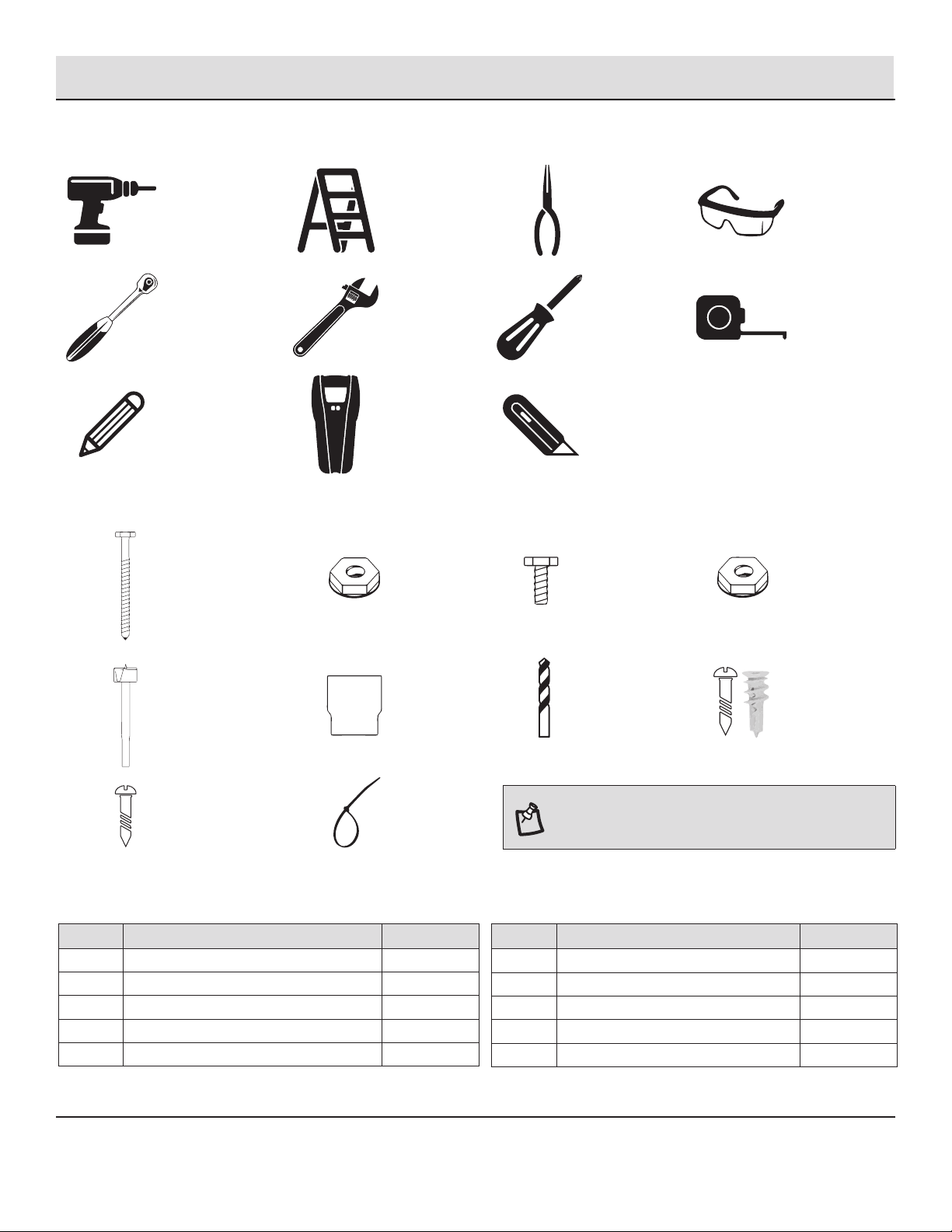
TOOLS REQUIRED
Power drill Step ladder Pliers Safety
glasses
Ratchet
Adjustable,
open ended
wrench
Phillips
screwdriver
Tape
measure
Pencil Stud nder Utility
knife
HARDWARE INCLUDED
K x 12
4 in. Lag bolt
L x 4
5⁄16 in. nut
P x 2
¼ in. x ½ in.
bolt
Q x 1
¼ in. (6 mm)
lock nut
R x 1
15 mm hole saw
drill bit
T x 1
½ in (13 mm)
socket
U x 1
1⁄8in. drill bit
V x 2
Drywall screw
(25 mm)
& plug
W x 10
30 mm screw
X x 2
Cable tie
200mm
NOTE: Drawings & photos for illustrative purposes only —
actual parts may vary from pictures. Parts are not shown
actual size.
Hardware and required tools
Parts Description Quantity
K 4 in. Lag bolt 12
L5⁄16 in. nut 4
P ¼ in. x ½ in. bolt 2
Q ¼ in. (6 mm) lock nut 1
R 15 mm hole saw drill bit 1
Parts Description Quantity
T 13 mm socket 1
U1⁄8in. drill bit 1
V Drywall screw & plug 2
W 30 mm screw 10
X Cable tie 200 mm 2
CARTON INVENTORY
Carefully inspect your new motorized storage unit for any possible damage and/or shortage of parts. Separate all major components and
parts as detailed below. Do not attempt installation if parts are damaged or missing. If parts of your lift are missing or appear damaged
call Proslat/Garage Gator customer service at 1 888 GATOR-08, Monday through Friday, 8:00 AM to 5:00 PM Eastern Time. Before calling
carefully check the carton as parts may be in the packing material.
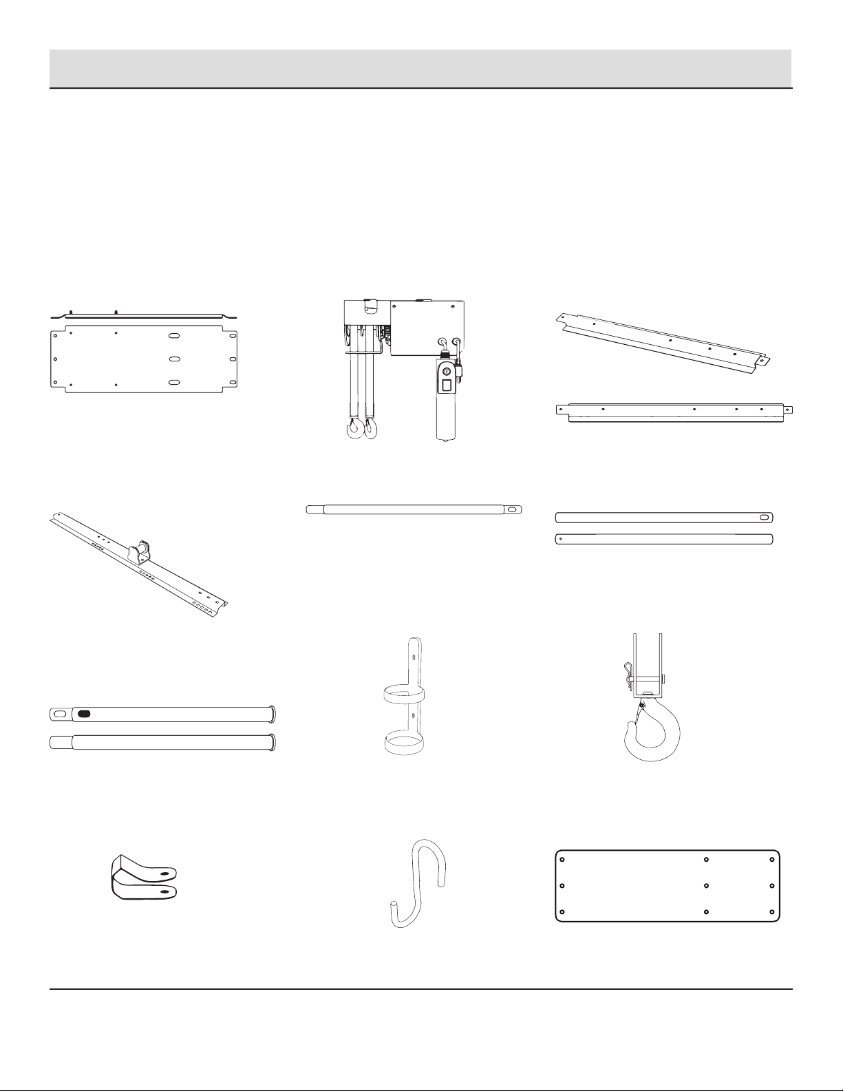
COMPONENTS
(A) Motor Mounting Plate (C) Spacer channel bar x 2
(B) Motor hoist
(D) Spacer channel pulley bar (F) Hook Bar Connector x 2
(N) Paper motor mounting plate template x 1
(J) Power cord cable clamps x 10
Hardware and required tools
(E) Hook bar Center x 1
(G) Hook Bar End x 2
(M) Hooks x 8
(I) Height adjustment bracket
(H) Hand control switch holder hook x 1
5 PROSLAT.COM
Please contact 1-888-801-1801 for further assistance.

6
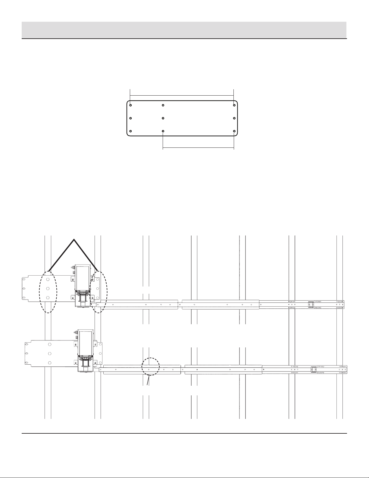
Perpendicular to joist installations Parallel to joist installations
OPTION A OPTION C
OPTION D
Pre-Installation
Determine motor mounting location on the ceiling
□Choose a location in your garage where you would like to install your Garage Gator model 68221 – an unobstructed operating space
of at least 3 feet by 4 feet is required. The motor mounting plate (A) should be installed at least 3 feet away from walls or any other
obstructions and close to a power supply (preferably a ceiling outlet).
□The motorized lift is designed to be installed either perpendicular or parallel to the ceiling joists and can be installed on joists with
16in. or 24in. spacing.
□In the chosen installation area determine the direction of the ceiling joists and the exact location of the ceiling joists by visually
checking or using a joist nder or a very ne drill bit.
□Four installation options are illustrated below. Note how the motor mounting plate (A) and motor hoist (B) are positioned for your
installation – in particular the location of the 4 xed threaded bolts on the motor mounting plate and the 4 ½ in. spacer channel bar
attachment tab on the motor hoist. Determine how the motor mounting plate should be rotated – where the xed, threaded bolts
should be located – prior to fastening to the joists. Identify your installation option.
ENSURE YOUR MOTOR MOUNTING
PLATE IS ROTATED PROPERLY
BEFORE PLACING THE MOTOR
MOUNTING PLATE ON CEILING.
MOTOR
DIRECTION
OPTION B
Watch our installation video at proslat.com/pages/instructions
This is the best way to follow and understand the installation process.
Installation
□Position the paper motor mounting template (N) in the installation location and mark with a pencil the six spots where the
lags bolts will be fastened.
□It is very important that the wood screws are fastened to the center of the joists. Use the hole saw drill bit (U) or cut away
the drywall with a utility knife to obtain an unobstructed view of the width of the joists so the exact center can easily be
determined (covered ceilings only). It may be necessary to again use the motor mounting template and a pencil to mark
where the wood screws are to be fastened.
16 IN. JOISTS
EXAMPLE OF BAD ALIGNMENT
FAILURE TO PROPERLY INSTALL YOUR MOUNTING PLATE TO
THE CENTER OF YOUR JOISTS WILL CAUSE YOUR SPACER
BAR TO BE OFFSET FROM CENTER OF JOISTS.
MAKE SURE YOU MOUNT TO THE CENTER
OF EACH JOIST TO SECURE YOUR GARAGE
GATOR PROPERLY
MARK THESE SIX HOLES FOR 16 IN. JOIST CENTERS
MARK THESE SIX HOLES FOR 24 IN. JOIST CENTERS
1 Prepare ceiling
7 PROSLAT.COM
Please contact 1-888-801-1801 for further assistance.

8
x 6 x 1
WARNING: Motor mounting plate must
be fastened to wooden joists in the building
framing. Do not fasten to drywall, particle board,
plaster or other such materials. Failure to do
this may result in injury or death.
2 Install the motor mounting plate to the ceiling
□Using a power drill with a 1/8in. drill bit attached drill six pilot holes into the center of the joists.
□Using the ratchet and ½ in. socket (T) fasten 6 of the 4 in. lag bolts (K) into the joists until the motor mounting plate is securely
fastened.
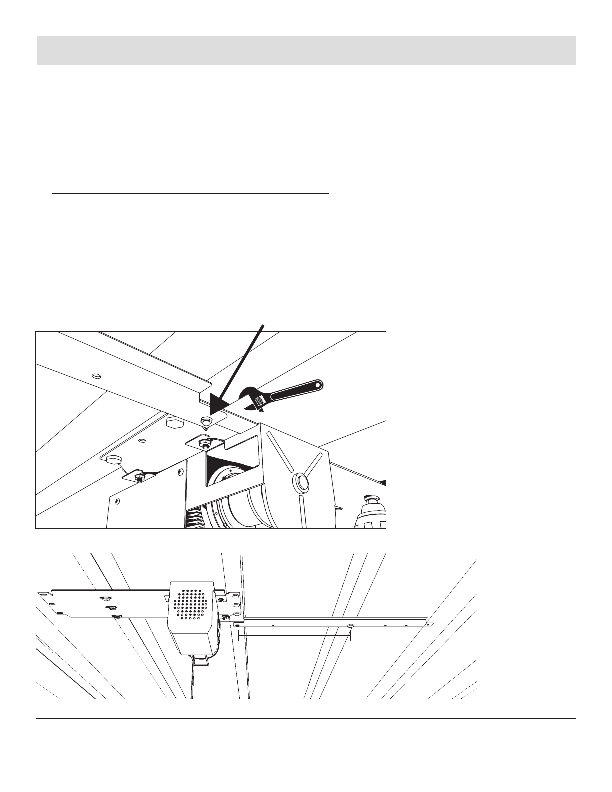
Installation (continued)

WARNING: Slide the motor hoist until the tabs are rmly
against the threaded bolts. Do not leave any space between
the bolts and the enclosed end of the mounting tabs.
3 Attach the motor hoist to the motor mounting plate.
□Slide the mounting tabs on the motor hoist (B) over the top of the four xed, threaded bolts on the motor mounting plate (A) (If there is
not enough room between the washers and the motor mounting plate for the motor hoist mounting tabs it will be necessary to loosen
the nuts by turning them counter clockwise.)
□Once the motor hoist is properly positioned on the motor mounting plate tighten the nut with the ratchet or the adjustable wrench until
the motor hoist is securely attached to the motor mounting plate.
Installation (continued)
9 PROSLAT.COM
Please contact 1-888-801-1801 for further assistance.

10
0 PO
24 PO
48 PO
72 PO
96 PO
0 PO
16 PO
32 PO
48 PO
64 PO
80 PO
96 PO
Pre-Installation (continued)
SPACER CHANNEL BAR
SPACER CHANNEL BAR
SPACER CHANNEL BAR
CHANNEL BAR
CONNECTING HOLE
CHANNEL BAR
CONNECTING HOLE
CHANNEL BAR
CONNECTING HOLE
CHANNEL BAR
CONNECTING HOLE
SPACER CHANNEL
PULLEY BAR
SPACER CHANNEL
PULLEY BAR
SPACER CHANNEL BAR
16 in. joists24 in. joists
Depending on your joist spacing, you will use different holes on the spacer bars for installation.
16"
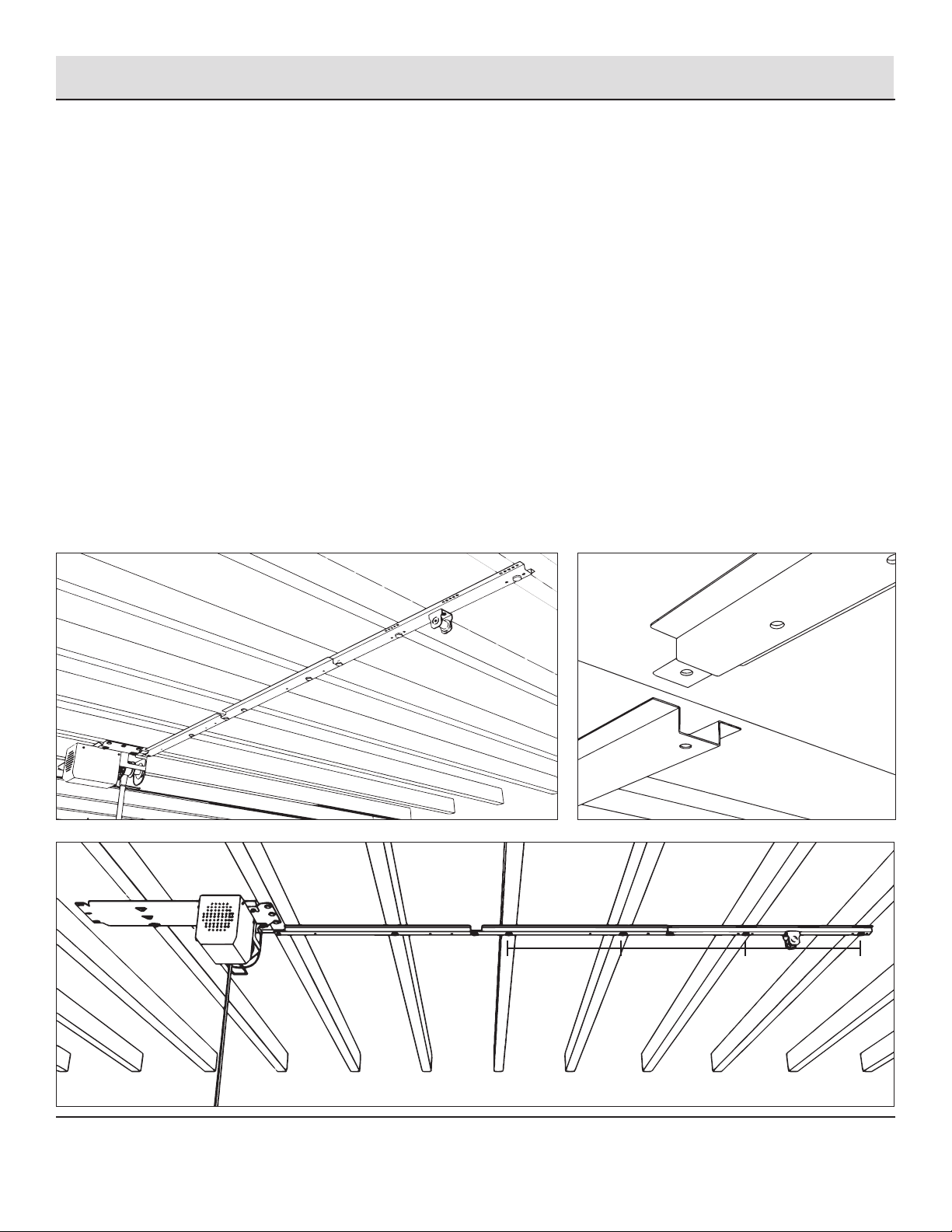
Installation (continued)
4 Connect and install the rst spacer channel bar
□Press the spacer channel bar ush with the ceiling and mark ceiling with a pencil where a lag bolt will be used to attach the bar to the
joist.
– Perpendicular joist installation (option A or B on page 6). Make a mark at either the 16 in. hole or 24 in. hole depending on your joist
spacing. Remove the spacer channel bar.
– Parallel joist installation (option C or D on page 6). Make a mark at the 21 in. hole.
Remove the spacer channel bar.
□It is very important that the lag bolt is fastened to the center of the joist. Use the hole saw drill bit (R) or cut away the drywall with a
utility knife to obtain an unobstructed view of the width of the joist so the exact center can easily be determined. It may be necessary
to reposition the spacer channel bar and mark with a pencil where the lag bolt is to be fastened.
□Using a power drill with a 1/8 in. drill bit attached drill a pilot hole into the center of the joist.
□Insert the ared end (the end without a xed nut) of a spacer channel bar onto the xed bolt coming down from the motor plate tab
above the strap spools on the motor hoist.
□Attach a 6 mm nut (Q) to the xed bolt and tighten with a ratchet or adjustable wrench until the spacer channel bar is securely
fastened to the motor hoist.
□Place a lag bolt(s) (K) and using the ratchet fasten the bolt(s) into the joist(s) until the spacer channel bar is securely fastened.
11 PROSLAT.COM
Please contact 1-888-801-1801 for further assistance.

12
16"
16"
5 Connect and install the second spacer channel bar
□Line up the hole in the ared end (the end without a xed nut) of the spacer channel bar (C) over the hole in the installed spacer
channel pulley bar. Thread a ¼ in. x ½ in. bolt (P) into the hole and nger tighten.
□Press the spacer channel bar ush with the ceiling and mark with a pencil where the lag bolt(s) will be used to attach the bar to the
joist(s).
□– PERPENDICULAR JOIST INSTALLATION (option A or B on page 6). There are holes in the spacer channel bar at 16 in., 24 in. and 32 in.
from the lag bolt in the rst installed spacer channel bar. Measure from the lag bolt and determine the appropriate hole(s) depending
on your joist spacing. (Installations with 16 in. spacing will insert two lag bolts in this spacer channel bar – at 16 in. and 32 in. from
the rst lag bolt. Installations with 24 in. spacing will have one lag bolt). Remove the spacer channel bar.
□– PARALLEL JOIST INSTALLATION (option C or D on page 6). Make marks at the 5 in. and 21 in. holes on the spacer channel bar –
measuring from the ared end of this spacer channel bar. Remove the spacer channel bar.
□It is very important that the lag bolts are fastened to the center of the joist(s). Use the hole saw drill bit (R) or cut away the drywall
with a utility knife to obtain an unobstructed view of the width of the joist(s) so the exact center can easily be determined. It may be
necessary to reposition the spacer channel pulley bar and mark with a pencil where the lag bolt(s) are to be fastened.
□Using a power drill with a 1⁄16 in. drill bit attached, drill pilot hole(s).
□Line up the hole in the ared end (the end without a xed nut) of the spacer channel bar (c) over the hole in the installed spacer
channel pulley bar. Thread a ¼ in. x ½ in. bolt into the hole and tighten with a ratchet or adjustable wrench until the spacer channel bar
is securely fastened.
□Place a lag bolt(s) (K) and using the ratchet fasten the bolt(s) into the joist(s) until the spacer channel bar is securely fastened.
Installation (continued)
16"
16" 16"
6 Connect and install the spacer channel pulley bar
□Press the spacer channel bar ush with the ceiling and mark with a pencil where the lag bolts will be used to attach the bar to the
joist.
□– PERPENDICULAR JOIST INSTALLATION (option A or B on page 6). There are sets of holes on each side of the spacer channel bar at
16in. and 24in. from the last lag bolt installed. Measure from the last lag bolt and determine the appropriate holes depending on your
joist spacing. Remove the spacer channel pulley bar.
□– PARALLEL JOIST INSTALLATION (option C or D on page 6). Make marks at one hole before the pulley and one hole after the pulley.
Remove the spacer channel pulley bar.
□It is very important that the lag bolts are fastened to the center of the joist. Use the hole saw drill bit (U) or cut away the drywall with a
utility knife to obtain an unobstructed view of the width of the joist so the exact center can easily be determined. It may be necessary
to reposition the spacer channel pulley bar and mark with a pencil where the lag bolts are to be fastened.
□Using a power drill with a 1/8 in. drill bit attached drill two pilot holes into the center of the joists.
□Line up the hole in the end opposite the pulley of the spacer channel pulley bar (D) over the hole in the second spacer channel pulley
bar. Thread a ¼ in. x ½ in. bolt into the hole and tighten with a ratchet or adjustable wrench until the spacer channel pulley bar is
securely fastened.
□Place a washer (L) over the lag bolts (K) and using the hex key fasten the screws into the joist until the spacer channel pulley bar is
securely fastened to the joist.
Installation (continued)
13 PROSLAT.COM
Please contact 1-888-801-1801 for further assistance.
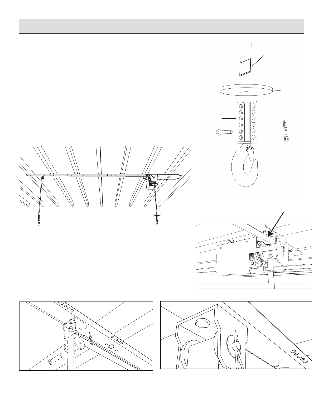
14
STRAP HOLE
STOPPER
PLATE
HEIGHT
ADJUSTMENT
BRACKET
PIN
COTTER PIN
HOOK
Installation (continued)
7 Install straps
□Place the straps coming out of the rectangular opening closest to the spacer
channel bar (g. D) over the top of the pulley at the end of the spacer channel
pulley bar. (g. E)
□Once the strap has been placed over the pulley reinstall the pulley to its original
position, insert the clevis pin and refasten the cotter pin. (g. F)
□Place strap from motor side (g. C) through stopper plate and attach height
adjustment bracket using the supplied cotter pin (g. B).
□Repeat step for pulley side without the stopper plate (g. A).
□Plug in the motor hoist (B) to the nearest 110 volt power outlet.
□Use the hand control switch and safely lower the straps until approximately 9 feet
of cable is hanging down.
A B
C
THE STRAP THAT GOES ACROSS TO THE
SPACER BAR NEEDS TO PASS THROUGH THE
CUT OUT SECTION OF THE MOUNTING PLATE.
D
EF

X 2
Installation (continued)
8 Install the hand control switch holder hook
□Secure the hand control switch holder (H) to a convenient location on the closest appropriate wall using the power cord cable
clamps (J) and screws (W).
□If your cables are too long, use the supplied cable ties to coil them close to the motor for a clean nish.
15 PROSLAT.COM
Please contact 1-888-801-1801 for further assistance.
TIP: IT IS SUGGESTED YOU INSTALL YOUR
CONTROLLER HOLDER FIRST AND RUN YOUR
WIRE BACK TO THE MOTOR. THIS WAY YOUR
EXCESS CABLE WILL BE UP AT THE MOTOR. USE
THE SUPPLIED CLIPS TO ATTACH TO THE WALL.

16
AB
CD
Installation (continued)
9 Assemble the hook bar
□Assemble the three middle pieces of the hook bar by lining up the spring clips from the hook bar center (E) to the holes of the hook bar
connectors (F). (g. A)
□Slide hooks (M) onto the assembled piece. (g. B & C)
□Attach each hook bar end (G) to the assembled middle section by lining up the slotted holes from the hook bar end to the holes of the
hook bar connectors. (g. D)
□Once all of your bars are connected, attach the height adjustment bracket (I) by sliding the hook into the two large holes on the left and
right side of the bar facing inward.

Installation (continued)
10
Level
□The height adjustment bracket (I) is adjustable to make your straps and bars perfectly level lower your straps to eye level and adjust
the pin in the height adjustment bracket (I) to the desired hole to make your straps level.
NOT LEVEL
□If your bar is not level, use the strap adjustment bracket that is located by the hook.
TO ADJUST, REMOVE THE COTTER
PIN ON THE HIGHEST SIDE AND
REINSTALL AT THE HIGHER HOLE.
17 PROSLAT.COM
Please contact 1-888-801-1801 for further assistance.

18
Installation (continued)
11
Using the key lock feature
□To prevent unauthorized use the Garage Gator 68221 is equipped with a key lock feature.
□When the key is turned to the “OFF” position or removed from the hand control switch the unit will not function until the key is
reinserted and turned to the “ON” position.
12
Test the unit
□Press and hold the rocker switch on the hand control to raise and lower the hook bar. When the hook bar reaches the uppermost travel
point the stopper plate above the cable hook will trigger the limit switch ceasing upward movement.

Contact information
Solutions Murales Proslat inc.
225, boul. Industriel
Chateauguay, (Quebec)
J6J 4Z2, Canada
1 888 801-1801
Maintenance
□Check to be sure the motor is properly attached to its
mounting plate. Make sure the bolts are tight.
□Periodically check the condition of the electrical cords, plugs
and controls.
□Periodically check cables for slippage or excessive wear.
Specications
□Model: 68221
□Load capacity: 220 lb
□Lifting Height: 120 in.
□Lifting speed: 30 ft./min
□Strap width: 32 mm
□Voltage: 120 V / 60 HZ / 4.5 amps
□Motor: 3 /10 HP
TO RAISE OR LOWER THE HOOK BAR:
□Do not stand under the lift
□Turn the key in the hand control switch to the “ON” position.
□Press and hold the rocker switch in the direction you want the
hook bar to travel.
□Release the switch when the desired location is reached.
□Operator must let the motor stop for 8 minutes after
continuously working for 2 minutes.
TO LOAD THE HOOK BAR:
□Lower the hook bar to a comfortable height.
□Evenly distribute the weight of articles stored.
□Do not overload the hook bar — maximum capacity is
220 pounds.
□Be sure items are secured before raising the hook bar.
□**Make sure load is secure before lifting.
EXAMPLES OF ITEMS THAT
CAN BE STORED:
Bikes
□Loop one piece of the bike cable through the rim of the front
tire then connect the clip to the oblong ring attached to the
hook bar.
□Loop the second piece of the bike cable through the rim of the
back tire then connect the clip to the oblong ring attached to
the hook bar.
□Hang bicycles by using bike hook. Hook red part around neck
of seat on bicycle as seat is resting on top of bike bar.
Golf Bags
□Golf bags should be hung by the carrying handle — NOT the
shoulder strap.
Canoe/Kayak
□Capacity on hook bar must not exceed 220 lb
□Canoe/kayak straps sold separately
Spare Tires
□Canoe/kayak straps sold separately
Operating instructions
19 PROSLAT.COM
Please contact 1-888-801-1801 for further assistance.

Watch our installation video at proslat.com/pages/instructions
This is the best way to follow and understand the installation process
ASSEMBLY INSTRUCTIONS, USE & CARE GUIDE AND WARRANTY
Questions, problems, missing parts? Before returning to the store, call Proslat/Garage Gator Customer Service
1-888-GATOR-08 8 a.m. – 5 p.m., EST, Monday – Friday / [email protected]
PROSLAT.COM
Table of contents
Other Proslat Lifting System manuals


Popular Lifting System manuals by other brands


Braun
Braun NL501 Series Service manual
 operating instructions")
WOOD'S POWR-GRIP
WOOD'S POWR-GRIP P11104DC(3) operating instructions

Vestil
Vestil D-NS-100-LD manual

Future Automation
Future Automation PIC Series installation instructions

WERTHER INTERNATIONAL
WERTHER INTERNATIONAL 442 LP manual

Beta
Beta 3025/PF Instructions for use

Hinowa
Hinowa LIGHTLIFT 1775 PERFORMANCE Quick instructions

Habegger
Habegger HIT-TRAC 8E Original user guide

Draper
Draper Micro projector lift Installation & operating instruction

Ingersoll-Rand
Ingersoll-Rand ARO RM072S Series Operator's manual

morse
morse 525M-T Operator's manual

Fenix
Fenix AT-04B instructions