Nautilus Hyosung MX5300CE User manual

Service Manual
MX5300CE System
V01.00.03 (2013.05.30)
© Nautilus Hyosung, Inc. All Rights Reserved.

© Nautilus Hyosung, Inc. AllRightsReserved. I
Revision History
Service Manual - MX5300CE System
No. Version Date Description of Change Chapter
1 V01.00.00 2010/03 Preliminary version All
2 V01.00.01 2013/04/09 New Publication All
3 V01.00.02 2013/05/20 Add the "Safe Unit". Chapter 9
4 V01.00.03 2013/05/30 Delete “Functional Description”. Chapter 5
Add the “Précautions pour la sécurité (French)” Chapter 1
© Nautilus Hyosung All Rights Reserved.
The content of this specification is protected by copyright laws.
2013. 05. 30. 4rd Release

II © Nautilus Hyosung, Inc. All Rights Reserved.
Contents
Chapter1. Preface
Purpose ························································································································································ 1-1
Audience ······················································································································································ 1-1
Supported Information ······························································································································· 1-1
What is in This Manual ·······························································································································1-1
Conventions··················································································································································· 1-2
Abbreviations of ATM····································································································································· 1-2
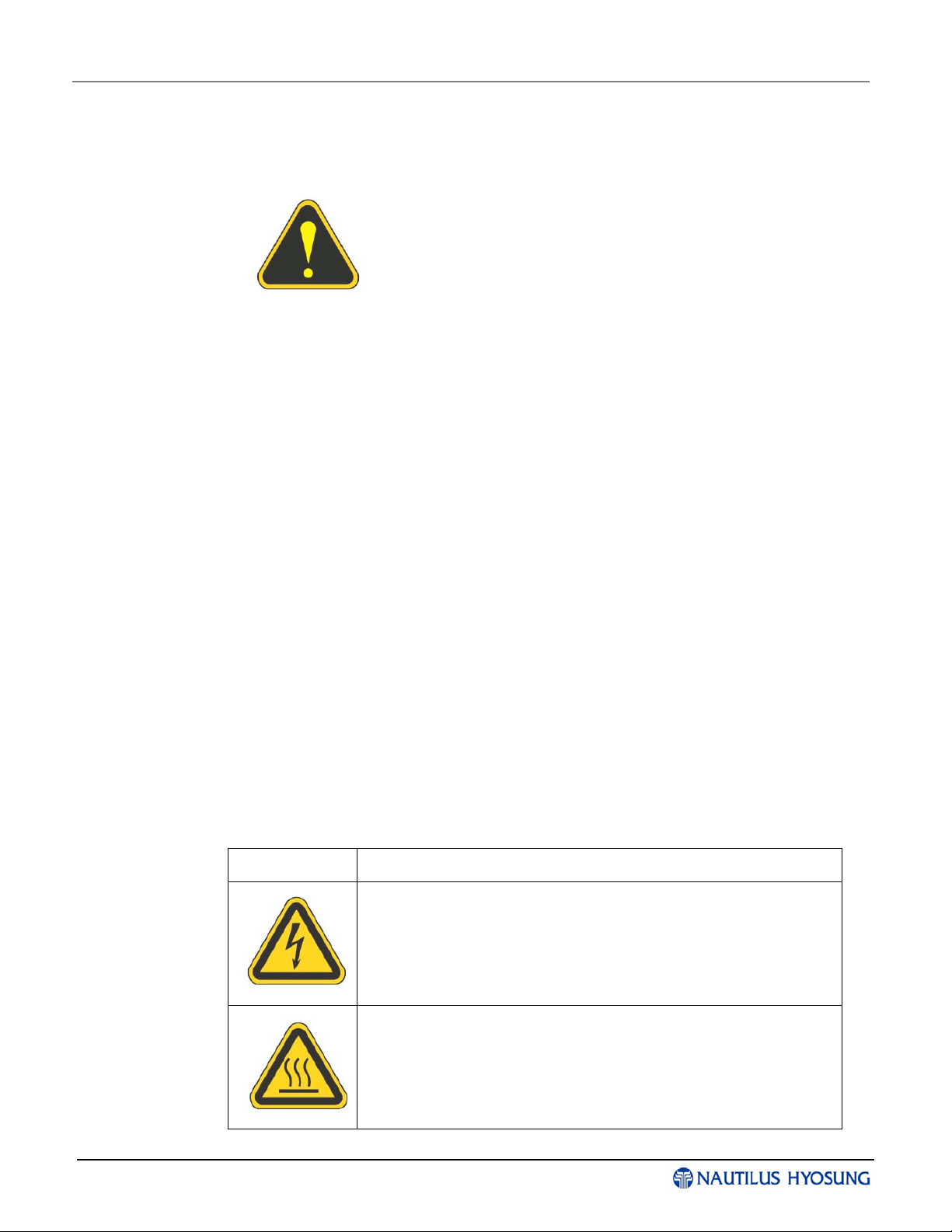
Safety Precautions ········································································································································ 1-4
Précautions pour la sécurité (French)··········································································································· 1-6
Related Documents······································································································································· 1-8
Overview························································································································································ 1-9
Basic Features············································································································································· 1-10
Chapter2. System Configuration
About the MoniMax 5300CE ························································································································· 2-1
External Appearance····································································································································· 2-2
Hardware Configuration································································································································· 2-3
Chapter3. User Handling Unit
Overview ······················································································································································ 3-1
Appearance (Backside)································································································································· 3-1
Monitor··························································································································································· 3-2
Encryption PIN Pad······································································································································3-11
Boards ·························································································································································3-14
Inverter Board·············································································································································· 3-21
Function Key················································································································································ 3-25
Chapter4. Control Electronics
Appearance··················································································································································· 4-1
Disassembly/ Assembly Diagram·················································································································· 4-2
Mother Board Specifications·························································································································· 4-5
Cabling·························································································································································4-16
Chapter5. Power Supply
Overview ······················································································································································ 5-1
Appearance··················································································································································· 5-1
Block Diagram ··············································································································································· 5-2
Disassembly Procedure································································································································· 5-3
Troubleshooting············································································································································· 5-8
Chapter6. Safe Unit
Cencon System S2000·································································································································· 6-1
ELECTRONIC COMBINATION LOCK ·········································································································· 6-4
Chapter7. Receipt Printer
Receipt Printer : K-SPR1 Type ( 728656-10)································································································ 7-1
Option A. Receipt Printer : K-SPR1E Type (70200000-35)········································································· 7-20

© Nautilus Hyosung, Inc. All Rights Reserved. III
Chapter8. CDU (Cash Dispenser Unit)
Appearance/Functional Diagram···················································································································8-1
Unit Block Diagram········································································································································8-6
Module and Sensor Replacement·················································································································8-7
Setting Specifications ··································································································································8-25
Cable Connection Diagram ·························································································································8-26
Adjustment Standard···································································································································8-27
Oiling Standard············································································································································8-30
Interface Specifications································································································································8-33
Required Tools·············································································································································8-34
Chapter9. Safe Unit
How to Open the Safe Door ·························································································································· 9-1
How to Set the new password·······················································································································9-2
Chapter10. Magnetic Card Unit
External Appearance/ Functional Diagram··································································································10-1
Unit Block Diagram······································································································································10-5
Cable Connection Diagram ·························································································································10-6
Interface Specifications································································································································10-7
Repair and Maintenance ····························································································································· 10-9

© Nautilus Hyosung, Inc. All Rights Reserved. Chapter1-I
Chapter 1
Preface
Contents
Purpose ............................................................................................................................................................... 1-1
Audience.............................................................................................................................................................. 1-1
Supported Information ......................................................................................................................................... 1-1
What is in This Manual ........................................................................................................................................ 1-1
Conventions......................................................................................................................................................... 1-2
Abbreviations of ATM........................................................................................................................................... 1-2
Safety Precautions............................................................................................................................................... 1-4
Précautions pour la sécurité (French) ................................................................................................................. 1-6
Related Documents ............................................................................................................................................. 1-8
Overview.............................................................................................................................................................. 1-9
Basic Features................................................................................................................................................... 1-10

ServiceManual Chapter1.Preface
© Nautilus Hyosung, Inc. AllRightsReserved. 1-1
Purpose
▶This manual is produced to provide the MX5300CE maintenance guide for field
technician.
Audience
▶This manual is for persons related to maintenance MX5300CE in branches of banks,
such as field technician and repair center engineer, to work efficiently and conveniently.
Supported Information
▶If any question or error occurs while maintenance MX5300CE in compliance with this
manual, please contact maintenance staffs of Nautilus Hyosung.
For the contact of maintenance staffs of Nautilus Hyosung, see the E-mail addresses
and telephone numbers provided separately.
What is in This Manual
▶This manual contains all information needed for normal operational use.
This manual contains Unit Specifications, Opening & Closing Procedures, Operator
Functions (Supervisor Screen), Error Recovery and etc.
Some of the information in this manual may be subsequently updated by the bank’s
needs or the improvement by Nautilus Hyosung.

Chapter1. Preface Service Manual
1-2 © Nautilus Hyosung, Inc. All Rights Reserved.
Conventions
▶Terminologies
In this document the terminology listed below is used as follows:
▪Customer and consumer refer to any person who transacts business through the
ATM.
▪Device and unit refer to the standard and optional ATM equipment, such as monitor,
card reader, printer and dispenser.
▪Fascia refers to the entire front portion of the unit, including the portion where the
customer transacts business.
▪Module refers to a plug-in device that can be serviced or replaced.
▪Note(s) and bill(s) refer to the individual documents loaded into and dispensed from
the dispenser.
▪Servicing and maintenance refer to the supervisor, operator and technician’s tasks
performed to keep the ATM operational.
▪Screen refers to the text appearing on the customer display.
Abbreviations of ATM
▶In this document the abbreviations listed below is used as follows:
# Abbreviations Description
1 AD board Analog to Digital conversion Board
2 ADA The American Disabilities Act
3 AP Application Program
4 Assy Assembly
5 BATT S/W Battery Switch
6 CAM Camera Unit
7 CDU Cash Dispenser Unit
8 CE Control Electronics
9 Earphone Jack Voice Converter for Visually Disabled Persons (ADA)
10 EMV Europay, Mastercard, Visa
11 EP Elementary Program
12 EPP Encryption PIN Pad
13 H/W Hardware
14 I/F Interface
15 ISO International Standard Organization
16 JPR Journal Printer

ServiceManual Chapter1.Preface
© Nautilus Hyosung, Inc. AllRightsReserved. 1-3
# Abbreviations Description
17 LCD Liquid Crystal Display
18 MCU Magnetic Card Unit
19 OPL Operation Panel for Customers to Operate
20 OSD board On Screen Display Board
21 P/S Power Supply
22 PIN Personal Identification Number
23 PNC Panel Control Board
24 PTR Printer (mainly Receipt Printer)
25 S/W Switch
26 SIU Sensor and Indications Unit
27 SP Service Provider
28 SPR Slip Printer (Receipt Printer)
29 TTU Text Terminal Unit (OPL or SPL)
30 VFD Vacuum Fluorescent Display

Chapter1. Preface Service Manual
1-4 © Nautilus Hyosung, Inc. All Rights Reserved.
Safety Precautions
▶Common Safety Precaution
Precautions outlined this manual provide information on safe
and proper handling of the product. Non-compliance of the
precautions may result in injury or damage to the product.
This precaution symbol with sample term tells you safety
warnings during equipment handlings.
▶Please read the following instructions before operating equipment.
▪Operate equipment in the order outlined in this manual.
▪Follow precautions indicated in this manual, as well as the equipment itself.
Failure to properly address these precautions may lead to injury or damage to the
product.
▪Avoid operations not addressed in this manual.
▪If you cannot remedy system problems using the methods outlined in this manual,
please refer to contact information listed in the manual.
▪Any change or modifications in construction of this device which are not expressly
approved by the party responsible for compliance could void the user’s authority to
operate the equipment.
<Note!>
This equipment has been tested and found to comply with the limits for a Class A
digital device, pursuant to part 15 of the FCC Rules. These limits are designed to
provide reasonable protection against harmful interference when the equipment is
operated in a commercial environment. This equipment generates, uses, and can
radiate radio frequency energy and, if not installed and used in accordance with the
instruction manual, may cause harmful interference to radio communications.
Operation of this equipment in a residential area is likely to cause harmful interference
in which case the user will be required to correct the interference at his own expense.
▶Description of Precaution Symbols
Symbol Description
Electrical Shock Warning
▪Do not remove cover. Only a maintenance engineer is allowed to
open the cover.
▪Do not touch. You may receive electric shock.
▪Make sure to turn off the power when servicing the equipment.
High Temperature Warning
▪Do not touch the equipment when it is running.
▪The equipment can get extremely hot and may cause a burn.
▪Make sure to close the cover before running the equipment.

ServiceManual Chapter1.Preface
© Nautilus Hyosung, Inc. AllRightsReserved. 1-5
Symbol Description
Use Precaution when Moving
▪The equipment is heavy. Make sure at least 2 people lift or move
the equipment.
▪Do not attempt to move the equipment alone. You may be injured
from dropping the heavy equipment.
Fire Hazard
▪Place the equipment in an area away from any combustible
materials.
▪The equipment may catch on fire from overheating or short circuit
of the power supply unit.
Disassembly Warnings
▪Do not disassemble or modify the equipment unless you are a
certified engineer.
▪Contact the service center for maintenance, adjustments and
repairs.
▪Improper disassembly may cause fire or electrical shock.
Collapse Precautions
▪Do not place the equipment where the floor cannot sustain the
weight of the equipment, or on slanted or unstable surface.
▪Equipment may fall and cause injury or damage.
Unplug the Equipment
▪Stop using the equipment immediately if it smokes, emits an
unusual smell, makes abnormal sounds, or if liquids or other
foreign materials enter the equipment.
▪If the above-mentioned abnormalities occur, immediately turn off
the power, unplug the equipment and contact the service center.
▪If you ignore these symptoms, the equipment may catch on fire or
cause electric shock.
<CAUTION>
1.TOREDUCETHERISKOFFIRE,USEONLYNo.26AWGORLARGER
TELECOMMUNICATIONLINECORD
2. RISK OF EXPLOSION IF BATTERY IS REPLACED BY AN INCORRECT
TYPE. DISPOSED OF USED BATTERIES ACCORDING TO THE INSTRUCTIONS
3.FORPLUGGABLE EQUIPMENT, THE SOCKET-OUTLET SHALL BE INSTALLED
NEAR THE EQUIPMENT AN SHALL BE EASILY ACCESSIBLE
4. THE EQUIPMENT IS TO BE SECURED TO THE BUILDING STRUCTURE BEFORE
OPERATION

Chapter1. Preface Service Manual
1-6 © Nautilus Hyosung, Inc. All Rights Reserved.
Précautions pour la sécurité (French)
►Précaution générale pour la sécurité
Précautions décrits de ce manuel fournissent des informations
sur une manipulation sûre et appropriée du produit. Le non-
respect des précautions peut causer des blessures ou
endommager le produit.
Ce symbole de précaution avec le terme d’example vous
indique des consignes de sécurité lors de la manipulation de
l'équipement.
►Veuillez lire des instructions suivantes avant d'utiliser l'équipement
▪Fonctionner l'équipement dans l'ordre indiqué dans ce manuel.
▪Suivre les précautions indiquées dans ce manuel, ainsi que l'équipement lui-même.
Le défaut de traiter correctement de ces précautions peut entraîner des blessures ou
endommager le produit.
▪Évitez des opérations non traitées dans ce manuel.
▪Si vous ne pouvez pas résoudre des problèmes du système en utilisant des méthodes
décrites dans ce manuel, veuillez se référer aux informations de contact figurant dans
le manuel, s’il vous plaît.
▪Certain changement ou des modifications dans la construction de ce dispositif qui ne
sont pas expressément approuvés par la partie responsable de la conformité
pourraient annuler l'autorité de l'utilisateur de faire fonctionner l'équipement.
<REMAQUE!>
Cet équipement a été testé et fondé pour se conformer aux limites pour un équipement
numérique de classe A, conformément à la partie 15 des règles FCC. Ces limites sont
conçues pour fournir une protection raisonnable contre des interférences nuisibles
lorsque l'équipement est utilisé dans un environnement commercial. Cet équipement
génère, utilise et peut émettre des fréquences radios et, s'il n'est pas installé et utilisé
conformément aux instructions de ce manuel, peut causer des interférences nuisibles
aux communications radios.
Le fonctionnement de cet équipement dans une zone résidentielle est susceptible de
provoquer des interférences nuisibles dans le cas, l'utilisateur devra corriger ces
interférences à ses propres frais.
►Description des symboles de précaution
Symbole Description
Choc électrique
• Ne pas retirer le couvercle. Seul le technicien d'entretien est
autorisé à ouvrir le couvercle.
• Ne pas toucher. Vous pouvez avoir un choc électrique.
• Assurez-vous d'éteindre l'appareil lors de l'entretien de
l'équipement.

ServiceManual Chapter1.Preface
© Nautilus Hyosung, Inc. AllRightsReserved. 1-7
À haute temperature
• Ne pas toucher l’équipement quand il est en marche.
• L’équipement peut devenir extrêmement chaud et peut
provoquer une brûlure.
• Assurez-vous de fermer le couvercle avant de lancer
l'équipement.
Soyez prudent lors du déplacement
• L'équipement est lourd. Assurez-vous d'au moins 2
personnes pour soulever ou déplacer l'équipement
• N'essayez pas de déplacer l’équipement seul. Vous pouvez
être blessés par la chute de l'équipement lourd.
Risque d'incendie
• Placer l’équipement dans une zone éloignée de tous les
matériaux combustibles.
• L'équipement peut s'enflammer de surchauffe ou de court-
circuit de l'unité d'alimentation.
Démontage
• Ne pas démonter ou de modifier l'équipement, sauf si vous
êtes ingénieur certifié.
• Contacter le centre de service pour l'entretien, le réglage et
la réparation.
• Le mauvais démontage peut provoquer un incendie ou un
choc électrique.
Tomber
• Ne pas placer l'équipement dont le sol ne peut pas supporter
le poids de l'équipement, ou sur une surface inclinée ou
instable.
• L'équipement peut tomber et provoquer des blessures ou
des dommages.
Débrancher l'équipement
• Cessez d'utiliser l’équipement immédiatement si il fume,
émet une odeur inhabituelle, fait des bruits anormaux ou si
des liquides ou d'autres matériaux étrangers dans
l'équipement.
• Si les anomalies mentionnées ci-dessus se produisent,
éteignez immédiatement la puissance, débranchez l'appareil
et contactez le centre de service.
• Si vous ignorez ces symptômes, l’équipement peut prendre
feu ou provoquer un choc électrique.
AVERTISSEMENT :
1.POURRÉDUIRE LES RISQUES D'INCENDIE, UTILISEZ UNIQUEMENT AWG n ° 26
OU LA LIGNES DE TELECOMMUNICATION PLUS GROSSE
2. RISQUE D'EXPLOSION SI LA BATTERIE EST REMPLACEE PAR UN TYPE
INCORRECT. DISPOSER POUR UTILISATION DES BATTRIES SELON LES
INSTRUCTIONS
3.POURLESAPPAREILS RACCORDES, LA PRISE DOIT ETRE INSTALLEE PRES
D’EQUIPEMENT POUR ÊTRE FACILEMENT ACCESSIBLE
4. L’EQUIPEMENT DOIT ETRE SECURISE A LA STRUCTURE DU BATIMENT AVANT
D'UTILISER

Chapter1. Preface Service Manual
1-8 © Nautilus Hyosung, Inc. All Rights Reserved.
Related Documents
▶The related documents are listed as follows. If needed, please contact staffs of our
technical support team and maintenance team.
▪Operator Manual
▪Operator Function Manual
▪Installation Manual
▪Error Code List
For the contact of maintenance staffs of Nautilus Hyosung, see the E-mail addresses
and telephone numbers provided separately.

ServiceManual Chapter1.Preface
© Nautilus Hyosung, Inc. AllRightsReserved. 1-9
Overview
▶Model MoniMax 5300CE ATM machine is the most up-to-date system to perfectly
meet various customers’ needs in your site. This ATM is designed to satisfy
customers’ demands of withdrawal, balance inquiry and transfer funds for individuals
with a compact size to fit in virtually any place. This machine is connected to your
network to dispense cash, transfer funds and inquiry balance through the insertion of
a customer’s card. Model MoniMax 5300CE ATM is easy to use, easy to be service
and is able to support customer’s demands perfectly.

Chapter1. Preface Service Manual
1-10 © Nautilus Hyosung, Inc. All Rights Reserved.
Basic Features
▶Important features of the model MX5300CE machine is highlighted in the following list:
Main Controller
CPU PXA270 520MHz
Memory
SDRAM 64MB (32MB * 2EA)
Flash Memory 64MB (32MB * 2EA)
NV-RAM 512KB (16bit)
Operating System Windows CE
Serial Ports 7 Ports
USB Ports 2 Ports 1 Host, 1 Client
Modem 56Kbps Dial Up MODEM
LAN TCP/IP
10/100Mbps
(On-Board)
Customer Display
Display Type 15.1” TFT LCD 1024 x 768
Brightness 300 cd/m²
Privacy Filter - Option
(15.1” Filter)
Guide Light Flicker SPR/ MCR Flicker High Bright LED
PIN Light PIN PAD/CDU Light High Bright LED
Sound Speaker /
Earphone Jack ADA Support
Customer Input Method
Pin-Pad Metal Key Cap EPP -
Function Key 4X2 (with NDC style)
Option
(DDC style function
key)
Cash Dispenser
Dispense Type Spray Transaction -
Sutter type Manual Shutter
with Window -
Denomination Dollar User Define
Maximum Dispense 40 Notes/1transaction -
Number of cassettes 1~4 Cassette
Cassette Capacity 2,000 notes / 1 cassettes (US Dollar Brand
New)
Reject Type Note by Note Reject
(200 bills Max) Reject BIN
Card Reader
Type Dip Type

ServiceManual Chapter1.Preface
© Nautilus Hyosung, Inc. AllRightsReserved. 1-11
Magnetic Stripe ISO 1, 2 Read
Receipt Printer
Printing Type Thermal Line Printing
Paper
Specification
Type Thermal Roll Paper
Inside heat sensing
Method
Width Max. 80mm [3.15inch]
Outer Diameter Max. 180Φ
Paper Roll Capacity 3,400 Transaction/Roll
375m (110mm
[4.33inch] /
1transaction)
Dependent on the
user specifications
Black Mark Paper Support Yes
Paper Setting Method Semi-Automatic
Journal Printer
Journal Printer Electronic Journal
Safety
Safety UL 291 Business hour Option
(UL291 Level-1)
Locking device Dial Lock
Electronic Lock &
Cencon Lock
Option
Additional Function
Audio guidance Supported Speaker
ADA Audio guidance Supported Ear Phone Jack

© Nautilus Hyosung, Inc. AllRightsReserved. Chapter2-I
Chapter 2
System Configuration
Contents
About the MoniMax 5300CE................................................................................................................................2-1
External Appearance ...........................................................................................................................................2-2
Hardware Configuration .....................................................................................................................................2-3
System Block Diagram.................................................................................................................................2-3

ServiceManual Chapter2.SystemConfiguration
© Nautilus Hyosung, Inc. AllRightsReserved. 2-1
About the MoniMax 5300CE
▶Model MoniMax 5300CEATM machine is the most up-to-date system to perfectly meet
various customers’ needs in your site. This ATM is designed to satisfy customers’
demands of withdrawal, balance inquiry and transfer funds for individuals with a
compact size to fit in virtually any place. This machine is connected to your network to
dispense cash, transfer funds and inquiry balance through the insertion of a customer’s
card. Model MoniMax 5300CEATM is easy to use, easy to be service and is able to
support customer’s demands perfectly.

Chapter2. System Configuration Service Manual
2-2 © Nautilus Hyosung, Inc. All Rights Reserved.
External Appearance
▶Dimensions of MoniMax 5300CE in which a cash dispenser with 1~3 cassettes is
installed.
<Note!>
All the unit in the dimension is millimeter and the unit in the parenthesis is inch.

ServiceManual Chapter2.SystemConfiguration
© Nautilus Hyosung, Inc. AllRightsReserved. 2-3
Hardware Configuration
System Block Diagram
▶The system block diagram of 5300 CE
Other manuals for MX5300CE
2
Table of contents
Other Nautilus Hyosung Cash Register manuals