Nauto Nauto Device User manual

Installation Guide
Nauto Device & Mark Button
US Installation Guide
May 2019

© Nauto 2019. All Rights Reserved. 2
Table of Contents
Overview.........................................................................................................3
Installation Tool List.................................................................................5
Nauto Components...................................................................................6
OBD Adapter Reference.........................................................................7
Installation
Power Source Connection.....................................................................8
OBD Connection ......................................................................................10
Power Cable Connection.......................................................................11
Device Registration..................................................................................12
Device Installation ...................................................................................13
Vehicle Information.................................................................................15
Mark Button...............................................................................................16
Image Submission....................................................................................17
Additional Resources................................................................................18

© Nauto 2019. All Rights Reserved. 3
Overview
PURPOSE
The purpose of this document is to provide guidelines
for the installation of the Nauto Device. The installation
guidelines, specications, materials and examples
provided in this document are for information purposes
only, are non-exhaustive, and shall not be relied upon for
the specic installation in any vehicle. This guide is not
intended to replace other regulatory requirements in the
jurisdiction where the Nauto Device is installed or used.
Before starting the Nauto Device installation and
conguring the system, please ensure that you have
read this guide thoroughly. If you have any questions or
concerns regarding the installation of the Nauto Device,
please contact Nauto Support at 1 (888) 628-8690 or

© Nauto 2019. All Rights Reserved. 4
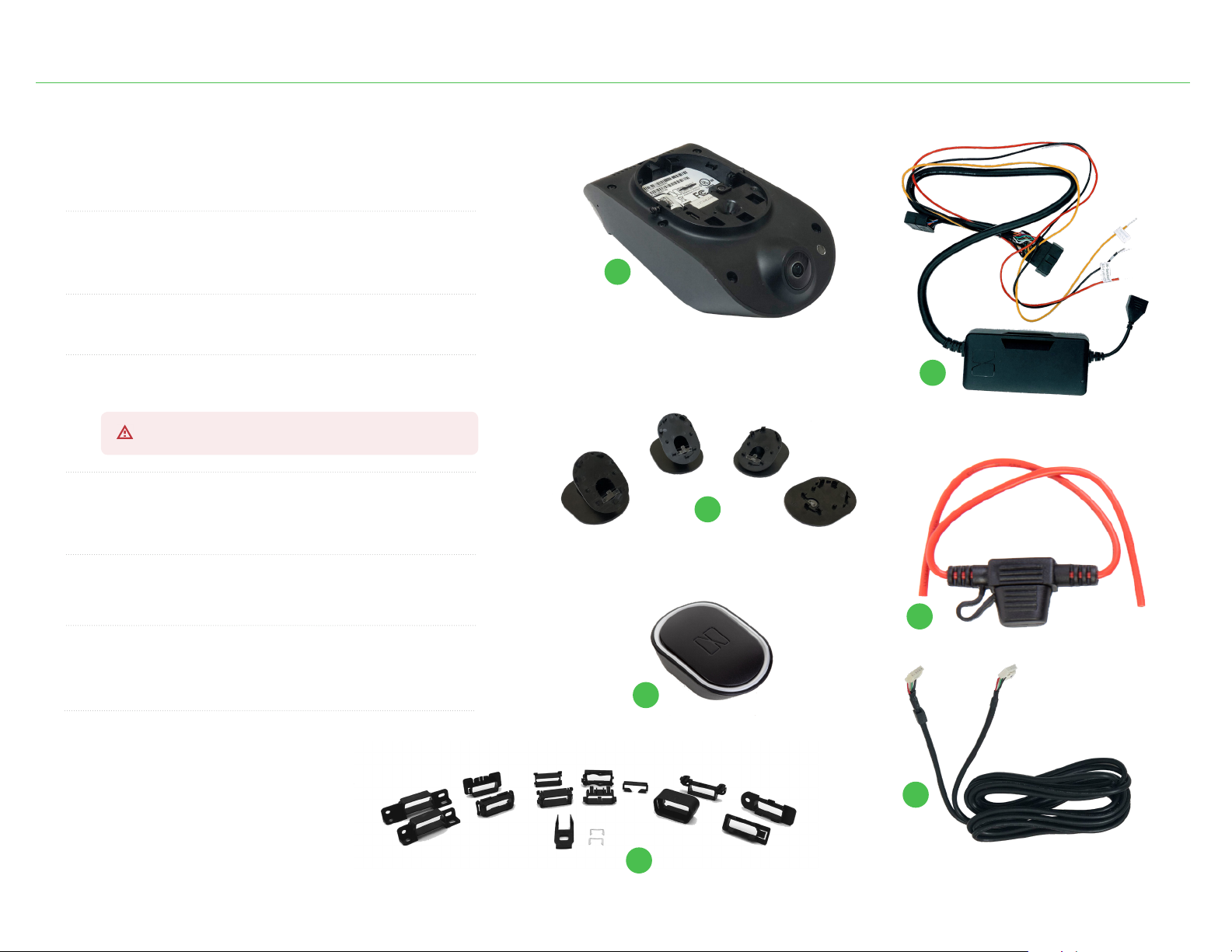
Overview (cont.)
WARNING
This equipment may only be located in a position
where it cannot interfere with the normal and safe
operation of the vehicle, or present a hazard to
the driver, or passengers. When routing all cables
ensure that the insulation does not become worn
or damaged. All cabling must be secured utilizing
industry standard methods.
If you are unsure about the placement or
installation of this equipment, stop work, and
contact your Nauto representative immediately.
Under no circumstances should any part of the
Nauto system be installed inside the engine
compartment area.
This equipment should not be operated in
hazardous environments, or areas that contain
explosive materials or ammable vapors.
This equipment should not be operated in aircraft or
in close proximity to medical equipment.
Unauthorized changes or alterations to the
equipment may invalidate Nauto warranty, and may
also aect the vehicle manufacturers warranty.
DISCLAIMER & SAFETY INFORMATION
Due to ongoing development, information and specications may change at any time without notice. While the
information is believed to be accurate, it may include errors or inaccuracies. Nauto shall not be liable for any use of
the installation guide or information supplied.
The installation of the Nauto Device may adversely aect other vehicle components or safety equipment. Nauto
assumes no responsibility and disclaims any liability for any damage to any vehicle components, safety equipment,
or bodily injury that may arise due to installation or use of Nauto’s products and services.
THE INFORMATION ON THIS INSTALLATION GUIDE IS PROVIDED “AS IS” AND TO THE EXTENT PERMITTED BY LAW,
IS PROVIDED WITHOUT WARRANTY OF ANY KIND, EXPRESS OR IMPLIED, INCLUDING BUT NOT LIMITED TO ANY
IMPLIED WARRANTIES OF MERCHANTABILITY, FITNESS FOR ANY PARTICULAR PURPOSE, OR NON-INFRINGEMENT.
Nauto shall not be liable for any damages, losses, costs or expenses, direct, indirect or incidental, consequential or
special, resulting from the use of this installation guide.
This guide is not written for any specic vehicle since the proper wiring and installation of electronics diers for
each vehicle. Installation should be completed by qualied individuals who are trained to wire electronics such as
the Nauto Device. It is your responsibility to know how to wire in electronics such as the Nauto Device for your
specic vehicle. Improper wiring may cause injury or damage and void the warranty. Any changes or modication
to the Nauto Device not expressly approved by Nauto or the entity responsible for compliance may void any
warranties and your authority to operate the Nauto Device.
This installation guide contains proprietary information that is protected by copyright. All rights are reserved. This
guide may not be copied, reproduced, or translated into another language without Nauto’s prior written consent.

© Nauto 2019. All Rights Reserved. 5
Digital multimeter with sharp leads (or wire piercing leads)
Razor knife
3M Super 33 electrical tape
Wire strippers (self strippers)
Wire crimpers (capable of crimping insulated terminals)
Compact cordless 1/4” impact driver with hex drive
#2 Phillips drill bit
Connection Method Description Recommended Tools
Poke & Wrap Requires splicing into a low voltage wire for a connection. 18 AWG nylon butt connectors (2 or 3)
Posi-Tap Requires posi-tap connectors to tap into wires without cutting or splicing. Proper sized posi-taps
Solder Requires a heated tool to bond wires using a ller metal with low melting point. Soldering iron
Deep ⁄” drive metric sockets (5.5mm and 7-13mm)
T5 Torx driver with handle
Trim panel removal tool
8” or 11” black zip/nylon ties
18 AWG ring terminals
#6 x ⁄” self tapping screws
Installation Tool List
The following tools are recommended to perform installation of the Nauto Device:
The following tools are recommended based on the preferred connection method:

© Nauto 2019. All Rights Reserved. 6
Nauto Components
© Nauto 2019. All Rights Reserved.
Nauto Device
12V Power Supply Adapter
3-wire power supply with OBD Y-cable connector.
Windshield Mounts
Mark Button
Fuse Holder
with 4amp fuse
Power Cable
OBD Adapters
See reference guide on page 7.
1.
2.
3.
4.
5.
6.
7.
Do not dispose of small bag with “MAC address” label.
1
2
3
4
5
6
7

© Nauto 2019. All Rights Reserved. 7
Nauto Components |OBD Adapter Reference
The OBD adapters included with the Nauto Device allows technicians to install the included Y cable. Use the following adapter reference
guide and included instructions to install the Y cable for the Nauto Device.
North American Flange Mount
• Ford
• GM
• Chrysler
North American Extended Flange Mount
• Ford
North American Snap-In Mount
• Chrysler
North American Side & Lock Mount
• Ford
• GM
European Lock Mount
• Mercedes
• BMW
Asian Snap-In
• Toyota
• Hyundai
• Kia
• Ford
European Latch & Snap
• Fiat
• Citroën
• Peugeot
VW Snap-In
• Volkswagen
• Audi
BMW Slide & Lock
• BMW
Ford Round Snap-In
• Ford
Iveco Slide & Lock
• Iveco
Volvo Slide Mount
• Volvo

© Nauto 2019. All Rights Reserved. 8
Installation |Power Source Connection
IMPORTANT
When searching for the correct wires, DO NOT use a test light style
circuit tester. Damage to vehicle computers and vehicle air bag restraint
systems result from the use of a test light causing a short circuit.
One Method for Locating Correct Vehicle Wires
1. Use a multimeter.
2. Set your multimeter to DC voltage.
3. Attach the negative (-) probe to the vehicle chassis ground.
4. Probe the wires you suspect of being the constant and ignition power sources.

© Nauto 2019. All Rights Reserved. 9
Installation |Power Source Connection
1. Find a source of constant +12V DC under the dashboard of the driver side of the car.
a. There are multiple places where this can be found, and locations vary between vehicles. Plan your installation according to your needs. You may nd
specic wiring details by specic vehicle online, such as on The 12 Volt (www.the12volt.com).
b. Ensure that the wire you choose is a constant source of +12V. If you use a multimeter, it should show approximately 12V or better between your source and
chassis ground regardless of the ignition switch position, open or closed doors, on or o lights and other accessories, etc.
2. Using your preferred connection method (poke & wrap, solder, or posi-tap), connect the red wire from the Nauto power supply to the source of +12V. Be sure NOT
to permanently disconnect the 12V source from other circuits in the vehicle and take care to make a strong connection to survive vibration and temperatures.
1. Crimp or solder a ring terminal at the end of the black wire.
2. Connect it directly to a suitable metal spot on the vehicle’s chassis to create a solid ground. One method that may be appropriate is using a self-tapping screw.
The driver’s kick panel under the dashboard is a common grounding area, or any painted metal surface.
1. Locate the wire that you have veried will have ignition (switched) power.
2. If you use a multimeter, probe the yellow wire with the meter lead to check:
a. There should be zero voltage.
b. With the key turned to the “ON” position in the ignition (do not start the vehicle), the wire should show 12 volts DC or more.
c. With the meter lead still probing the wire, start the vehicle. While the starter is cranking, the wire’s voltage should not drop by more than 2 volts.
d. Turn the key to the “OFF” position. The voltage should return to 0.
Constant +12V Power Connection (Nauto Device Red Wire)
Ground Connection (Nauto Device Black Wire)
Switched / Ignition Source (Nauto Device Yellow Wire)
WARNING
Do not plug harness into the Nauto Device while making connections.

© Nauto 2019. All Rights Reserved. 10
Installation |OBD Connection
1. Locate the OBD port within the vehicle, removing vehicle panels as necessary.
2. Gently remove the factory OBD plug from the mount.
3. Select and install the vehicle-appropriate adapter from Nauto’s OBD Adapter Kit (page 6).
4. Using the appropriate adapter, replace the vehicle’s OBD port with the female end of the Nauto Y-cable.
5. If there was an existing device in the vehicle’s OBD port, please reconnect it utilizing the Nauto Y-cable.
6. Plug the male end of the Nauto Y-cable into the vehicle’s OBD port.
7. Zip tie all connections to help ensure plugs will not disconnect.
After making proper power and ground connections, properly secure all loose and extra wiring. A slot built
into the side of the power supply unit can help to secure excess wiring to conceal and secure the wires of the
harness, and trim or bundle up unused wires.
OBD Port Connection

© Nauto 2019. All Rights Reserved. 11
Installation |Power Cable Connection
1. Locate the power end of the power cable, or the end with the small black block
(see image for reference).
2. Leaving 8-10” of the cable exposed, start tucking the cable under the windshield
headliner, starting just above the rearview mirror.
a. The cable should be buried under the headliner so that it will not slide out or
drop from the headliner.
3. Route the cable to the left (driver’s side of the vehicle) and remove the A-pillar
panel to route the cable around, behind, and away from all airbag components
and related vehicle accessories.
4. Pull the door gasket away from the body of the vehicle and run the power cable
into the channel near the pinch weld, but without crossing over the pinch weld,
towards the power supply unit.
5. Connect the white clip into the power supply. Bundle and secure all excess wiring
so it will not interfere with vehicle and driver controls.
6. Mount the power supply unit and bundled wires in a secure location under the
dash of the vehicle with zip ties.
a. The power supply is not waterproof and is intended to be placed inside of the
vehicle. It is not designed to be mounted externally or under the hood of a
vehicle.
Power end of power cable
Power Cable Connection

© Nauto 2019. All Rights Reserved. 12
Installation |Device Registration
from the App Store or Google Play store.
Download the Nauto Installer App
1. Log in. 3. Scan QR Code. 4. Review and conrm
the eet name.
2. Select “New Installation”.
Your username and password
will be provided to you prior to
installation.
The QR code is located on the
device. You may also manually
enter the serial number, which
is located next to the QR code
on the Nauto Device.

© Nauto 2019. All Rights Reserved. 13
Installation |Device Installation
1. Connect the Nauto Device to power.
Insert the power cable end that extends from under the headliner into the
device’s power port. The Nauto Device will now boot up.
2. Check for green lights on the device.
This can take up to one minute. Blue lights will appear on the device rst,
meaning the device is updating software, followed by two green lights.
3. Fit the windshield mount to the back of the Nauto Device.
Do not remove the adhesive backing at this time.
4. Review live images from the Nauto Device.
The Nauto Installer app will show live images from both interior and exterior
cameras. This can take a few minutes.
5. Determine the optimal mounting location.
This is based on the live images and recommended locations (see image on
right).
6. Locate the small screw on the accessible side of the device.
Find this on the exposed side from the rearview mirror. Rotate the T5 screw
clockwise to lock the Nauto Device into place. The other screw will not be
tightened.
7. Clean the desired location using the provided swab.
Dry the area with a clean paper towel, removing all lm and residue.
Device lights guideline
Recommended mounting locations
Live images screen

© Nauto 2019. All Rights Reserved. 14
Installation |Device Installation
8. Mark location for the Nauto Device.
Using the live images as guidance, mark the location for the Nauto Device
on the windshield with tape or marker. For optimal device performance:
a. The forward-facing camera should have a clear view of the front of the
vehicle with no obstructions.
b. The forward-facing camera should not be blocked by window tint or metal
lm found near the rearview mirror. If neither side of the rearview mirror
will produce the desired result, please contact Nauto for additional options.
c. The driver-facing camera should not be easily obstructed by the driver-side
visor.
d. The cameras should not block any sensors or rearview mirror functions.
9. Peel the liner from the adhesive on the windshield mount.
10. Slowly align the device into position.
Check the live images on the app. If your view is properly aligned, gently press
the whole assembly to the windshield.
11. Press and hold.
Press and hold the complete mount to the windshield for at least 15 seconds.
15 seconds is the minimum time for the adhesive to adhere properly. Failure to
properly secure the Nauto Device may cause it to detach from the windshield,
which may lead to catastrophic damage or injury.
12. Verify the mount and Nauto Device are securely attached.
13. Secure all dash panels.
Make sure all cables are secure and out of the driver’s view and movement.
Interior view of Nauto Device
Exterior view of Nauto Device

© Nauto 2019. All Rights Reserved. 15
Installation |Vehicle Information
1. Scan the VIN barcode. 3. Follow prompts.2. Enter the vehicle license
plate and vehicle name.
The barcode is located in the
vehicle.
You will be prompted to
conrm that the device is
powered even when the vehicle
is locked
Conrm with the eet manager
the vehicle identier for
Vehicle Name or ID.

© Nauto 2019. All Rights Reserved. 16
Installation |Mark Button
The Mark Button is a Bluetooth device included with every Nauto
Device. The button is designed to enable drivers to initiate uploads
of video to the cloud.
1. Turn Mark Button ON.
Locate the switch on the back side of the device and toggle it to the “On”
position. It may take up to 30 seconds for the Mark Button to connect to the
Nauto Device via Bluetooth.
2. Conrm connection.
Review the LED light on the Mark Button when pressed. A green LED should
activate upon press.
a. If the LED begins blinking, the Mark Button has not been paired correctly.
You will need to activate manual pairing by pressing both volume buttons
on the Nauto Device for at least 5 seconds, or until the LED lights on the de-
vice ash blue. The Nauto Device will then search for a Mark Button to pair
with. Conrm the connection by pressing the Mark Button until the green
light no longer blinks.
3. Attach the Mark Button.
Using the provided Velcro, attach the Mark Button to the vehicle. Consult the
eet manager for preferred Mark Button placement.
Mark Button
ON switch

© Nauto 2019. All Rights Reserved. 17
Installation |Image Submission
1. Capture installation images.
Follow prompts to capture six (6) images of the vehicle.
a. Odometer
b. Install location
c. Front of car
d. Back of car
e. Driver side
f. Passenger side
2. Complete installation.
Upload images through the Nauto Installer app
to complete installation.
a
d
b
e
c
f

© Nauto 2019. All Rights Reserved. 18
Additional Resources
• the12volt.com (www.the12volt.com)
• Bulldog Security (www.bulldogsecurity.com)
• OBD Port Locater (www.tguide.installernet.com/progressive/progressive.aspx)
• Mitchell 1 (www.mitchell1.com)
• ALLDATA (www.alldata.com)
• Local dealer for vehicle manufacturer
Links to external sites are not under the control of Nauto, inc. Therefore we are not responsible for the content of any linked site.
Nauto, inc. Is providing these links to you only as a convenience, and the inclusion of any link does not imply endorsement by
Nauto, inc. of the linked site.
For any questions or support
888.628.8690
Nauto Support is available Mon - Fri 6AM - 6PM PST.
This manual suits for next models
1
Table of contents
Popular Automobile Accessories manuals by other brands

Volvo
Volvo On Call owner's manual

Bosch
Bosch Flasher-PRO user manual

Siemens
Siemens SICHARGE D 8EM5907-0AA000-1AA7.05 operating instructions

Xpresskit
Xpresskit OptimaX series installation guide

Spotify
Spotify Car Thing quick start guide

Metra Electronics
Metra Electronics 99-9104 installation instructions