manuals.online logo
Brands
  1. Home
  2. •
  3. Brands
  4. •
  5. Navien
  6. •
  7. Boiler
  8. •
  9. Navien NFC-200 User manual

Navien NFC-200 User manual

1
󱂓Unpacking
>
Navien
Condensing
Boiler
Air Vent Condensate
Trap NaviClean
User’s Information Manual, Installation
& Operation Manual Wall Flanges Conversion
Kit
Wall Mounting
Bracket
Tapping
Screws and
Anchors
Pressure
Relief Valve,
Heating
Vent
Termination
Caps
Air Vent
Bushing
(3/4 in to 1/2 in)
Outdoor
Temperature
Sensor and
Cable
System Temperature
Sensor
NFC-175/200
Manifold
System (for
single boilers)
PRV-Air Vent
Adapter
(including a
clip)
Valve Kit Union
Model
NFC-175/200
Quick Installation Guide
STEP 1 Before Installing
Read the Installation & Operation Manual before installing.
This product must be installed and serviced by a licensed plumber,
a licensed gas tter, or a professional service technician. Navien is
not liable for any damages or defects resulting from improper
installation.
WARNING
Follow all local codes and/or the most recent edition of the National Fuel Gas Code (ANSI
Z223.1/NFPA 54) in the USA, or the Natural Gas and Propane Installation Code in Canada
(CAN/CGA B149.1).
Safety
DO NOT install the boiler in areas with excessively high humidity.
Location Requirements
Select the best location on “Choosing an Installation Location” in the Installation &
Operation Manual.
Allowable minimum clearances
Top
Back
Side
Side
Front
Bottom
Clearance Indoor Installation
Top 9 in (229 mm) minimum
Back 0.5 in (13 mm) minimum
Front 4 in (100 mm) minimum
Sides 3 in (76 mm) minimum
Bottom 12 in (300 mm) minimum
STEP 2 Installing
󱂔Checking the Rating Plate
>
This boiler is congured
for Natural Gas from the
factory. If conversion to
Propane Gas is required,
the conversion kit supplied
with the boiler must be
used.
WARNING
·Before connecting the gas supply, determine the gas type and pressure for the boiler by
referring to the rating plate. Use only the same gas type indicated on the rating plate. Using a
dierent gas type will result in abnormal combustion and malfunction of the boiler. Gas
supplies should be connected by a licensed professional only.
·The appliance and its gas connection must be leak tested before placing the appliance in
operation.
·This boiler cannot be converted from natural gas to propane or vice versa without a Navien gas
conversion kit. Do not attempt a eld conversion of this boiler without a Navien gas conversion
kit. Doing so will result in dangerous operating conditions and will void the warranty.
Navien Inc. is not liable for any property damage and/or personal injury resulting from
improper conversions.
󱂕Mounting on the Wall
>
CAUTION
Do not install the boiler on dry walls without proper reinforcement.
Drill in the supplied anchor bolts
after considering where the vent
termination will be located.
1
Lift up the boiler, rest the unit on the hooks
provided on the wall bracket on the wall.
Secure the mounting bracket to the wall
with the tapping screws and anchors.
2
󱂖Removing the Front Cover
>
Unclasp the 4 buckles that x
the cover to the boiler, and then
remove the cover by lifting it
and pulling it outward.
2
󱂗Gas Piping Connections
>
󱂘Water Piping Connections
>
Water Piping Connections
Space
Heating
Supply
Cold Water
Inlet (DHW)
Gas Connection
Hot Water
Outlet (DHW)
Space Heating
Return
Auto Feeder Inlet
(Make-up Water)
Condensate
Outlet
From
System
Expansion Tank
Make-up
Water
Pump
To System
Air Separator
Pressure Relief Valve
Gas Supply Line
Gas Inlet Adapter
Gas
Regulator
Gas supply
Bottom View
The boiler is
recommended
to be the rst
appliance to be
connected to
the gas supply
line.
Drip Rig
The gas meter capacity
must be greater than
the total gas capacity of
connected appliances. Example:
Gas meter
425 CFH ≥Boiler
195 CFH +Furnace
58.8 CFH +Domestic gas stove
63.7CFH
* 1 CFH=1,020 Btuh
1/2" rigid pipe can be used; refer to the sizing tables in the Installation & Operation
Manual for limitations. Avoid using 1/2" corrugated connectors or tubing as noise may
occur.
󱂙Condensate Drain Connection
>
A condensate drain pipe must be connected to the 1/2” condensate trap tting at the
bottom of the unit and water must be poured into the exhaust connection to ll the
condensate trap.
Condensate trap
Floor drain
Water
The end of the 1/2” (NPT) plastic piping should drain into a laundry tub or into a oor
drain.
Note Do not submerge the end of
the pipe in water.
a
b
c
d
Direct to the external drain
To the
Drain via a
neutralizer
External drain
To the laundry tub
To the laundry tub
via a condensate pump
Space Heating System
A pressure relief valve must be installed when installing piping for a heating system.
Install the included 3/4in, maximum 30 psi pressure relief valve on the space heating supply.
An ASME approved HV pressure relief valve for space heating system is supplied with the boiler.
You may install the pressure relief valve on the space heating supply of the Navien Manifold System, or on the top connection along
with the air vent (and an external LWCO, if required).
CAUTION
Do not solder piping directly onto the water connections, as the heat may cause damage to internal components. Use
threaded water connections only.
System Fill Connection
1
2
Pressure Relief Valve
Air Vent
PRV-Air Vent
Adapter
Air Vent
Bushing
Clip
Air Vent
External
LWCO
Pressure
Relief Valve
The Navien NFC boilers have a top connection for an air
vent. An air vent must be installed to purge air from the
boiler system.
To insecure the adapter to the tting, install the
provided clip after inserting the PRV-air vent adapter
into the connection on top of the unit.
When installing the air vent, install the air vent bushing
between the air vent and the top connection.
Before lling the boiler, remove the air vent cap to allow
the system to ll properly. Replace the cap when the
system is full.
Note Prior to connecting piping to the boiler, ush
the entire system to ensure it is free of
sediment, ux, scale, debris or other
impurities that may be harmful to the system
and boiler. During the assembly of the
heating system, it is important to keep the
inside of the piping free of any debris
including construction dust, copper burr,
sand and dirt.
Note Ensure that the vent cap is re-installed and
the vent screws on the system and boiler
pumps are properly tightened before testing
or operating the system.
3
󱂚Venting
>
󱂛Electrical Connections/High Altitude DIP Switch Settings
>
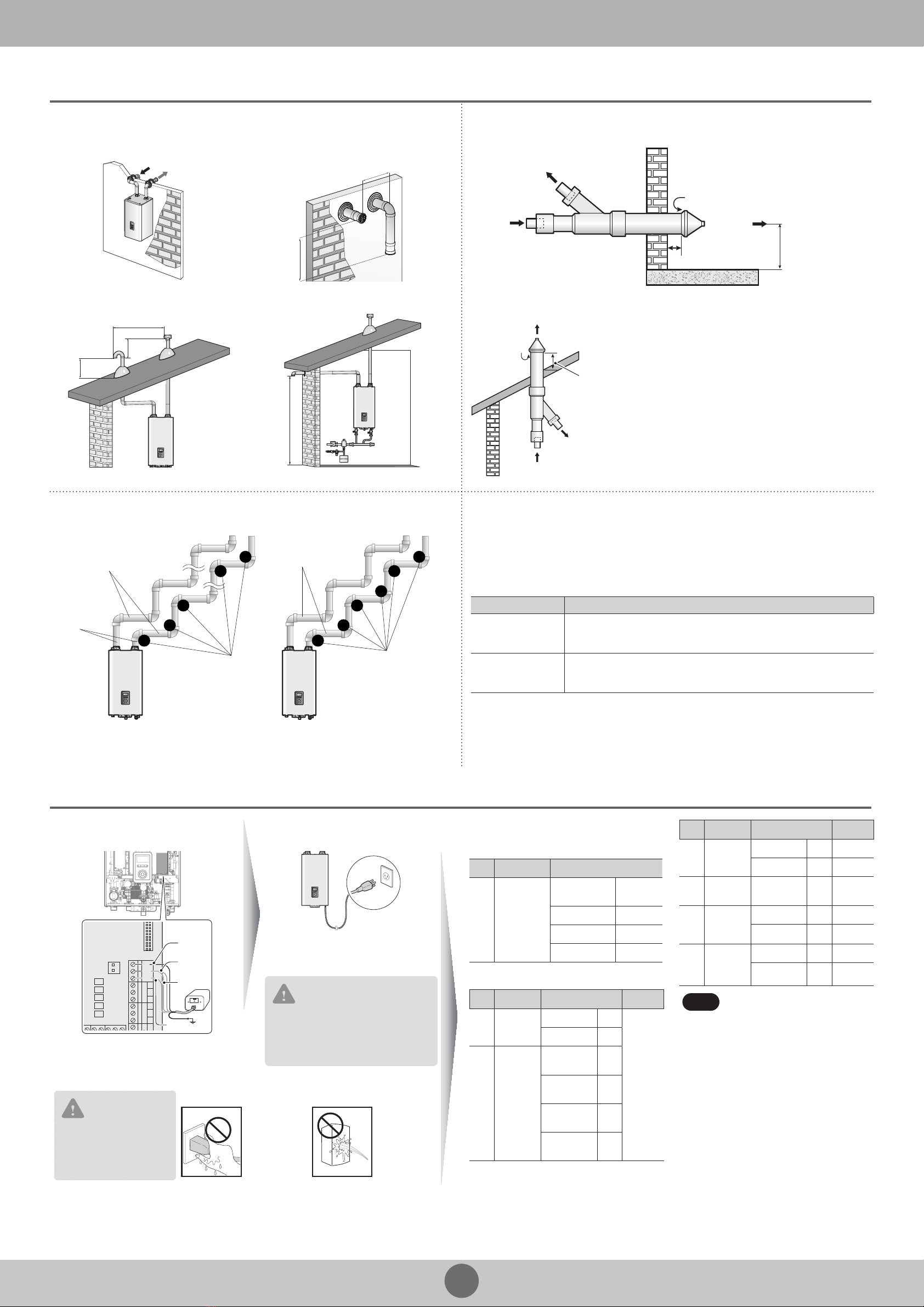
Vent Termination Options
Horizontal vent termination
12" (300 mm) min.
12" (300 mm) min.
Interior view
Intake Air
Exhaust Gas
12" (300 mm) min.
12" (300 mm) min.
Exterior view
Vertical vent termination Sidewall vent termination
Maintain 12”(300mm)
from any obstruction
above, below, left, or right
12" (300 mm) min.
12" (300 mm) min.
36" (900 mm) min.
12" (300mm) min.*
Concentric Vent Termination
Sidewall installation
Combustion Air
Combustion Air
1" (25mm) min.
Maintain 12" (300
mm) min. clearance
above highest
anticipated snow
level or grade,
whichever is greater
Vent
Roof installation
Vent
Vent
Combustion Air
Maintain 12” (300mm) min.
clearance above highest
anticipated snow level or
grade, whichever is greater
(maximum of 24” above roof)
Combustion
Air
Venting Length
3” pipe venting 2” pipe venting
8
1
3
7
2
Maximum Length 150'
Maximum number
of elbows: 8
2-to-3-inch
6
1
3
4
5
2
Maximum number
of elbows: 6
Maximum Length 60'
·90˚ elbow = 5 linear feet of venting
·45˚ elbow= 3 linear feet of venting
·90˚ elbow = 8 linear feet of venting
·45˚ elbow= 4 linear feet of venting
Exhaust Vent Piping Materials
·All Navien boilers are Category IV appliances.
·The venting system should be approved for use with Category IV appliances (typically Type BH
Special Gas Vent approved by UL 1738-S636).
·Venting requirements in the USA and Canada are dierent (see below).
Navien recommended venting materials
Locale Recommended Vent Materials
USA
·PVC/CPVC Schedule 40 or 80 (Solid Core)
·Approved Polypropylene (PP)
·Approved Stainless Steel (SS)
Canada*
·Type BH Special Gas Vent Class IIA (PVC)
·Type BH Special Gas Vent Class IIB (CPVC)
·Type BH Special Gas Vent Class IIC (Polypropylene/Stainless Steel)
* For installation in Canada, eld-supplied plastic vent piping must comply with CAN/CGA B149.1 (latest
edition) and be certied to the Standard For Type BH Gas Venting Systems, ULC-S636. Components of this
listed system must not be interchanged with other vent systems or unlisted pipes or ttings. All plastic
components and specied primers and glues of the certied vent system must be from a single system
manufacturer and must not be intermixed with another system manufacturer’s parts.
The supplied vent connector and vent termination are certied as part of the boiler.
External LWCO Connection
(if required by local codes)
Power Connection
AC24VN
AC24VL
lLWCO
RWC
T/S_Recir.
RWC
W
C
T/S_CH_ZONE1
T/S_ZONE2
Neutral
Live
Live
LWCO
Refer to your local codes to determine if an
LWCO device is required for your system and
ensure that the built-in device meets the
requirements.
120 V AC 60 Hz
Min. 2 Amp current with proper
grounding
CAUTION
Using abnormally high or low AC
voltage may cause abnormal operation,
thereby causing re which reduces the
life expectancy of this product.
CAUTION
Disconnect the power to
the boiler before installing
any wire connections on
the main PCB.
Safety
DO NOT touch
the power
cord with wet
hands.
DO NOT allow
the boiler to be
exposed to
excessive
amounts of
water.
Conrmation of DIP Switch Settings
DIP Switch 1 (6 switch unit)
SW Function Setting
1 & 2 Operation
Status
Normal
Operation 1-OFF, 2-OFF
2-stage MAX 1-ON, 2-OFF
1-stage MIN 1-OFF, 2-ON
1-stage MAX 1-ON, 2-ON
DIP Switch 2 (8 switch unit)
SW Function Setting
Comment
1Gas Type
Natural Gas
1-OFF
Refer to
Table 1
on page
103 in the
Installation
&
Operation
Manual.
Propane Gas
1-ON
2 & 3 High
Altitude
0-1,999 ft
(0-609 m)
2-OFF,
3-OFF
2,000-5,399 ft
(610-1,645 m)
2-ON,
3-OFF
5,400-7,699 ft
(1,646-2,346 m)
2-OFF,
3-ON
7,700-10,100 ft
(2,347-3,078 m)
2-ON,
3-ON
SW Function Setting
Comment
4Well Pump
Used
4-ON
-
Unused
4-OFF
-
5 & 6 Country
US/Canada
5-OFF,
6-OFF
-
7
Space
Heating
Thermostat
Used
7-OFF
-
Unused
7-ON
-
8
Exhaust
Temperature
Control
Used
8-OFF
-
Unused
8-ON
-
Note
·When PCB DIP switch 2 #8 is set to
On, ensure that CPVC,
polypropylene, or stainless steel is
used for exhaust venting.
·This unit may be installed at
elevations up to 10,100 ft (3,078 m)
for use with natural gas and
propane. To use the unit at a specic
altitude, the DIP switches should be
set as described above.
·High Altitude: Above 2,000 ft (610 m),
the unit will de-rate by 3% for each
1,000 ft (305 m) of altitude gain.
·For NG, if you install the unit at
above 5,400 ft (1,646 m), it is
required to change the Gas Orice
for high altitude. Be careful not to
confuse it with the LP Gas Orice.
For detail, refer to page 103 in the
Installation & Operation Manual.
4
STEP 3 After Installing
󱂓Opening All the Valves
>
Gas Valve Space Heating System Valves
Shut-o
valves
Power ON Adjust Temperatures View Basic Information Resetting the Boiler
Space Heating Temperature DHW Temperature
1. In normal operation mode, rotate
the Command dial ( ). The space
heating temperature ( ) is
highlighted on the screen.
2. Rotate the Command dial ( ) to
the right to select the DHW
temperature.
3. Press the Command dial ( ) to
select the indirect DHW
temperature ( ). The highlighted
section will ash.
4. Rotate the Command dial ( ) to
the right or left to increase or
decrease the temperature.
5. Press the Command dial ( ) to
conrm the new temperature.
6. Press the Back button ( ) to
return to normal operation mode,
or rotate the Command dial ( )
to adjust other operation
conditions.
Note DHW temperature higher
than 180°F can cause
scalding.
To turn the boiler on, press the
Power button.
When the power is on, the boiler
automatically enters normal
operation mode, and the boiler’s
operating conditions are displayed
on the screen.
1. In normal operation mode, rotate the
Command dial ( ). The space
heating temperature ( ) is
highlighted on the screen.
2. Press the Command dial ( ) to select
the space heating temperature. The
highlighted section will ash.
3. Rotate the Command dial ( ) to the
right or left to increase or decrease
the temperature.
4. Press the Command dial ( ) to
conrm the new temperature.
5. Press the Back button ( ) to return
to normal operation mode, or rotate
the Command dial ( ) to adjust
other operation conditions.
1. Press the Menu button ( ), and
then select “2. Status
Information”.
2. Rotate the Command dial ( ) to
switch between the information
items.
If an error message appears during
boiler operation, reset the boiler to
resolve the problem. Press the Back
button ( ) on the front panel to
reset the boiler.
Note If resetting does not
solve the problem, refer
to the troubleshooting
section of the User’s
Information Manual or
contact the service
center.
1
Open Closed
2
Open a hot water
faucet. The boiler
should turn on and
the gas in the gas
supply line will be
purged.
3 4
Shut o the manual gas valve. Leave the faucet on until the boiler shuts down
due to a lack of gas supply, and then turn o the
hot water faucet.
Remove the front cover by
loosening the 4 screws.
Loosen the screw indicated in the gure and
connect a manometer to the pressure port.
Reset the manometer to zero before use.
5
Open
Re-open the manual
gas valve and check
for leaks.
Open multiple
xtures that have
high ow rates, such
as bathtub and
shower faucets, to
ramp the boiler up to
its maximum ring
rate.
6
NG: 3.5”–10.5”WC
LP: 8.0”–13.5”WC
Recommended
Gas Pressure Settings:
Check the inlet gas pressure reading on the manometer.
If not,
Gas supply
Adjust the inlet gas pressure with gas regulator.
CAUTION
The boiler cannot function properly without sucient inlet gas pressure. Measuring the inlet gas pressure should be performed by a licensed professional only.
Navien, Inc.
20 Goodyear, Irvine, CA 92618
Tel: 1-800-519-8794, Fax: 1-949-420-0430
www.navien.com
󱂖Installing the Front Cover
>
󱂗Ensure Maximum Water Flow
>
After running the boiler for the rst 10 minutes, turn it o and clean the cold water lter
and the space heating return strainer to remove any trapped debris.
󱂘Final Check
>
A trial run should be performed in accordance with the Installation checklist listed in
the boiler’s Installation & Operation Manual.
󱂔Operating the Boiler
>
󱂕Measuring the Inlet Gas Pressure
>

This manual suits for next models

1

Other Navien Boiler manuals

Navien NFC-250/175H User manual

Navien

Navien NFC-250/175H User manual

Navien NFC-250/175H User manual

Navien

Navien NFC-250/175H User manual

Navien LST-58K User manual

Navien

Navien LST-58K User manual

Navien NFC-175 User manual

Navien

Navien NFC-175 User manual

Navien NFB-175H User manual

Navien

Navien NFB-175H User manual

Navien NCB-24LDWE User manual

Navien

Navien NCB-24LDWE User manual

Navien NCB-150E User manual

Navien

Navien NCB-150E User manual

Navien NCB-180 User manual

Navien

Navien NCB-180 User manual

Navien NHB-055 User manual

Navien

Navien NHB-055 User manual

Navien NCB-180 Guide

Navien

Navien NCB-180 Guide

Navien NHB H Series User manual

Navien

Navien NHB H Series User manual

Navien NFC-250/200H Guide

Navien

Navien NFC-250/200H Guide

Navien NCB-20LHWE User manual

Navien

Navien NCB-20LHWE User manual

Navien NCB-24LSWE User manual

Navien

Navien NCB-24LSWE User manual

Navien CH-180 User manual

Navien

Navien CH-180 User manual

Navien NFB-175H Guide

Navien

Navien NFB-175H Guide

Navien NCB500-2S/37K User manual

Navien

Navien NCB500-2S/37K User manual

Navien NHB-055 User manual

Navien

Navien NHB-055 User manual

Navien NCB700-24L Guide

Navien

Navien NCB700-24L Guide

Navien NCB500-1.5S/37K User manual

Navien

Navien NCB500-1.5S/37K User manual

Navien CH-180 Mounting instructions

Navien

Navien CH-180 Mounting instructions

Navien NCB-700-2S+/42K User manual

Navien

Navien NCB-700-2S+/42K User manual

Navien NFC Series Guide

Navien

Navien NFC Series Guide

Navien LCB700-21RS User manual

Navien

Navien LCB700-21RS User manual

Popular Boiler manuals by other brands

Truma BE 14 operating instructions

Truma

Truma BE 14 operating instructions

Bosch Condens 7000 F Operating instructions for users

Bosch

Bosch Condens 7000 F Operating instructions for users

Astra G-50 Installation and operation manual

Astra

Astra G-50 Installation and operation manual

Daikin D2CND028A1AB installation manual

Daikin

Daikin D2CND028A1AB installation manual

Kiturami KRP-20A user manual

Kiturami

Kiturami KRP-20A user manual

Cleveland KDL Operator's manual

Cleveland

Cleveland KDL Operator's manual

Gorenje TEG 5 O Instructions for use

Gorenje

Gorenje TEG 5 O Instructions for use

Harman PB 105 owner's manual

Harman

Harman PB 105 owner's manual

Coopers of Stortford 9619 instructions

Coopers of Stortford

Coopers of Stortford 9619 instructions

Viessmann VITODENS 333 Service instructions

Viessmann

Viessmann VITODENS 333 Service instructions

Benchmark GB10 Design, installation and servicing instructions

Benchmark

Benchmark GB10 Design, installation and servicing instructions

Metal-Fach SEMAX OPTI 16 operating instructions

Metal-Fach

Metal-Fach SEMAX OPTI 16 operating instructions

Grant EFCON5090MOD User instructions

Grant

Grant EFCON5090MOD User instructions

Ferroli Bluehelix PRO C Instructions for use, installation & maintenance

Ferroli

Ferroli Bluehelix PRO C Instructions for use, installation & maintenance

Reimers HLR15 instruction manual

Reimers

Reimers HLR15 instruction manual

Ferroli Pegasus F3 119 manual

Ferroli

Ferroli Pegasus F3 119 manual

Alarko SERADENS SUPER PLUS SSP 20 Installation and operating instructions

Alarko

Alarko SERADENS SUPER PLUS SSP 20 Installation and operating instructions

Ferroli optima 800 Technical information installation and service instruction

Ferroli

Ferroli optima 800 Technical information installation and service instruction

manuals.online logo
manuals.online logoBrands
  • About & Mission
  • Contact us
  • Privacy Policy
  • Terms and Conditions

Copyright 2025 Manuals.Online. All Rights Reserved.