Navigator Pit Boss PB1230G User manual

ITEM : 172779
MODEL : PB1230G
PART : 10711
IMPORTANT, READ CAREFULLY, RETAIN FOR
FUTURE REFERENCE. MANUAL MUST BE READ
BEFORE OPERATING!
For outdoor and household use only. Not for commercial use.
WARNING Please read the entire manual before installation
and use of this electric, pellet fuel-burning appliance.
Failure to follow these instructions could result in property
damage, bodily injury or even death. Contact local building
or fire officials about restrictions and installation inspection
requirements in your area.
AUSTRALIA AND NEW ZEALAND
GAS SAFETY CERTIFICATION
®
DO NOT REMOVE

2
EN ENGLISH
Parts & Specs......................................................................4
Assembly Preparation......................................................6
Assembly Instructions
Assemble the Grease Tray Support ..........................................6
Mounting the Grease Tray To the Main Barrel ......................6
Installing the Lid Stopper........................................................... 7
Securing Support Plates And Caster Wheels.......................... 7
Securing Support Plates And Wheels ...................................... 7
Securing The Frame Assembly...................................................8
Mounting Main Barrel To The Cart...........................................8
Securing Cart Panel To The Grill ................................................8
Securing The Cart Bars................................................................8
Attaching The Cylinder Wire Retainer .....................................8
Securing The Cylinder Support Bracket...................................9
Attaching The Hose Retainer.....................................................9
Installing The Lid Handle............................................................9
Securing The Front Shelf Brackets............................................9
Installing The Front Shelf ...........................................................9
Installing The Side Shelf .............................................................9
Installing The Grill Cooking Components ............................. 10
Installing Grease Bucket........................................................... 10
Installing The Battery .............................................................. 10
Connecting To A Power Source................................................ 10
COPYRIGHT NOTICE
Copyright 2020. All right reserved. No part of this manual may be
copied, transmitted, transcribed, stored in a retrieval system, in any
form or by any means without expressed written permission of,
Dansons
3411 North 5th Avenue, Suite 500, Phoenix, , 85013
www.pitboss-grills.com
Customer Service in Australia and New Zealand:
Genesis International Corporation Pty Ltd.
1/71 Truganina Road Malaga WA 6090
+61 8 9248 9822
service@genesiscorp.com.au

3
EN
ENGLISH
Part# Description
1Porcelain-Coated Steel Upper Cooking Rack (x2)
2Porcelain-Coated Cast-Iron Cooking Grid (x4)
3Flame Broiler Slider (x1)
4Flame Broiler Main Plate (x1)
5Smoke Adjusting Bar (x1)
6Smoke Adjusting Bar Knob (x1)
7Heat Tent (x3)
8Lid Stopper (x2)
9Lid Handle (x2)
10 Lid Handle Bezel (x4)
11 Main Barrel / Hopper Assembly (x1)
12 Meat Probe (x2)
13 Flame Broiler Adjusting Bar (x1)
14 Side Shelf (x1)
15 Grease Tray Support A (x2)
16 Grease Tray Support B (x2)
17 Grease Tray (x1)
18 Grease Bucket Liner (x1)
19 Grease Bucket (x1)
20 Support Leg for Caster / Back (x1)
21 Support Leg for Caster / Front (x1)
22-1 Left Front Support Leg Trim Piece (x1)
22-2 Left Back Support Leg Trim Piece (x1)
23 Locking Casters (x2)
24 Support Leg / Back (x1)
25 Support Leg / Front (x1)
26 Wheel (x2)
27 Cart Side Panel (x2)
28 Cart Back Panel (x1)
29 Cart Front Panel (x1)
30 Cart Support Girder M (x1)
31 Cart Support Girder L (x1)
Part# Description
32 LP Gas Cylinder Support Bracket (x1)
33 LP Gas Cylinder Wire Retainer (x1)
34 Cart Bar A (x2)
35 Cart Bar B (x1)
36 Front Shelf Bracket /L (x1)
37 Front Shelf Bracket /R (x1)
38 Front Shelf (x1)
39 Cable Clips (x1)
40 Power Cable (x1)
AScrew (x33)
BWasher (x33)
C Locking Washer (x33)
DScrew (x26)
EScrew (x4)
F Wheel Cotter Pin (x2)
G Wheel Washer (x2)
H Wheel Axle Pin (x2)
I AA Battery (x1)
NOTE: Due to ongoing product development, parts are subject to change without notice. Contact
Customer Service if parts are missing when assembling the unit.
220240, 50, 250, 3
Diagram Illustration on next page.
MODEL UNIT ASSEMBLED
(WxHxD)
UNIT
WEIGHT
COOKING AREA TEMP.
RANGE
DIGITAL
FEATURES
1230
1,759mm x 1,195mm x 866mm
/ 69.2" x 47" x 34.1"
92 kg /
202.82 lb
Main Pellet
- 2,580.6 cm / 400 sq. in.
Upper Rack
- 1,489 cm / 230.8 sq. in.
TOTAL
- 4,069.6 cm / 630.8 sq. in.
Main Gas
- 2,580.6 cm / 400 sq. in.
Upper Rack
- 1,489 cm / 230.8 sq. in.
TOTAL
- 4,069.6 cm / 630.8 sq. in. 82-260°C /
180-500°F
Ten temperature
presets, start-up
cycle, electric
igniter
TOTAL GRILL
- 8,139.2 cm / 1,261.6 sq. in.

4
EN ENGLISH
34
33
32
31
29
30
28
27
26
25
24
23
222
221
21
20
19
18
17
16
15
14
13
12
11
10
9
8
7
65
4
3
2
1
39
40
35
36
3738

5
EN
ENGLISH
IMPORTANT: It is advised to read each step entirely before starting assembly on instructions. Do not tighten screws completely
until all screws for that step have been installed. Hardware combination involving a locking washer and washer should be
installed with the locking washer closest to the head of the screw.
1.
Parts Required:
2 x Grease Tray Support A
(#15)
2 x Grease Tray Support B
(#16)
4 x Screw
(#D)
Installation:
• Mount Grease Tray Support A to Grease Tray Support B using four screws.
2.
Parts Required:
1 x Main Barrel / Hopper Assembly
(#11)
1 x Cable Clip
(#39)
1 x Power Cable
(#40)
6 x Screw
(#A)
6 x Washer
(#B)
6 x Locking Washer
(#C)
Installation:
• Place a piece of cardboard on the floor to prevent scratching the unit. Lay the
Main Barrel on it's side, hopper end pointed upward on the cardboard.
• Mount Grease Tray Support to the floor end of the Main Barrel using six
screws, locking washers and washers. Note illustration 2A.
• Place the Cable Clips on the Power Cable. Insert the power cord into a groove
at the bottom of the hopper.
• Secure the wire clip to the hopper using screws pre-installed at the bottom of
the hopper. Note illustration 2B.
1
16
15
2 11
15
Parts are located throughout the shipping carton, including underneath the grill. Inspect the grill, parts, and hardware blister pack after
removing from the protective shipping carton. Discard all packaging materials from inside and outside of the grill before assembly, then
review and inspect all parts by referencing the parts list. If any part is missing or damaged, do not attempt to assemble. Shipping damage
is not covered under warranty. Contact Bunnings Australia or Genesis International Corporation Pty Ltd. for Customer Service.
service@genesiscorp.com.au | +61 8 9248 9822
IMPORTANT: To ease installation and avoid injury, use two people when assembling this appliance.
Tools required for assembly: screwdriver and level.
Tools not included.
2
39
40

6
EN ENGLISH
3.
Parts Required:
2 x Lid Stopper
(#8)
Installation:
• Secure the Lid Stopper onto the top of the Main Barrel using the pre-installed
screw on top of the Main Barrel.
4.
Parts Required:
1 x Support Leg for Caster / Back
(#20)
1 x Support Leg for Caster / Front
(#21)
1 x Left Front Support Leg Trim Piece
(#22-1)
1 x Left Back Support Leg Trim Piece
(#22-2)
1 x Cart Side Panel
(#27)
1 x Cart Support Girder / M
(#30)
2 x Locking Caster
(#23)
4 x Screw
(#A)
4 x Washer
(#B)
4 x Locking Washer
(#C)
10 x Screw
(#D)
Installation:
• Screw Left Front Support Leg Trim Piece to Support Left for Caster /Front.
Screw Left Back Support Leg Trim Piece to Support Left for Caster /Back. Note
illustration 4A.
• Fix Support Leg for Caster /Front and Support Leg for Caster /Back assembled
in previous step with Cart Side Panel connection with screws (#D). Fix the
Cart Support Girder M on the assembled parts in previous step with screws
(#A), locking washers and washers. Note illustration 4B.
5.
Parts Required:
1 x Support Leg / Back
(#24)
1 x Support Leg / Front
(#25)
2 x Wheel
(#26)
1 x Cart Side Panel
(#27)
1 x Cart Support Girder / L
(#31)
4 x Screw
(#A)
4 x Washer
(#B)
4 x Locking Washer
(#C)
4 x Screw
(#D)
2 x Wheel Axle Pin
(#F)
2 x Wheel Washer
(#G)
2 x Wheel Cotter Pin
(#H)
Installation:
• Fix Support Leg/ Back and Support Leg/ Front with cart Side Panel with
screws (#D). Fix the Cart Support Girder L on the assembled member in the
previous step with screws (#A), locking washers and washers.
• Attach the large Wheel to the Support Leg by inserting the Wheel Axle Pin
through the Wheel, Support Leg hole, then secure using the Wheel Cotter Pin.
Repeat installation for other Wheel on the same side.
3
88
4
27
30
4
21
20
222
221
23
23
5
27
24
25
31
26
26

7
EN
ENGLISH
6.
Parts Required:
1 x Cart Back Panel
(#28)
1 x Cart Front Panel
(#29)
8 x Screw
(#D)
Installation:
• Install Cart Back Panel to the front two Support Legs of the unit. Secure using
two screws on each side. Ensure the flat side of the Support Plate is facing
outwards. Repeat the same installation to Cart Front Panel plate to the other
Support Legs.
7.
Parts Required:
1 x Main Barrel
(#11)
12 x Screw
(#A)
12 x Washer
(#B)
12 x Locking Washer
(#C)
Installation:
• Prepare the Main Barrel to be mounted to the Cart. Position the Cart next to
the Main Barrel, with both facing the same direction. Lock the Caster Wheels
on the Cart. Using a second person, prepare to lift the Main Barrel onto the
Cart. With one person lifting from the hopper side, and the other person
lifting from the opposing barrel end, carefully lift the Main Barrel, and slowly
lower onto the Cart.
• Next, open the Main Barrel lid. Adjust the rotation as needed to align the
screw holes of the Main Barrel to the Cart. Once placed, secure each leg to the
Main Barrel using three screws, washers, and locking washers.
8.
Parts Required:
4 x Screw
(#E)
Installation:
• Secure Cart Front / Back Panel to Barrel using four screws.
9.
Parts Required:
2 x Cart Bar A
(#34)
1 x Cart Bar B
(#35)
Installation:
• Secure the Cart Bar A and Cart Bar B to each support leg using the
pre-installed screw, locking washer, and washer.
628
29
7
11
8
SECURING THE CART BAR
Secure the cart bar A and cart bar B
to each support leg using the
pre-installed screw, locking washer,
and washer
9
34
34
35

8
EN ENGLISH
10.
Parts Required:
1 x LP Gas Cylinder Wire Retainer
(#33)
Installation:
• Remove the R-clip from LP gas cylinder wire retainer. Attach the LP gas
cylinder wire retainer to the right legs. Use R-clip to secure wire retainer
in place.
11.
Parts Required:
1 x LP Gas Cylinder Support Bracket
(#32)
3 x Screw
(#A)
3 x Washer
(#B)
3 x Locking Washer
(#C)
Installation:
• Secure the LP gas cylinder support bracket to the cart bottom shelf
using three screws, locking washers, and washers.
12.
Installation:
• Attach Hose Retainer to the side burner panel with the pre-installed screw.
13.
Parts Required:
2 x Lid Handle
(#9)
4 x Lid Handle Bezel
(#10)
Installation:
• Remove the pre-installed screws from the Lid Handle. From inside the barrel
lid, insert one screw protrude to the outside. Add a Bezel on the screw. Then
hand-tighten the screw (from the inside) into the Lid Handle. Repeat for
other side.
14.
Parts Required:
1 x Front Shelf Bracket / Left
(#36)
1 x Front Shelf Bracket / Right
(#37)
4 x Screw
(#A)
4 x Washer
(#B)
4 x Locking Washer
(#C)
Installation:
• Attach one Front Shelf Bracket to the front of the Grill Barrel by using two
screws. Install each screw half-way, then tighten completely when all two
screws are mounted and aligned properly. Repeat the same installation for
the other Front Shelf Bracket.
33
ATTACHING CYLINDER WIRE RETAINER
Remove the R-clip from LP gas cylinder
wire retainer.
Attach the LP gas cylinder wire retainer
to the right legs.
Use R-clip to secure wire retainer in
place.
10
Ax3 Bx3 Cx3
SECURING CYLINDER SUPPORT BRACKET
Secure the LP gas cylinder support bracket to
the cart bottom shelf using three screws,
locking washers, and washers.
11
32
ATTACHING HOSE RETAINER
Attach hose retainer to the side
burner panel with the pre-installed
screw
12
13
10
10
9
9
14
36
37

9
EN
ENGLISH
15.
Parts Required:
1 x Front Shelf
(#38)
Installation:
• Place the Front Shelf on the Front Shelf Support Brackets. Note illustration
15A as unfolded Front Shelf.
• Note illustration 15B as folded Front Shelf.
• Front Shelf can also be placed on the Bottom Support Plates and be used as
Bottom Plate. Note illustration 15C.
16.
Parts Required:
1 x Side Shelf
(#14)
Installation:
• Loosen the two pre-installed screws from the side of the Main Barrel. Hook
up the Side Shelf on the screws first then secure the two pre-loosened screws
into place.
• From underneath, secure the Side Shelf to the side panel of the Main Barrel
using two screws, washers, and locking washers.
17.
Parts Required:
1 x Flame Broiler Main Plate
(#4)
1 x Flame Broiler Slider
(#3)
1 x Flame Broiler Adjusting Bar
(#5)
1 x Flame Broiler Adjusting Bar Handle
(#6)
1 x Smoker Adjusting Bar
(#13)
3 x Heat Tent
(#7)
4 x Porcelain-Coated Casted-Iron Cooking Grids
(#2)
2 x Porcelain-Coated Upper Cooking Rack
(#1)
Installation:
• Insert the Flame Broiler Main Plate into the main grill. Rest the Flame Broiler
Main Plate on the built-in ledge (on the inside right) of the Main Grill
that directs grease towards the grease bucket spout. Slide the entire piece to
34
MOUNTING THE FRONT SHELF
34
MOUNTING THE FRONT SHELF
15
15
38
Ax4 Bx4 Cx4
NSTALLING THE FRONT SHELF BRACKETS
Attach one front shelf bracket to the
front of the grill barrel by using two
screws.
Install each screw half-way, then tighten
completely when all two screws are mounted
and aligned properly.
Repeat the same installation for the other
front shelf bracket.
MOUNTING THE FRONT SHELF
15
16
14
17
4
17
4
3

10
EN ENGLISH
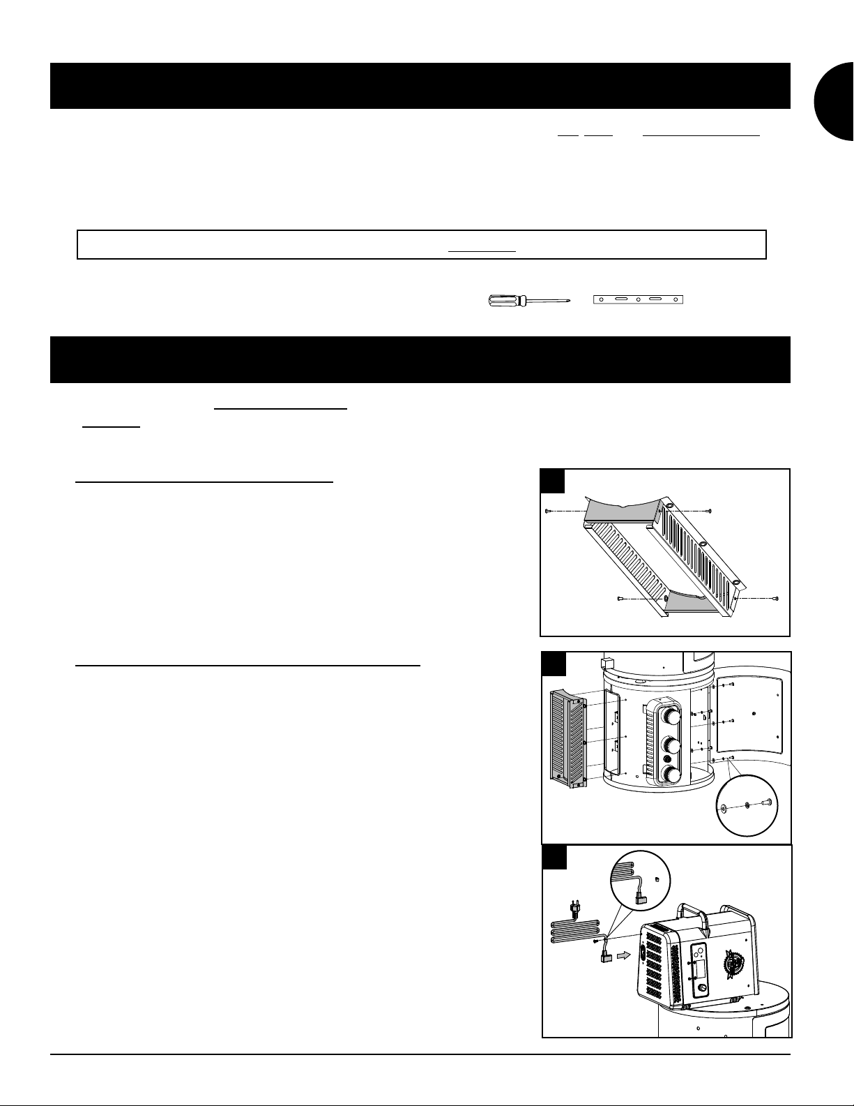
the left side, and the two slots on the Flame Broiler Main Plate will fit into the
rounded ledge above the burn pot. It will sit slightly at a downward angle.
Note illustration 17A.
IMPORTANT: If the Main Plate is resting on the base of the Barrel, it is
installed incorrectly. Poor installation may result in damage to your Main
Grill Barrel.
• Place the Flame Broiler Slider on top of the Flame Broiler Main Plate covering
the slotted openings. Ensure the raised tab is on the left and the two pins
at the bottom of the Flame Broiler Slider place into the holes of the Flame
Broiler Main Plate. To Easily adjust for direct or indirect flame when cooking.
Both Flame Broiler parts are lightly coated with oil to avoid rusting when
shipped. Note illustration 17B.
NOTE: When the flame broiler slider is open, and direct flame is used while
cooking, do not leave the grill unattended for any period of time.
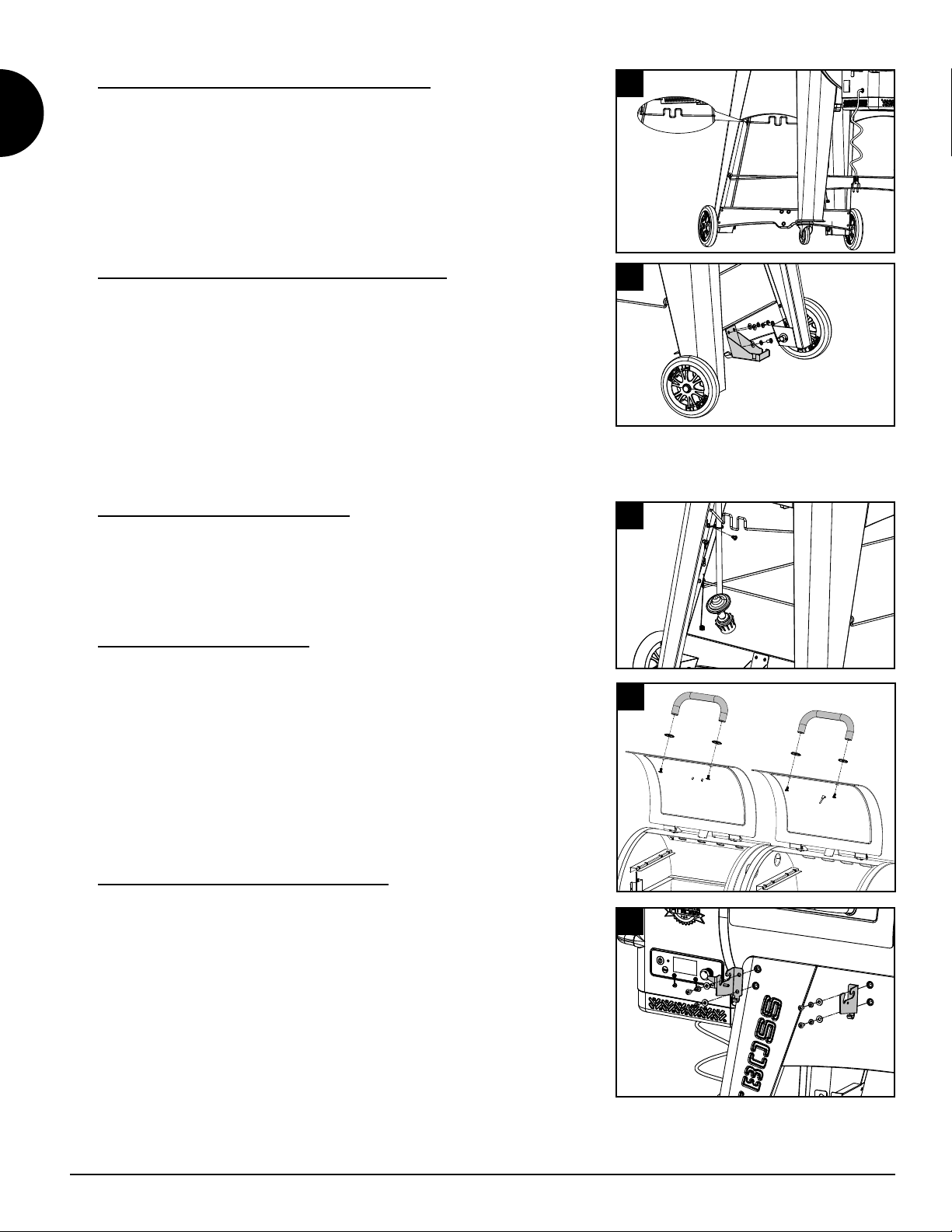
• Insert the Flame Broiler Adjusting Bar through the opening hole on the left
side of the Main Barrel. Add the Flame Broiler Adjusting Bar Handle on the
end outside the Barrel. Next, slide the notched end of the Adjusting Bar into
the locking tab on the Flame Broiler Slider, giving you adjustable access to the
Flame Broiler Slider on the Main Plate. Note illustration 17C.
• Screw in the Smoke Adjusting Bar and tighten it. Should slide from front to
back smoothly. Note illustration 17D.
• Place the three Heat Tents on the top of the burners. Place the Cooking Grids,
side-by-side, on the grid ledge inside the Main Grill. Place the Upper Cooking
Rack on the upper ledge inside the Main Grill. The Cooking Rack will lock into
place. Note illustration 17E.
NOTE: To maintain the searing and grilling performance of your cooking
grids, regular care and maintenance Is required. See Owner's Manual.
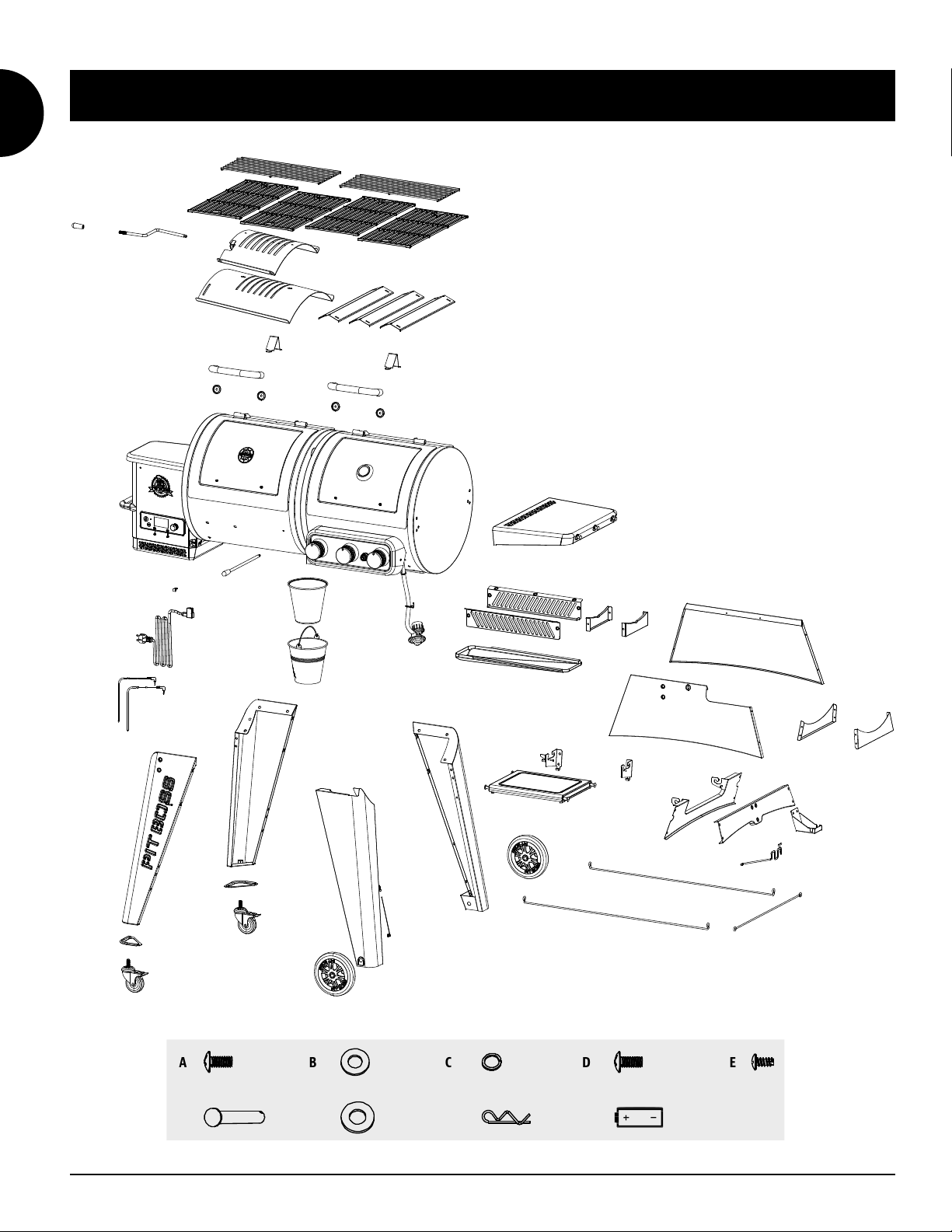
18.
Parts Required:
1 x Grease Tray
(#17)
1 x Grease Bucket Liner
(#18)
1 x Grease Bucket
(#19)
Installation:
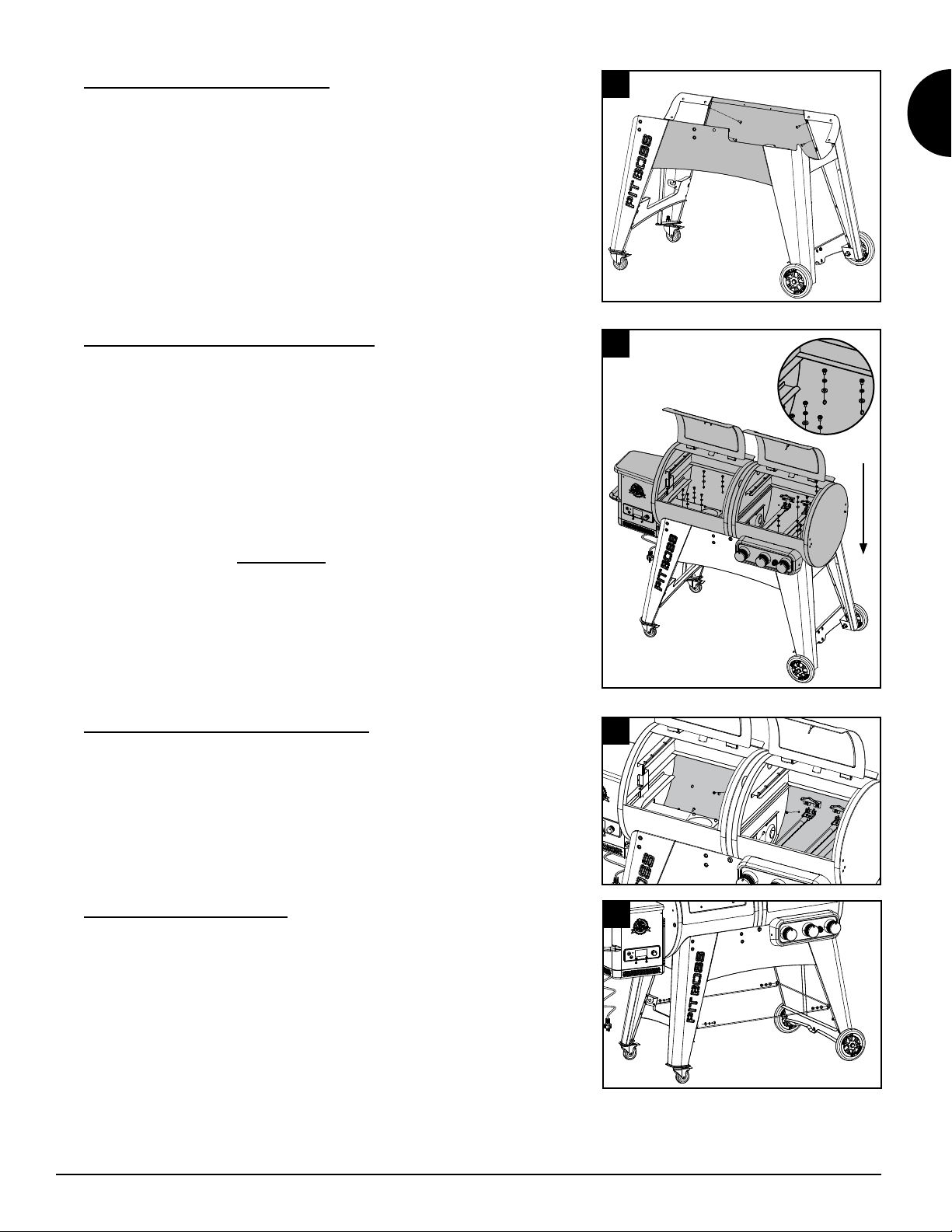
• Slide the Grease Tray into the bottom of the barrel. Note illustration 18A.
• Insert the Grease Bucket Liner inside the Grease Bucket. Place the Grease
Bucket on the spout hook on the underside of the grill. Ensure it is level to
avoid grease spills. Note illustration 18B.
PLACING THE GREASE BUCKET/TRAY
Slide the grease tray into the bottom of the barrel.
Place the grease bucket on the spout hook on the bottom of the main barrel.
Ensure it is level to avoid grease spills.
18
19
1
2
INSTALLING THE COOKING COMPONENTS
Place the cooking grids, side-by-side, on the grid ledge inside the main grill. Place the upper
cooking rack on the upper ledge inside the main grill. The cooking rack will lock into place.
IMPORTANT: To maintain optimal searing and grilling performance of your cooking grids,
regular care and maintenance is required.
17
18 18
17
5
17
1
1
22
7
INSTALLING THE COOKING COMPONENTS
Screw the smoke adjusting bar per the picture, and tighten
it. And try if it can slide from front to back smoothly.
17
13
65

11
EN
ENGLISH
19.
Parts Required:
1 x AA Battery
(#I)
Installation:
• Unscrew igniter cap from the control panel. Insert Battery into battery slot
with the positive end (+) facing outward. Screw the cap back onto the panel.
• The unit is now completely assembled.
20.
NOTE: Before plugging your Pit Boss®into any electrical outlet, ensure the
temperature dial is in the OFF position.
•
This appliance requires 220-240 volt, 50hz, 250w. It must be a 3-prong
grounded plug.
•
This appliance will work on most GFCI outlets, with a recommended size of
15 amp service. If your GFCI outlet is highly sensitive to power surges, it will
likely trip during the start-up phase of operation. During the start-up phase,
the igniter draws 200-700 watts of electricity, which can be too much power
for a GFCI outlet to handle. Each time it trips, it increases in sensitivity. If the
GFCI keeps tripping, replace the outlet or change to a non-GFCI outlet.
•
Disconnect the igniter from the main wiring harness. Use the manual
start-up procedure. A Pit Boss®unit can operate using a 12 volt, 100 watt
inverter plugged into your automobile outlet. To use the automatic
igniter, it is recommended to use a minimum of a 1000 watt inverter.
IMPORTANT: Disconnect unit from power source when not in use.
IMPORTANT: Refer to Owner's Manual for Operating Instructions
Lx1
19
20

480200429
For all questions, inquiries, or customer support, please contact
Genesis International Corporation Pty Ltd.
+61 8 9248 9822 | service@genesiscorp.com.au
WARNING This product can expose you to chemicals including carbon monoxide, which is
a combustion by-product known to cause cancer, birth defects or other reproductive harm. For more
information, go to: ...//
Other manuals for Pit Boss PB1230G
3
This manual suits for next models
1
Table of contents
Other Navigator Grill manuals

Navigator
Navigator PIT BOSS NAVIGATOR User manual

Navigator
Navigator Pit Boss PB1230G User manual

Navigator
Navigator Pit Boss PB1230G User manual

Navigator
Navigator Pit Boss PB1230G User manual

Navigator
Navigator PIT BOSS P1150G User manual

Navigator
Navigator PIT BOSS PB850G User manual

Navigator
Navigator Pit Boss PB550G User manual

Navigator
Navigator Pit Boss PB550G User manual