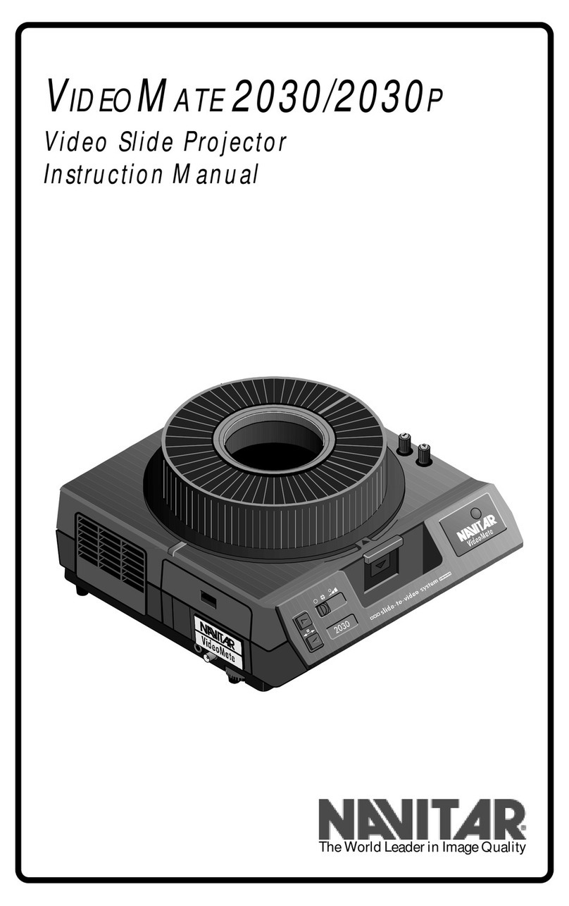
Navitar VideoMate 2300 User manual

VIDEOMATE 2300
Video Slide Projector
Instruction Manual
The World Leader in Image Quality

2Introduction to the VideoMate
4System Diagrams
6Safety Precautions
7Quick Start
8Installation & Operation
10 Slide Tray
12 Projection Lamps
13 Features and Functions
17 Troubleshooting
18 Specifications
19 Warranty
1
Table of Contents

VideoMate
Slide-to-Video
Systems
2
Introduction to the VideoMate
Description of the
VideoMate 2300
Today’s sophisticated audiences expect high quality
visual aids in the presentations they attend. Since a
picture is “worth a thousand words, ”As they say, there
is no better way to increase the effectiveness of a
presentation than to pack it full of interesting visual
images.
ANavitarVideoMateisanidealpresentationtool,
because it enables you to easily integrate 35mm
slidesintopresentationsbyconvertingthemIntovideo
imageswhichcanbeprojectedthroughavideo
projectororviewed on a TV monitor. VideoMates
producehigh resolution images with outstanding
contrastand vivid color rendition, soslides can be
shownas large projected video imageswithoutlosing
clarity or legibility. VideoMates are ideal for use in
boardrooms,auditoriums and training rooms, or for AV
rentalandvideoproduction.
TheVideoMate 2300 is based onastate-of-the-art
Kodak Ektagraphic slide projector. Integrated inside is
ahigh resolutionInterline TransferCCDcamera
featuringNavitar’sacclaimedprecisionoptics. To
increaseon-screen resolutioneven further, the
VideoMate 2300 can be used with a scan doubler.
TheVideoMate 2300 outputs Y/C (S-Video)and
composite signals. In addition, it has the ability to
genlock into a video system.
Thebuilt-inmotorizedzoomlensallowstheVideoMate
2300to zoom in on slidesfor increased magnification
or zoom out to view entire vertical slides.

VideoMate
Slide-to-Video
Introduction to the VideoMate
3
Output to Video
Equipment

4
System Diagrams
Top View
Side View

5
System Diagrams
Front View
Rear View

6
Safety Precautions
Warning
Topreventdamagetothe equipmentandoperating
personnel,please observethe followingprecautions:
Use the correct voltage source as specified on the
label.
Make sure that the voltage source contains a satisfac-
torypath to ground.
Do not operate the unit where fluids can come into
contact with the electrical components.
Maintain a six inch air space around all sides of the
equipmentto allowforproper ventilation.
Whenchangingthe bulb:
1. Disconnect the electrical supply.
2. Allow the unit to cool.
3. Use only ESJ or ESH lamps or the equivalent
(82 volt, 85 watt). Higher wattage lamps will
causesevere internal damage to thecameraand
electronics.
Thereare nouserserviceable components(otherthan
changing the lamp). Opening the unit will expose
dangerousvoltage levelsand sensitiveelectronic
components. Aqualifiedtechnicianshouldperformall
repairs.
Toprotect the unitfromdamagingcondensationand
thermalshock,certainproceduresmustbefollowed.
1. In cold weather, always put the unit in a moisture
proofcontainer orenclosure beforetransporting.
2. Eitherkeeptheunitwarmduringtransportation,or
allow sufficient time for it to warm up at the
destination. Keep the unit in the original moisture
proof package while it warms up. (The goal is to
preventwarm,moist air from striking the cold
electronic and optical components, which will
causedamaging condensation).
Never operate a cold projector to warm it up.
Safety
Precautions

7
Quick Start
Ifyouarefamiliarwith both the operation of a 35mm
slideprojectorandyourvideodisplay,youmayfollow
anabbreviatedstart-up procedure.
Before starting, review the precautions on page 6.
To “Quick Start” the VideoMate 2300, proceed as
follows:
1. Unwindthe cordunder the base of the unit and
plug it into a suitable power supply.
2. ConnectyourTVmonitortothecompositevideo
and/orY/C (S-video) output connectorsofthe
VideoMate.
3. Load the slide tray into the projector.
4. Turnthe TVmonitor on and set the VideoMate
powerswitch to HIGH.
5. Advance to the first slide.
6. Adjust the zoom lens to achieve the correct image
size.
Quick Start

8
Installation and Operation
Before starting, review the precautions on page 6.
To install the VideoMate 2300, proceed as follows:
1. Unwindthepowercordunderthebaseoftheunit
and plug it into a suitable power source.
2. Connectthe cable to your peripheralequipment
(TVmonitor,video projector, etc.). Theconnection
forcomposite video is BNC andis a 4-PIN MiniDin
forY/C(S-video).
3. Loadthe slide tray and “power-up”allequipment
4. Advance to the first slide.
5. The unit’s auto focus and auto iris functions will
adjust to produce a clear image. (To turn the auto
iris function ON/OFF, push the + and - buttons at
the same time.)
6. Using the zoom lens controls located on the unit’s
front control panel, zoom in or out to achieve the
desiredmagnification.
Navitarprovides anultrawide zoom range,allowingyou
to zoom in on a horizontal slide for increased magnifi-
cation, zoom out to see a whole vertical slide or zoom
in to fill the screen with a vertical slide.
7. Togenlock the VideoMate,a video switcher and
oneother video source are required. (SeeGenlock
section page 15). A BNC connector is needed for
the genlock input signal.
8. To shut the system down, hold the select bar down
and rotate the slide tray to the zero index position.
Set the power switch to OFF.
9. For instructions on setting up slide trays, changing
lamps, etc., refer to the appropriate sections of
this manual.
Installation

9
Installation and Operation
Due to transportation, the image position might shift
from the factory setting.
To correct this shift:
1. Removetwo plugs as shown in the figurebelow.
2. Using a Phillips screw driver, rotate screw #1 to
adjust the vertical position and screw #2 to adjust the
horizontalposition.
3. Replace the hole plugs.
CompositeVideo
Standardvideo image quality, fine forshowingpictures
of objects on a TV monitor.
Y/C (also known as S-video and S-VHS)
Improved resolution that is less grainy due to the
elimination of dot crawl. Better for presentation of text
andgraphicslides, since words are more defined.
Adjustment of
the Slide Position
on the Monitor
Understanding
Which Video
Input is Best
for You
DoNotRemoveLowerPlug
123456
123456
123456
123456
123456
123456
Adjustmentfor
HorizontalMovement
Screw#2
Adjustmentfor
VerticalMovement
Screw#1

10
Slide Tray
This system is designed to permit the use of previously
preparedpresentations withoutrequiring areorientation
of slides.
For those setting up a new tray and/or presentation:
1. Arrange the slides in the order that they should
appear in the presentation. Arrange them so that
theyareuprightandreading correctly from left to
right.
2. Rotate each slide to turn the image upside down
(do not turn the slide over). Mark a sequential
numberin the upper right cornerof each slide (this
will be extremely useful if the slides ever become
mixed). Use a felt tip marker, rather than labels
that will be loosened by the heat.
3. Make sure that the bottom metal plate on the slide
tray is indexed into the zero position (the plate will
not rotate with respect to the top tray). Remove
the top lock ring by rotating it counter clockwise.
4. Insert slide #1 into slot #1. The number written on
the upper right corner of each slide should be at
the top and facing the next higher numbered slot.
Load all slides and replace and lock the top lock
ring.
1. Centerthe tray over the postontheprojector.
2. Gently rotate the tray until the #0 slide slot is at
the index mark and the tray will drop into position.
If the tray does not drop into position, check to see
that the lower metal plate is locked in the zero
position (rotate until it locks).
Toremove thetrayfromthe projector without loosening
the slides:
1. Hold the selector bar down and rotate the tray
back to the zero index position.
2. Lift the tray at the point opposite the index mark.
Setting Up the
Slide Tray
Installing the
Slide Tray
Removing the
Slide Tray

11
Slide Tray
The tray may jam if a damaged slide is caught in the
gate. To release the tray:
1. Turnthe unit off.
2. Push the select bar down and the slide should
come up.
If the tray is still jammed:
1. Whileholding the projector post release tab
located at the center of the slide tray, grasp the
tray on the side opposite the index mark and lift.
When the tray is removed, the select bar will
release the slide.
2. Invert the slide tray and rotate the bottom metal
plate until it locks into the zero position. This will
preventtheslides from falling out from the bottom
of the slide tray.
3. Returnthetray to an upright position and remove
the lock ring. If the slide is undamaged, return it
to its proper slot. Replace the lock ring and
continue.
Slide Tray Jam

12
Projection Lamps
The VideoMate will function with either of the 85 watt,
82voltlampslistedbelow. One provides a higher color
temperature,while the otherexhibitsa much longerlife.
To prevent a severe “melt-down,” do not use 250-
300 watt, 82 volt slide projector lamps.
The entire illumination system is contained in a unit
called a lamp module. This module is a drawer type
configuration,which may beremovedfrom the projector
to change the lamp.
Unfortunately, it takes 5 to 10 minutes to change the
lamp, because it must first be allowed to cool down.
Therefore, if timing is critical, you should keep a spare
lamp module on-hand in case a lamp burns out in the
middle of a presentation. Replacing the module takes
considerably less time than changing the lamp. Spare
lamp modules can be purchased. Please call for price
andavailability.
Tochange the lamp:
1. If the unit has been running, switch the power to
FAN and wait 5 to 10 minutes for it to cool down.
2. Turn the power switch to OFF.
3. Press down on the door latch of the lamp module
and pull it slowly outward until the module clears
theprojector.
4. Unclasp the wire bail, which holds the lamp in
placeandpushfromunderneath the lamp to slide
the lamp out of the receptacle.
5. Reversethe procedure to insert thenewlamp
(make sure that the new lamp is properly seated).
6. Lock the new lamp into place with the wire bail.
Lamps
#pmaLegatloVsttaWefiL.pmeTroloC
HSE2858.rh052K0592
*JSE2858.rh04K0533
.etaMoediVhtiwdeilppuspmaldradnatS*
Replacing the
Lamp
Warning

13
Features and Functions
8-Pin Receptacle The8-pinreceptacle provides access to the circuitry of
theprojectorand allows for additional external control
andprogramming capability. Functions include forward
andreverseslidechange,sensing of the zero tray
position when the shutter is closed and electrical
grounding. 8-contactor “DIN-type” 3 and 5
contact plugs may be used. 22.5 volts of isolated
powerisavailable.
All circuits connected electrically to the projector
through this receptacle must have a rating of no
more than 30 V (rms) and must comply with
Underwriters Laboratories, Inc. low voltage, lim-
ited-energycircuit requirements.
1 and 3 (Zero Position Switch)
Connectsto an internal single-pole, single-throw,
normally open switch. Contacts are closed when the
projector slide tray is at any position other than zero.
These leads connect only to the switch terminals. Do
not exceed a switching load of 1 A at 30 V ac.
4 and 5 (Shutter Switch)
Connectsto an internal single-pole,single-throw
normally closed switch. Contacts are open when a
slide is in the projector gate and the shutter is open.
These leads connect only to the switch terminals. Do
not exceed a switching load of 1 A at 30 V ac.
Warning
8-Pin Contact
Data

14
Features and Functions
7 and 8 (Low Voltage Supply)
Foroperatingexternal equipment. The current is
supplied by a secondary winding on the main motor,
isolatedfrom theline-voltagepower,and is available
wheneverthe main projector motor is running. Supply
is 25.5 V, 500 mA (1/2 A) maximum. Contact number
8iscommon(return)for the remote-control circuit.
Contact number 7 is the “hot” lead and is fused with a
slow-blowingfuse. Replacement requires disassembly
oftheprojectorbyaqualifiedtechnician
6 and 8 (Forward Tray Cycle)
Connectstothe forward tray-advance circuitry in the
projector. These contacts are connected internally to
theremote-accessoryreceptacleandanelectrical
connection made at either receptacle will result in a
forwardcycle.
2 and 8 (Reverse Tray Cycle)
Connectstothe reverse tray-advance circuitry in the
projector. These contacts are connected internally to
theremote-accessoryreceptacleandanelectrical
connection made at either receptacle will result in a
reversecycle.
Shell (Plug Ground)
If a plug with a conducting shell is used, it is con-
nectedtotheprojectorframe (chassis) through the
special-applicationreceptacle and to earthground
throughthe projector’s cable.
The EBY remote control connector is located in the
rearofyourprojector. This5-Pin connectorcontrols
zoom,slideforward andslidereverseviaremotecontrol.
5-Pin EBY
Connector for
Remote Control

15
Features and Functions
TheVideoMate 2300 can be genlockedintoanyvideo
system. In order to utilize the genlock feature, a
secondvideosource, a video switcher box and the
appropriateinput/output cables are required. Wealso
stronglyrecommend the use of a vector scopefor the
best possible results.
Once genlock is connected, access the menu and
followthestep-by-step directions.
On-Screen Menu
→ MODE •AUTO INT
H PHASE 0
SC PHASE •0 180
SCFINE 0
When an external sync signal is input, the display
modechangesfromthefactorysetINT(internalsync)
toAUTO (external sync).
Changing AUTO Settings
To select the item you want to adjust, move the arrow
“→“ on the left side of the screen up and down by
pushingtheFUNCTIONUP,FUNCTIONDOWN
buttons. Once you choose an item, you can change
the setting by pushing the DATA UP, DATA DOWN
buttons.
Adjusting the Horizontal Phase
1. Set the arrow “→“ to H PHASE by pushing the
FUNCTIONUP,FUNCTIONDOWNbuttons.
2. Adjust the horizontal phase by pushing the DATA
UP,DATADOWNbuttons.Thevalues range from
-99 to 99, DATA UP will increase the setting
towards99 and DATA DOWN will decrease it
towards-99.
Coarse Adjustment of the Sub Carrier Phase
1. Set the arrow “→“ to SC 0/180 by pushing the
FUNCTIONUP,FUNCTIONDOWNbuttons.
2. Select either 0 or 180 by pushing the DATA UP,
DATADOWN buttons.
Genlock
Genlock
Adjustment

16
Features and Functions
Y/C Genlock and
Composite Video
Genlock
Genlock Diagram
Adjusting the Sub Carrier Phase
1. Set the arrow “→“ to SC PHASE by pushing the
FUNCTIONUP,FUNCTIONDOWNbuttons.
2. Adjust the sub carrier phase by pushing the DATA
UP,DATADOWN buttons. The valuesrangefrom
-99 to 99, DATA UP will increase the setting
towards99 and DATADOWNwill decrease it
towards-99.
Theon-screenresolutionoftheY/C(S-video)imageis
lessgrainyandappearssharperthanthecomposite
videoimage. Untilnow,videomanufacturersonlyallowed
thecompositevideosignaltobegenlockedwithavideo
switcher system. The technology in the VideoMate
2300,however,nowallowsthehigherqualityY/Cimage
tobegenlockedtoaY/Cvideoswitcher,therebyimprov-
ingtheon-screenpicturequality. Forstandardapplica-
tions you can genlock the composite video signal.

Troubleshooting
17
MOTPMYSYDEMER/ESUAC
onsierehT .neercs-noegami lacirtceleehtfollakcehC"?pu-derewop"tnempiuqeehtfollasI .sehctiwsrewoptnempiuqednasteltuo
dabsrotcennocroselbacehterA
".noitidnocnothgil"arofetagmlifehtnikooL?nwolbpmalehtsI
ehtnwodhsuP?noitisopdesolcehtnikcutsrettuhsetagehtsI .tiesaelerdnarabtceles
.tratserotyrtnehtdnaetunimenotiaw,FFOothctiwsrewopehtnruT
elbanuerauoY ehtrevocerot aretfaegami noitpurretnifeirb .rewopfo
yamnotinuehtgninrutfokcohslamrehtehT?nwolbpmaLehtsI .wolbotpmalehtdesuacevah
ehtnonwodhsuP?noitisopdesolcanikculsrettuhsetagehtsI .tiesaelerotrabtceles
ootsiegamiehT .thgilootrokrad .deriuqersa)I(siriehtteS?etauqedalevelnoitanimulliehtsI
?yltcerrocdetsujdarotinomehtsI
tonsiegamiehT .prahs ?ylreporpdetsujdasucofehtsI
.deriuqersa)I(siriehtteS?hgihootlevelnoitanimulliehtsI
?yltcerrocdetsujdarotinomehtsI
ebdluohsyehT?selbacfoedargtcerrocehtgnisuuoyerA .MHO57,edarg"oedivdleihsdednuorg"
seodegamiehT .ezilibatston .kcolnegroftnemtsujdaunemehtkcehC
kcolnegehT etarepotonseod .ylreporp
detcennocrehctiwsoedivehtfotuodnanigniogselbacehterA ?ylreporp
?tcerrocstnemtsujdaesahpesraocdnaenifehterA

18
Camera
eciveDpu-kciP)3(DCCrefsnartenilretni"3/1
tnuoClexiP3x)V(494x)H(867CSTN
metsySlangiSdradnatsCSTN
noituloseRlatnoziroHsenilVT064
ytivitisneSerutarepmetrolocK0023,)xuL7(8.1F
kcolneGdnaamorhcesraocdnaenif,seY tnemtsujdaesahp-H
oitaRN/SdradnatsBd84
rebmuNledoM10431-1
noitpmusnoCrewoPspma7.1,sttaw191
rewoPzH06,stlov021
pmaLrotcejorPJSEEGttaw58,tlov28
sneLdezirotoMX21
slortnoCsucoF/sirIdezirotoM
launaM/slortnoC,tuo/nimooz,esrever/drawrof,ffo/nO siri&sucof
noitarepOetomeRerusolctcatnocybdellortnocetomeR otsrotcennocnip-5dradnatsgnisu esrever/drawrofdnamoozlortnoc
srotcennoCaremaC,kcolneg&oediVetisopmoC-CNB )oediV-S(C/Y-niDiniMnip-4
snoisnemiDmm013/.ni11.11htgneL mm823/.ni39.21htdiW mm911/.ni96.4thgieH .gk28.6/.sbl51thgieW
selbaCoediV )lanoitpo( elbacoediV-S,toof21,31111-8ledoM etisopmoCtoof21,78711-1ledoM elbacoediV
Projector
Specifications
Design and specifications are subject to change
withoutnotice.

Warranty
Thisproductiswarrantedtobefreefromdefectsin
materialand workmanship foraperiod of fiveyears
fromthe date of invoice to the original purchaser.
Ifduringthewarrantyperiodtheproductisfoundtobe
defective,itwillberepaired or replaced at the facilities
ofNavitar.However,Navitarreservestherighttorefund
the purchase price if the replacement or repair is not
commercially practical or timely. Parts not manufac-
turedbyNavitar carry only the warranty of their manu-
facturer.Lamps and fuses carry no warranty.
Thiswarranty does not cover damagecausedin
transit; damage caused by misuse, neglect or care-
lessness;or damage resulting from either improper
servicingor modification by someone otherthan
Navitar.Further,this warrantydoesnot cover any
routinemaintenancework that is reasonably expected
tobeperformed by the purchaser.
No responsibility is assumed for unsatisfactory
operatingperformanceduetoenvironmentalconditions
such as humidity, dust, corrosive chemicals, deposi-
tionofoilorother foreign matter,spillageorother
conditionsbeyond the control ofNavitar.
Forservice, repair or returnproceduresunder this
warranty,contactyourdistributor, your local Navitar
fieldofficer orNavitardirect at(716)359-4000 or(800)
828-6778intheUnitedStates.
Except as stated herein, Navitar makes no other
warranties,expressedor implied by law, whether of
merchantability, fitness for a particular purpose or
otherwise.Further,Navitar shall not, under any circum-
stances,beliable for incidental, consequential or other
damages.
Thiswarrantyappliesonlytothoseoriginalpurchasers
(non-dealers)returning theproductwarranty card within
30 days of purchase date. For purchasers who do not
return the warranty card within 30 days, or for items
sold to dealers for their own use or rental use, our
standard90 day parts and 1year labor warranty will
apply.
5 Years Parts/
5 Years Labor
19
Other Navitar Projector manuals

Navitar
Navitar VideoMate 5000 User manual

Navitar
Navitar FX User manual

Navitar
Navitar ColorPro User manual

Navitar
Navitar VideoMate 2250 User manual

Navitar
Navitar VideoMate 5000 User manual

Navitar
Navitar VideoMate 7500XY User manual

Navitar
Navitar FX User manual

Navitar
Navitar 560 User manual

Navitar
Navitar 10K User manual

Navitar
Navitar VideoMate 6100 User manual